Pepperl+Fuchs VBA-4E4E-G11-ZAJ-F Operating instructions
- Type
- Operating instructions

Merkmale
www.pepperl-fuchs.com
Pepperl+Fuchs GmbH
68301 Mannheim · Germany
Tel. +49 621 776-4411
Fax +49 621 776-27-4411
E-mail: fa-info@de.pepperl-fuchs.com
Worldwide Headquarters
Pepperl+Fuchs GmbH · Mannheim · Germany
E-mail: fa-info@de.pepperl-fuchs.com
USA Headquarters
Pepperl+Fuchs Inc. · Twinsburg · USA
E-mail: fa-info@us.pepperl-fuchs.com
Asia Pacific Headquarters
Pepperl+Fuchs Pte Ltd · Singapore
E-mail: [email protected]
Company Registration No. 199003130E
AS-Interface-Sensormodul
AS-Interface sensor module
Part-No: 251408 EDM: 45-4760
Date: 2015-10-08 DIN A3 -> DIN A7
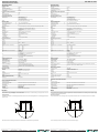
Abmessungen Dimensions
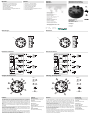
Elektrischer Anschluss Electrical connection
Adressen
Addresses
Features
Bestellbezeichnung
Model Number
VBA-4E4E-G11-ZAJ-F
G11 Modul
2 x 4 Eingänge
G11 module
2 x 4 inputs
• Eingänge für 2-, 3- und 4-Draht-Sensoren
• Versorgung der Sensoren aus AS-Interface
• Funktionsanzeige für Bus und Eingänge
• Schutzart IP68 / IP69K
• Kommunikationsüberwachung
• Durchdringungstechnik mit vergoldeten Kontakt-Pins
•AS-Interface POWER24
• Inputs for 2-, 3-, and 4-wire sensors
• Supply of sensors from AS-Interface
• Function display for bus and inputs
• Degree of protection IP68 / IP69K
• Communication monitoring
• Cable piercing method with gold plated contact pins
•AS-Interface POWER24
Zubehör
VBP-HH1-V3.0-KIT
AS-Interface Handheld mit Zubehör
VAZ-V1-B3
Blindstopfen für M12-Buchsen
VBP-HH1-V3.0
AS-Interface Handheld
VAZ-PK-1,5M-V1-G
Adapterkabel Modul/Handprogrammier-
gerät
VAZ-FK-S-BK-SEAL
AS-Interface Flachkabeldichtung
35
Ø 85
35
Ø 85
Accessories
VBP-HH1-V3.0-KIT
AS-Interface Handheld with accessory
VAZ-V1-B3
Blind plug for M12 sockets
VBP-HH1-V3.0
AS-Interface Handheld
VAZ-PK-1,5M-V1-G
Adapter cable module/hand-held pro-
gramming device
VAZ-FK-S-BK-SEAL
AS-Interface flat cable seal
für 3-Draht-
Sensoren
(frei) (frei)
(frei) (frei)
4-Draht-
Sensoren
für 3-Draht-
Sensoren
für 3-Draht-
Sensoren
4-Draht-
Sensoren
für 3-Draht-
Sensoren
Sensor -
Sensor +
Sensor -
Sensor +
Sensor -
Sensor +
Sensor -
Sensor +
AS-i
FAULT
1
2
4
3
1
2
4
3
AS-Interface -
AS-Interface +
ADDR
IN
1
IN1.1
IN+
IN-
IN1.1
IN1.2
IN1.3
IN+
IN-
IN1.3
IN1.4
IN1.2
IN+
IN-
IN1.2
IN1.4
IN+
IN-
IN1.4
AS-i
FAULT
1
2
4
3
1
2
4
3
IN2.1
IN+
IN-
IN2.1
IN2.2
IN2.3
IN+
IN-
IN2.3
IN2.4
IN2.2
IN+
IN-
IN2.2
IN2.4
IN+
IN-
IN2.4
ADDR
Slave 1
Slave 2
for 3-wire
sensors
(nc) (nc)
(nc) (nc)
4-wire
sensors
for 3-wire
sensors
for 3-wire
sensors
4-wire
sensors
for 3-wire
sensors
Sensor -
Sensor +
Sensor -
Sensor +
Sensor -
Sensor +
Sensor -
Sensor +
AS-i
FAULT
1
2
4
3
1
2
4
3
AS-Interface -
AS-Interface +
ADDR
IN
1
IN1.1
IN+
IN-
IN1.1
IN1.2
IN1.3
IN+
IN-
IN1.3
IN1.4
IN1.2
IN+
IN-
IN1.2
IN1.4
IN+
IN-
IN1.4
AS-i
FAULT
1
2
4
3
1
2
4
3
IN2.1
IN+
IN-
IN2.1
IN2.2
IN2.3
IN+
IN-
IN2.3
IN2.4
IN2.2
IN+
IN-
IN2.2
IN2.4
IN+
IN-
IN2.4
ADDR
Slave 1
Slave 2
Funktion
Das VBA-4E4E-G11-ZAJ ist ein AS-Interface-Anschaltmodul mit 2 x 4 Eingängen.
Das Anschaltmodul ist mit 2 getrennten AS-Interface Chips bestückt und belegt 2 A/B-
Adressen. Im Auslieferungzustand belegen beide Slave-Adressen die Adresse 0. Der
zweite Slave ist bis zur Adressierung des ersten Slave deaktiviert. Dadurch wird eine
Doppeladressierung vermieden. An die plusschaltenden Elektronikeingänge können
sowohl 2-und 3-Drahtsensoren als auch mechanische Kontakte angeschlossen wer-
den.
Das Gehäuse mit einer Zentralschraube ermöglicht eine schnelle Montage auf der
Grundplatte.
Die Verbindung zu den Sensoren erfolgt über M12x1-Steckanschlüsse auf der Geräte-
oberseite. Das AS-Interface Flachkabel wird mittels Durchdringungstechnik an der
Unterseite des Moduls angeschlossen.
Die Eingänge und die angeschlossenen Sensoren werden aus der internen Versor-
gung des Moduls (aus AS-Interface) gespeist.
Der aktuelle Schaltzustand jedes Eingangs wird über jeweils eine LED IN angezeigt.
Die LEDs AS-i/FAULT zeigen den Status des AS-Interface an (Normalbetrieb, Kommu-
nikationsfehler, Peripheriefehler, Adresse 0). Das Anschaltmodul besitzt eine Doppel-
adressierbuchse und ist kompatibel zu AS-Interface POWER24.
Function
The VBA-4E4E-G12-ZAJ is an AS-Interface switch-on module with 8 inputs. The
switch-on module is equipped with 2 separate AS-Interface chips and uses 2 A/B
addresses. In the delivered state, both slave addresses use the address 0. The
second slave is deactivated until the first slave is addressed. Duplicate addressing is
avoided in this way. 2 and 3-wire sensors can also be connected as mechanical
contacts to the PNP electronic inputs.
The housing with a central screw enables fast mounting on the base plate.
The connection to the sensors is via an M12x1 plug-in connection on the top side of
the device. The AS-Interface flat cable is connected via the insulation piercing techno-
logy on the underside of the module.
The inputs and the connected sensors are powered by the internal supply of the
module (from the AS-Interface).
The current switching state of each input is indicated via an IN LED. The AS-i/FAULT
LEDs indicate the status of the AS-Interface (normal operation, communication error,
peripheral fault, address 0). The switch-on module has a double addressing jack and
is compatible with AS-Interface POWER24.
Anzeigen / Bedienelemente
Eingang 1 bis 4
Eingang 1 bis 4
Statusanzeigen
43
12
5
9
1 4
...
5 8
...
9
1
2
3
4
5
6
7
8
Slave 1
Slave 2
Indicating / Operating means
Input 1 to 4
Input 1 to 4
Status indication
43
12
5
9
1 4
...
5 8
...
9
1
2
3
4
5
6
7
8
Slave 1
Slave 2

VBA-4E4E-G11-ZAJ-FAS-Interface-Sensormodul
AS-Interface sensor module
Germany: +49 621 776 4411Pepperl+Fuchs Group
Refer to “General Notes Relating to Pepperl+Fuchs Product Information”.
USA: +1 330 486 0001 Singapore: +65 6779 9091
Deutschland: +49 621 776 1111
Beachten Sie „Allgemeine Hinweise zu Pepperl+Fuchs-Produktinformationen“.
Pepperl+Fuchs-Gruppe USA: +1 330 486 0001 Singapur: +65 6779 9091
fa-info@de.pepperl-fuchs.com
Montagehinweise
Schrauben Sie das Gerät mit zwei Befestigungsschrauben M5 auf einer planen Montagefläche fest. Die Befestigungsschrauben
liegen nicht bei.
Schrauben Sie auf nicht benötigte Anschlüsse einen Blindstopfen, um die Schutzart zu gewährleisten.
Technische Daten
Allgemeine Daten
Slave-Typ A/B-Slave
AS-Interface-Spezifikation V3.0
Erforderliche Master-Spezifikation ≥ V2.1
UL File Number E223772
Kenndaten funktionale Sicherheit
MTTFd 120 a
Gebrauchsdauer (TM) 20 a
Diagnosedeckungsgrad (DC) 0 %
Anzeigen/Bedienelemente
LED AS-i/FAULT 2 Dual-LED grün/rot
grün: AS-Interface-Spannung
rot: Kommunikationsfehler
gelb/rot blinkend: Adresse 0
grün/rot blinkend: Überlast Sensorversorgung
LED IN Schaltzustand (Eingang); 8 LED gelb
Elektrische Daten
Bemessungsbetriebsspannung Ue18,0 ... 31,6 V aus AS-Interface
Bemessungsbetriebsstrom Ie≤ 80 mA (ohne Sensoren) / max. 280 mA
Schutzklasse III
Überspannungsschutz Ue: Überspannungskategorie III, sicher getrennte Spannungsversorgungen (PELV)
Eingang
Anzahl/Typ 2x 4 Eingänge für 2- oder 3-Drahtsensoren (PNP), DC
alternativ 2x 2 Eingänge für 4-Drahtsensoren (PNP), DC
Versorgung aus AS-Interface
Spannung 12 ... 31 V
Strombelastbarkeit ≤ 200 mA, überlast- und kurzschlussfest
Eingangsstrom ≤ 9 mA (intern begrenzt)
Schaltpunkt gemäß DIN EN 61131-2 (Typ 2)
0 (unbedämpft) ≤ 3 mA
1 (bedämpft) ≥ 5 mA
Signalverzögerung < 1 ms (Eingang/AS-Interface)
Programmierhinweise
Profil S-0.A.2
IO-Code 0
ID-Code A
ID1-Code Slave 1 Slave 2
12
ID2-Code 2
Datenbit (Funktion über AS-Interface) Eingang Slave 1Eingang Slave 2
D0 IN1.1 IN2.1
D1 IN1.2 IN2.2
D2 IN1.3 IN2.3
D3 IN1.4 IN2.4
Parameterbit (programmierbar über AS-i) Funktion
P0 nicht verwendet
P1 Eingangsfilter
P1 = 0 Eingangsfilter ein, Impulsunterdrückung ≤2ms
P1 = 1 Eingangsfilter aus (Grundeinstellung)
P2 Synchronmodus
P2 = 0 Synchronmodus ein
P2 = 1 Synchronmodus aus (Grundeinstellung)
P3 nicht verwendet
Umgebungsbedingungen
Umgebungstemperatur -25 ... 70 °C (-13 ... 158 °F)
Lagertemperatur -25 ... 85 °C (-13 ... 185 °F)
Relative Luftfeuchtigkeit 85 % , nicht kondensierend
Klimatische Bedingungen Einsatz nur in Innenräumen
Einsatzhöhe ≤ 2000 m über NN
Schock- und Stoßfestigkeit 30 g, 6 ms in 6 Raumrichtungen 3 Schocks
10 g, 16 ms in 6 Raumrichtungen 1000 Schocks
Vibrationsfestigkeit 0,35 mm 10 ... 57 Hz , 5 g 57 ... 2000 Hz, 10 Zyklen
Verschmutzungsgrad 3
Mechanische Daten
Schutzart IP68 / IP69K
Anschluss AS-Interface: AS-Interface Flachkabel
Eingänge: M12-Rundsteckverbinder
Material
Ge h ä u se PB T P C
Befestigungsschraube Edelstahl 1.4305 / AISI 303 (V2A)
Masse 200 g
Anzugsmoment Gehäuseschrauben 1,8 Nm
Anzugsmoment Kabelverschraubung 0,4 Nm
Befestigung Montageplatte
Normen- und Richtlinienkonformität
Richtlinienkonformität
EMV-Richtlinie 2004/108/EG EN 61000-6-2:2005, EN 61000-6-4:2007, EN 50295:1999
Normenkonformität
Störfestigkeit EN 61000-6-2:2005, EN 61326-1:2006, EN 50295:1999
Störaussendung EN 61000-6-4:2007
Eingang EN 61131-2:2007
Schutzart EN 60529:2000
Feldbusstandard EN 50295:1999, IEC 62026-2:2006
Hinweise
Verbinden Sie bei Ein- und Ausgängen, die über das Modul aus AS-Interface oder über Hilfsenergie versorgt werden, keinen der
Signal- oder Versorgungsanschlüsse mit externen Potentialen.
5.5
50
60
Ø 85.8
Mounting instructions
Screw the device onto a level mounting surface using two M5 attachment screws. The attachement screws are not included.
Screw a blind plug onto spare connections to ensure the protection category.
Technical data
General specifications
Slave type A/B slave
AS-Interface specification V3.0
Required master specification ≥ V2.1
UL File Number E223772
Functional safety related parameters
MTTFd 120 a
Mission Time (TM) 20 a
Diagnostic Coverage (DC) 0 %
Indicators/operating means
LED AS-i/FAULT 2 Dual LEDs green/red
green: AS-Interface voltage
red: Communication error
yellow/red flashing: Address 0
green/red flashing: Sensor supply overload
LED IN switching state (input); 8 LED yellow
Electrical specifications
Rated operating voltage Ue18,0 ... 31.6 V from AS-Interface
Rated operating current Ie≤ 80 mA (without sensors) / max. 280 mA
Protection class III
Surge protection Ue: Over voltage category III, safe isolated power supplies (PELV)
Input
Number/Type 2x 4 inputs for 2- or 3-wire sensors (PNP), DC
alternative 2x 2 inputs for 4-wire sensors (PNP), DC
Supply from AS-Interface
Voltage 12 ... 31 V
Current loading capacity ≤ 200 mA, overload and short-circuit protected
Input current ≤ 9 mA (limited internally)
Switching point according to DIN EN 61131-2 (Type 2)
0 (unattenuated) ≤ 3 mA
1 (attenuated) ≥ 5 mA
Signal delay < 1 ms (input/AS-Interface)
Programming instructions
Profile S-0.A.2
IO code 0
ID code A
ID1 code Slave 1 Slave 2
12
ID2 code 2
Data bits (function via AS-Interface) Input slave 1input slave 2
D0 IN1.1 IN2.1
D1 IN1.2 IN2.2
D2 IN1.3 IN2.3
D3 IN1.4 IN2.4
Parameter bits (programmable via AS-i) function
P0 not used
P1 Input filter
P1 = 0 input filter on, pulse suppression ≤2ms
P1 = 1 input filter off (basic setting)
P2 Synchronous mode
P2 = 0 synchronous mode on
P2 = 1 synchronous mode off (basic setting)
P3 not used
Ambient conditions
Ambient temperature -25 ... 70 °C (-13 ... 158 °F)
Storage temperature -25 ... 85 °C (-13 ... 185 °F)
Relative humidity 85 % , noncondensing
Climatic conditions For indoor use only
Altitude ≤ 2000 m above MSL
Shock and impact resistance 30 g, 6 ms in 6 spatial directions, 3 shocks 10 g, 16 ms in 6 spatial directions, 1000 shocks
Vibration resistance 0.35 mm 10 ... 57 Hz , 5 g 57 ... 2000 Hz, 10 cycles
Pollution Degree 3
Mechanical specifications
Degree of protection IP68 / IP69K
Connection AS-Interface: AS-Interface flat cable
Inputs: M12 round connector
Material
Housing PBT PC
Mounting screw Stainless steel 1.4305 / AISI 303
Mass 200 g
Tightening torque, housing screws 1.8 Nm
Tightening torque, cable gland 0.4 Nm
Mounting Mounting base
Compliance with standards and directi-
ves
Directive conformity
EMC Directive 2004/108/EC EN 61000-6-2:2005, EN 61000-6-4:2007, EN 50295:1999
Standard conformity
Noise immunity EN 61000-6-2:2005, EN 61326-1:2006, EN 50295:1999
Emitted interference EN 61000-6-4:2007
Input EN 61131-2:2007
Degree of protection EN 60529:2000
Fieldbus standard EN 50295:1999, IEC 62026-2:2006
Notes
Do not connect inputs and outputs, which are supplied via the module from AS-interface or via auxiliary power, with power supply
and signal circuits with external potentials.
5.5
50
60
Ø 85.8
-
 1
1
-
 2
2


Pepperl+Fuchs VBA-4E4E-G11-ZAJ-F Operating instructions
- Type
- Operating instructions
Ask a question and I''ll find the answer in the document
Finding information in a document is now easier with AI
in other languages
Related papers
-
Pepperl+Fuchs VBA-4E-G11-ZAJ-F Operating instructions
-
-
-
-
-
-
-
-
-