Page is loading ...

Your pump has been carefully packaged at the
factory to prevent damage during shipping.
However, occasional damage may occur due
to rough handling. Carefully inspect your
pump for damages that could cause failures.
Report any damage to your carrier or your
point of purchase.
INSTALLATION
INSTRUCTIONS
2190 Dagenais Blvd.West
Laval (Quebec)
Canada
H7L 5X9
Tel. : 514.337.4415
Fax : 514.337.4029
see us at www.burcam.com
© 2022 BURCAM Printed in Canada 510154
Please read these instructions carefully. Failure to comply to instructions and designed operation of this
system, may void the warranty.
READ THIS DOCUMENT IN TOTALITY PRIOR TO STARTING THE INSTALLATION.
PRIMING PROCESS
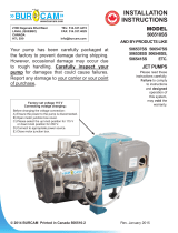
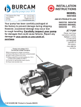
Follow all these step by step instructions to install your pump. Use teon tape on all threads. (1) Fill
the suction line with water and connect it to the suction inlet. (2) Remove the priming plug and ll
the pump body with water. (3) Screw the plug to the priming inlet. (4) Connect the power cable to a
115V, 60Hz electrical outlet. The pump should deliver water to the plumbing line within 30 seconds.
If not, unplug the pump and repeat the process at step 2.
2-3
1’’ Discharge connection
1 1/4’’ Suction connection
4
1
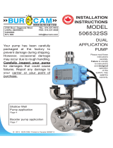
MODEL
506732P
TANKLESS
CONVERTIBLE
JET PUMP

This ne pump that you have just purchased is designed from the latest in material
and workmanship. Before installation and operation, we recommend the following
procedures :
Check with your local electrical and plumbing codes to ensure you comply with the
regulations. These codes have been designed with your safety in mind. Be sure
you comply with them.
We recommend that the pump be used on a separate circuit lead from the home
electrical distribution panel , and which is protected with a fuse or a circuit breaker.
The motor must be securely plugged into a proper ‘GFCI’ electrical outlet. Consult
a licensed electrician for all wiring.
The ground terminal on the three prong plugs should never be removed. They are
supplied and designed for your protection.
Never make adjustments to any electrical appliance or product with the power
connected. Do not only unscrew the fuse or trip the breaker, remove the power
plug from the receptacle.
A
B
C
D
SAFETY INSTRUCTIONS :
1. Inspect the pump for any obvious condition that necessitates cleaning, correction, adjustment or repair.
2. Clear the surroundings of any paper, leaves or other debris.
3. Ensure that the pump is secure for proper operation.
4. Ensure that there is adequate clearance from any combustible materials or structure. Stored
materials must be kept away from the pump. Shelves or cabinet structures must not be in close
proximity to the pump.
5. Ensure that the motor is securely plugged into a proper ‘GFCI’ electrical outlet.
6. Test the ‘GFCI’ outlet by pressing its test switch. This should prove that the outlet is energized and
will trip o to protect against a ground fault. Be sure to reset the ‘GFCI’ by pressing its reset switch.
7. Observe that the plumbing can carry the water safely into the residence.
MONTHLY MANDATORY CHECK-UP :
2
Material required for drilled well application (indoor use only)
Shallow well pump installation
Desired length of polyethylene 1 1/4’’ pipe, 100 PSI, CSA
or UL approved, to link up from pumping level to pump.
1 1 1/4'' male adaptor barb to MNPT.
1 1 1/4'' foot valve 750757 or 750753P.
1 well seal, as per well casing diameter (750929 6’’ x 1’’).
1 1 1/4’’ well seal elbow (750861).
1 1 1/4’’ male adaptor (750866 or 750872).
8 1 1/4’’ stainless steel clamps (750886).
Teon tape.
Deep well pump installation
Desired length of polyethylene 1 1/4’’
and 1’’ pipe, 100 PSI, CSA or UL approved,
to link up from pumping level to pump.
1 1 1/4'' nipple.
1 1 1/4'' foot valve 750757 or 750753P.
1 well seal, as per well casing diameter
(750926 6’’ x 1 1/4’’ x 1’’).
1 1’’ well seal elbow (750860).
1 1 1/4’’ well seal elbow (750861).
1 1’’ male adaptors (750865 or 750871).
1 1 1/4’’ male adaptor (750872 or 750866).
8 1’’ stainless steel clamps (750885).
8 1 1/4’’ stainless steel clamps (750886).
Teon tape.
Tools
Screwdrivers, hacksaw to cut pipe, knife to assist in pipe cutting, round le to smooth pipe ends, pipe
wrench, adjustable wrench to tighten ttings, propane torch and welding material.

APPLICATION :
This pump is designed for shallow well
installation for water level up to 25 feet
with injector screwed on pump body; or
for deep well installation for water level up
to 80 feet, with 2 pipes and injector down
in the well.
CAPACITY :
FEATURES :
High performance impeller.
Industrial motor totally enclosed, fan-cooled.
Full-time connected run capacitor, to
eliminate starting wear vs regular motor.
Thermal and overload protection.
Built for continuous use.
3/4 HP, 115VAC, 60Hz, 9A
(18A when the pump start).
We recommend that you install your pump in a clean and dry location
where there is adequate room for servicing at a later date. Protection
from freezing temparatures and good ventilation should be considered
as well, to provide the pump an environment for long life. Locating the
pump as close as possible to the water source will reduce friction losses
encountered in the suction pipe.
Friction losses in the suction pipe must be taken into consideration when
the horizontal oset is greater than 50 feet. The suction pipes should be
increased from 1’’ to 1 1/4’’ and 1 1/4’’ to 1 1/2’’. This will reduce friction
losses and allow the pump to give maximum performance.
A new well should be checked to determine that it is free from sand. Sand
will damage the seal and the impeller. Have your well driller clean the well
before your installation.
Never run the pump dry. Damage to the seal may occur. Fill pump body
and suction pipe with water before turning on the power.
THE RUN OF THE HORIZONTAL PIPE FROM THE TOP OF YOUR WELL
INTO THE HOUSE, WHERE YOUR PUMP WILL BE LOCATED, MUST BE
INSTALLED IN A TRENCH, BELOW THE FROST LEVEL OF YOUR AREA.
Friction loss in pipe not included.
INSTALLATION STEPS
STEP 1
3
SHALLOW WELL
25’ 300 US GPH
5’ 800 US GPH
DEEP WELL
70’ 200 US GPH
30’ 675 US GPH
VERY IMPORTANT
Please be advised that the Fluomac Electronic unit is a state of the art product and will
give you years of trouble free service. However, if the unit cycles ‘‘ON and OFF’’, this
means there is a leakage in your plumbing. For example : A toilet leak, the leakage must
be repaired to maintain the system pressure.
Furthermore, if you are pumpling water from a sand point or if you have indication that your
well may contain sand, a sand lter must be installed in the suction of the pump.
Sand will damage the unit, due to its abrasive nature and will void warranty. For more
information, we are enclosing a brochure on our Sand Filter model # 750896, which is
available from any Burke Retailers or Wholesalers. In the meanwhile, if you have any
questions concerning your pump, please contact us on our toll free number
1-800-361-1820 before returning the pump to the point of purchase.
The above conditions are not on warranties. The warranty covers manufacturing defects only.

SELECTION OF APPLICATION
Prior to continue to step 2, select your application.
Shallow well venturi
Motor
Pump body
1 1/4’’ venturi adaptor
1’’ venturi adaptor
Ejector body
Deep well venturi
Shallow well
application
Your pump is already set for being used in shallow well application.
Connect your suction pipe to the 1 1/4’’ suction inlet and the house
plumbing distribution pipe to the 1’’ discharge outlet. At all time, the
ejector draining plug must be aligned down.
Maximum vertical
distance from
pumping level
of water and the
pump cannot
exceed 25 feet.
4
Identication of suction inlet and discharge outlet.
1 1/4’’
suction
inlet
1’’ discharge
outlet

5
Then unscrew the shallow well venturi from the ejector body.
Screw the deep well venturi to the same opening.
Deep well
application
Maximum vertical
distance from
pumping level
of water and the
pump cannot
exceed 80 feet.
Unscrew the large coupling collar to separate the ejector from the pump body.
Then screw the 1 1/4’’ venturi adaptor onto the venturi.
Finally, screw the 1’’ venturi adaptor to the other opening of the ejector body.

Cut the desired lenght of poly pipe to run from the top of the well to the
pumping level. Smooth the pipe cuttings with your round le. (Check that no
cut-out parts are left inside of pipe. This may block pump injector or impeller).
Tape male adaptor threads with teon tape and thread adaptor into the
foot valve. Slide 2 stainless steel clamps over one end of pipe and use
torch to soften pipe. Insert the male adaptor and foot valve into this pipe
end. Tighten clamps with screwdriver. For security against leaks, we
suggest to install 2 stainless steel clamps on each adaptor.
Insert the well seal elbow thru the opening of the seal.
Slide 2 stainless steel clamps over the free end of the previously cut pipe
and soften pipe with your torch. Attach pipe to the well seal elbow
(end protruding at bottom of well seal). Tighten clamps with screwdriver
when cool.
Install the well seal and piping assembly into your well casing. Tight down
the seal bolts using your adjustable wrench.
To facilitate servicing at a later date, you may use a pitless adaptor and a
sealed well cap instead of an elbow and a well seal as described in steps
3 and 4.
Install your pump in the house, on a sound foundation, as close as possible
to the basement wall. Thread an adaptor into inlet using teon tape. Do
not over tighten.
Cut the desired length of pipe from pump location to the well seal and
connect both ends using the previous way, with stainless steel clamps and
torch. Before connecting your pipe to the pump, ll the suction line with water.
Do not ll in your trench to the house until you have checked for any
leaks in your connections or trouble in your water system.
Sand or well points are limited to areas where water bearing sand or
gravel lies below the surface, and where there are no boulders or rocks to
interfere with the driving into the ground of the point.
The amount of water any ‘‘one’’ well point will supply is usally rather
limited. Sometimes, it is necessary to use more than one point to increase
the supply of water entering to the pump’s suction.
THE IMPORTANT INSTALLATION STEP IN USING WELL POINTS IS THAT
A CHECK VALVE MUST BE USED IN THE SUCTION PIPE LEADING TO THE
SUCTION INLET, AS CLOSE TO THE PUMP AS POSSIBLE, TO KEEP LINE AND
PUMP WELL PRIMED.
STEP 2
STEP 3
STEP 4
STEP 5
STEP 6
STEP 7
for sand
or well
point
SHALLOW WELL APPLICATION
SEE DIAGRAM ON PAGE 8
6

As per the description on page 5, remove the ejector body from the pump body.
Then remove the shallow well venturi and replace it by the deep well venturi.
Then screw the 1 1/4’’ venturi adaptor on the deep well venturi and the 1’’
venturi adaptor on the other opening.
With teon tape on threads, install a 1 1/4’’ nipple into the 1 1/4’’ foot valve,
then screw this assembly into the 1 1/4’’ bottom opening of the ejector.
Cut the desired lenght of 1’’ and 1 1/4’’ poly pipes to run from the top of the well
to the pumping level. Smooth the pipe cuttings with your round le. (Check
that no cut-out parts are left inside of pipe. This may block pump injector or
impeller). Slide 2 stainless steel clamps over one end of each pipe and use
torch to soften pipe. Fix the 1” and 1 1/4” pipes respectively on the 1” adaptor
and 1 1/4” venturi adaptor. Tighten clamps with screwdriver when cool.
For security against leaks, we suggest that you install 2 stainless
steel clamps on each adaptor.
Insert both well seal elbows through their opening of the seal. Slide 2
stainless steel clamps over the free ends of the previously cut pipes and
soften pipes with your torch. Attach pipes to the well seal elbows (ends
protruding at bottom of well seal). Tighten clamps with screwdriver when cool.
Install the well seal and the ejector piping assembly into your well casing.
Tighten down the well seal bolts using your adjustable wrench.
Install your pump in the house, on a sound foundation, as close as possible
to the basement wall. Locate the openings in the front of the pump body.
Thread respectively 1” and 1 1/4” adaptors into corresponding openings
using teon tape. Do not over tighten.
Cut the desired length of pipes from pump location to the well seal and connect
both ends using the previous way, with stainless steel clamps and torch.
Do not ll in your trench to the house until you have checked for any
leaks in your connections or trouble in your water system.
STEP 2
STEP 3
STEP 4
STEP 5
STEP 6
STEP 7
STEP 8
SEE DIAGRAM ON PAGE 9
DEEP WELL APPLICATION
7
To facilitate servicing at a later date, you may use a pitless adaptor and
a sealed well cap instead of an elbow and a well seal as described in
steps 3 and 4.

SHALLOW WELL APPLICATION
8
Well point optional installation
STEP 6
Cut poly pipe and connect both ends.
STEP 4
Install well seal
and piping into well casing.
STEP 2
Cut poly pipe
and install the
check valve.
Check valve,
close to pump.
STEP 3
Insert well seal elbow
through the seal and
attach to pipe.
STEP 7
You may install one or more sand points to
increase the supply of water.
STEP 5
Install your pump and
thread an adaptor into inlet.

DEEP WELL APPLICATION
9
STEP 3
Install 1 1/4" nipple into 1 1/4"
foot valve, then screw into the
ejector.
STEP 6
Install well seal and piping
into well casing.
STEP 8
Cut 1" and 1 1/4’’ poly pipes
and connect both ends.
STEP 2
Set the ejector as per the page 5
description.
STEP 4
Cut 1" and 1 1/4’’ poly pipes.
STEP 5
Insert well seal elbows thru
the seal and attach to pipe.
STEP 7
Install your pump and thread adaptors
into their respective opening.

Connect your discharge line, using a ball
valve, as illustrated (Photo 1).
Fill the suction line with water and connect
it to suction inlet (Photo 1).
Remove the plug of the priming pipe and
ll the pump body with water (Photo 1).
Screw the plug to the priming pipe using
teon tape (Photo 2).
Connect the pump. The pump should
delivered water to the plumbing line within 30
seconds. If not, unplug the pump and repeat
from step 10. In accordance with the lenght
of your suction line, you may have to repeat
these steps a few times.
NOTE : After installation, if the pump is cycling ‘‘ON-OFF’’ and/or comes
on when you are not visibly using water, the pump is not defective. It
means you have a leak on the discharge side of the pump. The leak
must be localised and needs to be repaired. If you need assistance to
determine same, please call 1-800.361.1820. The pump is warrantied
by the manufacturer and you must call us to dertermine procedures.
The pump cannot be returned to the point of purchase without our
prior consent.
STEP 1
STEP 2
STEP 3
STEP 4
STEP 5
PLEASE, FOLLOW THESE STEPS TO EASILY PRIME YOUR PUMP
PRIMING INSTRUCTIONS
10
STEP 3
STEP 1
STEP 2
STEP 4
STEP 5
PHOTO 2
PHOTO 1

Repair parts may be ordered your authorized point of sale of from
BURCAM PUMPS
REF ITEM DESCRIPTION
1 510121 Pump body screw
2 510122 Flat washer
3 510123 Pump body
4 510124 Rubber ring
5 510125 Diuser
6 510126 Shaft sleeve
7 510127 Impeller
8 510128 Mechanical seal
9 510129 O ring
10 510130 Seal plate
11 510131 Motor
12 510132 Capacitor
13 510133 Connection box
14 750957S Pressure switch kit
15 750748 Tube
16 510134 Elbow tting
17 750769 Pressure gauge
REF ITEM DESCRIPTION
18 510135 Drain plug
20 510137 Primming plug
21 510138 O Ring
22 510139 Shallow well venturi#63
23 510140 Nozzle#17
24 510141 Screw
25 510142 Inner ejector body
26 510143 Gasket
27 510144 Plug
28 510145 Ejector body
29 510146 Shallow well ejector collar
33 510150 Deep well venturi#2
34 510151 Outlet venturi tube#32
35 510152 Inlet tube connector
42 506375 SS Priming tube
43 506377 Priming plug & washer
44 506376 Discharge tting
45 600600GP Fluomac
REPAIR PARTS
11

Switch is o position
Blown fuse
Tripped breaker
Dirty pressure switch
Defective pressure switch
Defective motor
Pump not primed
Leaky suction line
Foot valve plugged
Injector nozzle clogged
Water level below foot valve
Suction lift to great
Improper voltage
Water level below foot valve
Injector nozzle clogged
Excessive friction in pipe
Improper voltage
Leaky discharge line
Motor not up to normal speed
Improper setting of pressure switch
Ejector nozzle clogged
Pressure tank waterlogged
Leaky foot valve
Leaky suction line
Foot valve do not close properly
Pressure switch out of adjustment
Leaky discharge line (toilet etc.)
Leaky suction line
Gaz in water
Airlogged tank (galvanized)
NEVER MAKE ADJUSTMENTS TO ANY ELECTRICAL APPLIANCE OR PRODUCT WITH THE POWER CONNECTED.
DON’T JUST UNSCREW THE FUSE OR TRIP THE BREAKER, REMOVE THE POWER FROM THE RECEPTACLE.
TROUBLE PROBABLE CAUSE ACTION
TO THE END CONSUMER
If you have any problems with the product, before advising the store, where you’ve
purchased the pump, please contact us at 514 337-4415, and ask for our sales
department, and they will be pleased to help you with any questions you might have, concerning
your installation.
Motor does not run.
Motor runs but no water is
delivered.
Pump does not deliver to
full capacity.
Pump does not shut o.
Pump start stop too often.
Air spurts from faucets.
Turn switch to on position
Replace
Reset
Clean
Replace
Replace
Prime with clean water
Check pipe and pipe connections
Clean
Clean
Check foot valve level
Water level lower than lift capacity
Check voltage
Check foot valve level
Clean
Too small or dirty pipe
Check voltage
Check all pipes for leak
Check power cable and voltage
Reset or replace
Clean
Drain tank and restart
Replace
Check pipe and pipe connections
Clean or replace
Adjust ON/OFF setting
Check all pipes for leak
Check pipe and pipe connections
Check and consult factory
Replace air volume control
12
TROUBLE SHOOTING GUIDE CHECKLIST
Unit may be defective.
Lost of prime due to a low water level condition.
Water pipe obstructed from water supply to
pump.
Power cut-o by thermal protector.
Pump cannot reach proper
minimum operational pressure.
Lost of pressure due to leak
in the piping.
The water column to the highest tap exceed
50 feet.
Power supply is on, no
light are lit.
Power supply is on, pump
on light is o, failure light
is on.
Power supply is on, pump
on light is on, failure light is
o, and pump short cycles
ON and OFF.
Power supply is on, pump
on light is on, failure light is
o, tap is open and no ow.
Pump is o.
Test electrical therminals with voltmeter. If there is no
power, replace the unit.
Wait for water level resume and press reset buttom.
Clean obstruction and press reset button.
Wait 10 minutes and press reset button.
Clogged pump nozzle and/or venturi, clean
and press reset button.
Make sure all taps are closed and all toilet
valves are functionning.If leak not found,
install a back valve after the Fluomac. If cycling stops,
leak is at the supply line. If cycling occurs, leak is at
suction line. Foot valve may be defective or clogged.
Replace.
Pessure of water of water column is higher the cut-in
pressure (26 PSI). Re-install the unit at a higher level.
FLUOMAC TROUBLE SHOOTING GUIDE CHECKLIST
/