Page is loading ...


2
SAFETY INSTRUCTIONS
1. Read these instructions.
2. Keep these instructions.
3. Heed all warnings.
4. Follow all instructions.
5. Do not use this apparatus near water.
6. Clean only with a dry cloth.
7. Do not block any ventilation openings. Install in accordance
with the manufacturer’s instructions.
8. Do not install near any heat sources such as radiators, heat
registers, stoves, or other apparatus (including amplifi ers) that
produce heat.
9. Do not defeat the safety purpose of the polarized or
grounding-type plug. A polarized plug has two blades with
one wider than the other. A grounding-type plug has two
blades and a third grounding prong. The wide blade or
the third prong are provided for your safety. If the provided
plug does not fi t into your outlet, consult an electrician for
replacement of the obsolete outlet.
10. Protect the power cord from being walked on or pinched
particularly at plugs, convenience receptacles, and the point
where they exit from the apparatus.
11. Only use attachments/accessories specifi ed by the
manufacturer.
12. Use only with a cart, stand, tripod, bracket, or table specifi ed
by the manufacturer, or sold with the apparatus. When a
cart is used, use caution when moving the cart/apparatus
combination to avoid injury from tip-over.
13. Unplug this apparatus during lightning storms or when unused
for long periods of time.
14. Refer all servicing to qualifi ed service personnel. Servicing
is required when the apparatus has been damaged in any
way, such as when the power-supply cord or plug has been
damaged, liquid has been spilled or objects have fallen into
the apparatus, the apparatus has been exposed to rain or
moisture, does not operate normally, or has been dropped.
15. This apparatus shall not be exposed to dripping or splashing,
and no object fi lled with liquids, such as vases, shall be
placed on the apparatus.
16. This apparatus has been designed with Class-I construction
and must be connected to a mains socket outlet with a
protective earthing connection (the third grounding prong).
17. The MAINS plug or an appliance coupler is used as the
disconnect device, so the disconnect device shall remain
readily operable.
18. This apparatus has been equipped with a double-pole AC
mains power switch. This switch is located on the rear panel
and should remain readily accessible to the user.
19. NOTE: This equipment has been tested and found to comply
with the limits for a Class B digital device, pursuant to part
15 of the FCC Rules. These limits are designed to provide
reasonable protection against harmful interference in a
residential installation. This equipment generates, uses, and
can radiate radio frequency energy and, if not installed and
used in accordance with the instructions, may cause harmful
interference to radio communications. However, there is no
guarantee that interference will not occur in a particular
installation. If this equipment does cause harmful interference
to radio or television reception, which can be determined by
turning the equipment off and on, the user is encouraged to
try to correct the interference by one or more of the following
measures:
• Reorient or relocate the receiving antenna.
• Increase the separation between the equipment and
the receiver.
• Connect the equipment into an outlet on a circuit
different from that to which the receiver is connected.
• Consult the dealer or an experienced radio/TV
technician for help.
CAUTION: Changes or modifi cations to this device not
expressly approved by LOUD Technologies Inc. could void the
user's authority to operate the equipment under FCC rules.
20.
This apparatus does not exceed the Class A/Class B
(whichever is applicable) limits for radio noise emissions
from digital apparatus as set out in the radio interference
regulations of the Canadian Department of Communications.
ATTENTION —Le présent appareil numérique n’émet pas de bruits
radioélectriques dépassant las limites applicables aux appareils numériques
de class A/de class B (selon le cas) prescrites dans le règlement sur le
brouillage radioélectrique édicté par les ministere des communications du
Canada.
21.
Exposure to extremely high noise levels may cause permanent
hearing loss. Individuals vary considerably in susceptibility to
noise-induced hearing loss, but nearly everyone will lose some
hearing if exposed to suffi ciently intense noise for a period of
time. The U.S. Government’s Occupational Safety and Health
Administration (OSHA) has specifi ed the permissible noise level
exposures shown in the following chart.
According to OSHA, any exposure in excess of these
permissible limits could result in some hearing loss. To ensure
against potentially dangerous exposure to high sound
pressure levels, it is recommended that all persons exposed to
equipment capable of producing high sound pressure levels
use hearing protectors while the equipment is in operation.
Ear plugs or protectors in the ear canals or over the ears must
be worn when operating the equipment in order to prevent
permanent hearing loss if exposure is in excess of the limits set
forth here:
WARNING — To reduce the risk of fi re
or electric shock, do not expose this
appliance to rain or moisture.
Duration Per Day Sound Level dBA, Typical
In Hours Slow Response Example
8 90 Packed garage concert
6 92
4 95 VW Bus Peace Train
3 97
2 100 Cranked psychedelic tunes
1.5 102
1 105 High speed chase on C.H.I.P.s
0.5 110
0.25 or less 115
Loudest parts at a Heavy Metal concert
PORTABLE CART WARNING
Carts and stands - The
Component should be used
only with a cart or stand
that is recommended by
the manufacturer.
A Component and cart
combination should be
moved with care. Quick
stops, excessive force, and
uneven surfaces may cause
the Component and cart
combination to overturn.
CAUTION AVIS
RISK OF ELECTRIC SHOCK
DO NOT OPEN
RISQUE DE CHOC ELECTRIQUE
NE PAS OUVRIR
CAUTION: TO REDUCE THE RISK OF ELECTRIC SHOCK
DO NOT REMOVE COVER (OR BACK)
NO USER-SERVICEABLE PARTS INSIDE
REFER SERVICING TO QUALIFIED PERSONNEL
ATTENTION: POUR EVITER LES RISQUES DE CHOC
ELECTRIQUE, NE PAS ENLEVER LE COUVERCLE. AUCUN
ENTRETIEN DE PIECES INTERIEURES PAR L'USAGER. CONFIER
L'ENTRETIEN AU PERSONNEL QUALIFIE.
AVIS: POUR EVITER LES RISQUES D'INCENDIE OU
D'ELECTROCUTION, N'EXPOSEZ PAS CET ARTICLE
A LA PLUIE OU A L'HUMIDITE
The lightning flash with arrowhead symbol within an equilateral
triangle is intended to alert the user to the presence of uninsulated
“dangerous voltage” within the product’s enclosure that may be
of sufficient magnitude to constitute a risk of electric shock to persons.
Le symbole éclair avec point de flèche à l'intérieur d'un triangle
équilatéral est utilisé pour alerter l'utilisateur de la présence à
l'intérieur du coffret de “voltage dangereux” non isolé d'ampleur
suffisante pour constituer un risque d'éléctrocution.
The exclamation point within an equilateral triangle is intended to
alert the user of the presence of important operating and maintenance
(servicing) instructions in the literature accompanying the appliance.
Le point d'exclamation à l'intérieur d'un triangle équilatéral est
employé pour alerter les utilisateurs de la présence d'instructions
importantes pour le fonctionnement et l'entretien (service) dans le
livret d'instruction accom
p
a
g
nant l'a
pp
areil.

Part No. SW0696 Rev. B 08/08
©2006-2008 LOUD Technologies Inc. All Rights Reserved.
3
What me, read a manual?
Your new TAPCO
®
powered mixer is designed to bring you great joy, as you share your
wonderful skills and love of music with the world. Before you begin, make sure you read the
safety instructions on page 2 and getting started on page 4. You can read the rest of the
manual whenever you get a free moment in your busy schedule.
It is important to keep your receipt in a safe place, and not a bad idea to write your
product information here for future reference (i.e., insurance claims, tech support, return
authorization, etc.).
Don’t forget to visit our website at www.tapcoworld.com
for more information about this and other TAPCO products.
Contents
Safety Instructions .....................................2
Getting Started ..........................................4
Introduction ...............................................5
Hookup Diagrams .....................................6
Rear Panel Features ................................10
1. Power Connection ..................10
2. Power Switch ............................10
3. Speaker-level Outputs .............11
4. Ventilation .................................11
Front Panel Features ...............................12
Connector Section .............................12
5. Mic Inputs..................................12
6. Mono Line Inputs ......................13
7. Stereo Line Inputs .....................13
8. RCA Inputs ................................13
9. Monitor Send ...........................13
10. Tape Outputs ...........................13
11. Main Outputs ...........................13
12. Power Amp Mode Switch .......14
13. Power Amp Inputs ..................14
Channel Controls ................................15
14. High EQ .....................................16
15. Mid EQ .......................................16
16. Low EQ ......................................16
17. Aux Send Mon ..........................17
18. Aux Send FX ..............................17
19. Overload (OL) Led ...................17
20. Channel Level ..........................17
21. Gain Switch ..............................17
Master Controls ...................................18
22. Power Led .................................18
23. Phantom Switch and Led .......18
24. Break Switch and Led .............18
25. Main Master Graphic EQ ........18
26. Main Mix Meters .......................19
27. FX To Main .................................19
28. Main Master Level ....................19
29. Monitor Graphic EQ ................19
30. Monitor Meter ...........................19
31. FX To Monitor ............................19
32. Monitor Master Level ...............20
33. Series 69 EQ ..............................20
Internal Effects .....................................20
34. Preset Selector .........................20
35. OL Led .......................................20
Table of Internal Effects .................21
Appendix A: Service Information ..........22
Appendix B: Connections ......................23
Appendix C: Technical Information ......24
TAPCO Limited Warranty ........................27
Product Serial #:
Purchased at:
Date of purchase:

4
Getting Started
We realize that you must be
really keen to try out your new
powered mixer, but please
read the safety instructions on
page 2, and this page fi rst.
SETUP
1. Place the powered mixer in a position
where it is easy to reach the controls.
All the controls and input connections
are located on the front panel so you
can make quick adjustments and
connections on stage.
2. Make sure there is at least 6 inches of
airspace behind the powered mixer for
ventilation. Use the powered mixer in a
nice clean and dry environment.
CONNECTIONS
1. Be sure the rear-panel power switch is
off before making any connections.
2. Push the linecord securely into the
IEC connector on the rear panel, and
plug the other end into a 3-prong AC
outlet that is properly confi gured for the
voltage of your powered mixer.
3. Plug a balanced microphone into one
of the mic XLR (3-pin) connectors on
the front panel. Or you can connect a
line-level source (keyboard, or guitar
preamp) to a line input jack using a TRS
1/4" plug.
4. You will need a DI box to connect
guitars/instruments to the powered
mixer.
5. Plug your passive speakers (4 ohms or
greater) into the speaker output jacks
on the rear panel. If you plug two
speakers into a side, each speaker must
be 8 ohms or greater to maintain a 4-
ohm minimum load on the amplifi er.
Use at least 18 gauge speaker cable
with 1/4" TS plugs or Speakon
®
plugs. For
now, set the power amp mode switch
to stereo mains.
Don’t use guitar cords for speaker
cables! They’re not designed to
handle speaker-level signals and
could overheat.
READY, STEADY, GO!
1. Turn down all the channel level, mon,
and FX controls.
2. Set all the EQ controls to the center,
including the graphic EQ sliders.
3. Turn down the main master level and
monitor master level controls, and turn
on the powered mixer.
4. For condenser mics, push in the
phantom power switch. If you are using
both condenser and dynamic mics,
don’t worry. Phantom power will not
hurt most dynamic mics. Check the
micro phone’s user manual if you’re not
sure.
5. For each channel 1-6, press the gain
switch in (low gain) if you are using a
line-level source. Press it out (high gain)
if you are using a microphone or other
low-level source.
6. Play something into an input at real-
world levels, and turn up the channel
level to U (unity).
7. In normal playing, the channel's OL
LED should only light occasionally. If
it stays on for a large portion of your
performance, check that the gain
switch is set correctly.
8. Slowly turn up the main master level
control until you hear the signal in your
speakers.
9. Repeat steps 5 to 7 for the remaining
channels.
10. If needed, apply some EQ wisely.
11. Adjust the levels to get the best mix.
Keep the level controls fully down on
unused channels.
Other Notes
• Only connect the powered mixer's
speaker-level outputs to passive
loudspeakers.
• When shutting down, turn off any
external amplifi ers or powered
loudspeakers fi rst. When powering
up, turn on any external amplifi ers or
powered loudspeakers last.
• Save the shipping box!

5
• Two internal power amplifi ers, each
rated at 500 watts peak into 4 ohms
• Two selectable amplifi er modes
(stereo mains, mono-main/monitor)
• 10 channels.
• XLR microphone inputs on all
channels
• TRS Line-level inputs (mono on Ch. 1
to 6, stereo on Ch. 7 and 8)
• RCA stereo inputs on Ch. 9 and 10
• 3-band EQ on each channel
• Separate Aux mon and FX controls
on each channel
• Monitor send line-level output
• Main mix stereo line-level output
• RCA stereo tape outputs for
recording the main mix
• Amplifi er line-level inputs allow the
connection of external mixers if more
channels are needed
• Phantom power can be applied to
all mic inputs
• 16 built-in TAPCO-designed effects
from an internal digital processor
Introduction
Thank you for choosing a TAPCO MIX10fxP powered mixer. We grin with happiness over all
the fun you will have.
The TAPCO product line hails back to the days of TAPCO Corporation, Greg Mackie’s
fi rst company. TAPCO revolutionized the audio industry back in 1969 with the very fi rst 6-
channel mixer specifi cally designed for keyboards and rock ‘n’ roll.
In essence, TAPCO redefi ned the price/performance ratio, and made high-quality
professional audio equipment accessible to virtually anyone. Today, TAPCO is reborn
with the same ideals, and is backed by the world-class engineering and manufacturing
horsepower of LOUD Technologies.
This versatile powered mixer can be used in a variety of applications, and we hope you
have a wonderful time using it. With its 10 splendid channels, two powerful amplifi ers, and
lightweight power supply, all fi tted into a box smaller than a medium-sized pirate’s treasure
chest, it makes the ideal companion for those who want to spread their musical love.
Here’s a quick look at all the features packed into the powered mixer:
• 7-band stereo graphic EQ on the
main outputs
• 7-band graphic EQ on the monitor
output
• Stereo meters on main mix, and
mono meter on monitor mix
• Overload LED on each channel
• Break switch mutes channels 1-8
• Speakon and 1/4" power amp
speaker-level outputs
• Series 69 EQ switch for enhanced
clarity and low-frequency response
with TAPCO Series 69 passive
speakers
• Top-mounted handle for easy and
joyous transport from gig to gig
• Can be placed in wedge position for
easy access to controls during gig
• Ultra-lightweight and portable
• This powered mixer with all its knobs,
buttons and lights, will make you
almost completely irresistible
• People will love the way you fi x your
hair, fi nd you charming, and laugh at
all your jokes

Microphones
Keyboard
6915 Passive Speakers
(plays stereo main mix)
TAPCO J-2500
Power Amplifier
TAPCO Thump-15A Powered Speakers
used as Stage Monitors
Recorder
Amp Mode
switch set to
Stereo Main
Acoustic Guitar
and Mic
Electric
Guitar
DB-1A
DI Box
6918s Passive Subwoofers
Po le M o u n t
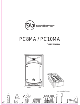
This diagram shows microphones attached to channels 1 to 4, an electric guitar connected via a TAPCO DB-1A
DI box to channel 5, an acoustic guitar and mic to channel 6, and a keyboard attached to channel 7's stereo
inputs. A portable recorder is attached to the stereo tape outputs to record the performance.
TAPCO Thump TH15A powered speakers are connected to the monitor send, and are set up as stage monitors.
The aux mon controls of each channel allow you to create a stage monitor mix that is independent of the main
mix. Use the monitor graphic EQ to adjust the stage monitor EQ as desired.
TAPCO 6915 passive speakers are connected to the speaker-level power output of the powered mixer, and they
play the main stereo mix to your audience. The Series 69 EQ switch is engaged to enhance the performance
with these Series 69 speakers. TAPCO 6918s passive subwoofers are powered by a TAPCO J-2500 power amplifi er,
connected to the main line outputs to reinforce the low end in your system.
6
Hookup Diagrams
Club System

Microphones
Keyboard 1
CD/DVD
Player
6912 Passive Speakers
6912 Passive Speakers
TAPCO J-2500
Power Amplifier
Stage Monitors
Thump TH-15A
Powered Speakers
in Overflow Room
or Cry Room
Keyboard 2
Amp Mode
switch set to
Stereo Main
Acoustic Guitar
and Mic
Electric
Guitar
DB-1A
DI Box
TAPCO Link.USB
Laptop
USB
This diagram shows microphones attached to channels 1 to 4, an electric guitar connected via a TAPCO DB-1A
DI box to channel 5, a guitar mic to channel 6, keyboards attached to channel 7 and 8 stereo inputs, and a
CD/DVD player connected to channel 9's RCA inputs. A TAPCO Link.USB Digital Audio Interface is attached to
the stereo tape outputs to record the performance via USB onto a laptop.
A TAPCO J-2500 power amplifi er is connected to the line-level monitor send output, and powers four passive
stage monitors, two per side.
TAPCO 6912 passive speakers are connected to the speaker-level power output of the powered mixer, and
they play the main mix to your audience. There are two per side, connected in parallel, (minimum impedance
of 4 ohms per side).
TAPCO Thump TH15A powered speakers are connected to the main line-level outputs, and are set up to play
the main mix to an overfl ow room. Alternatively, you could run Thump TH18s powered subwoofers to reinforce
the low end in your main room.
7
House of Worship

Drum Kit Mics
Vocal
Microphones
6912 Passive Speakers
(plays mono main mix)
Amp Mode
switch set to
Main/Mon
Bass
Guitar
Electric
Guitar
DI Box
Guitar
Processor
Thump TH-18s Powered Subwoofers
Pole Mount
TAPCO Link.USB
Digital Audio Interface
Laptop
USB
CD Player
iPod Dock
Floor Monitors
(play monitor mix)
This diagram shows drum kit microphones connected to channels 1 to 4, a guitar connected via a TAPCO
DI box to channel 5, a guitar processor connected to the line input of channel 6, vocal mics connected to
channels 7 and 8, a CD player connected to channel 9's stereo RCA inputs, and an iPod dock connected to
channel 10's stereo RCA inputs. A TAPCO Link.USB Digital Audio Interface is attached to the stereo tape outputs
to record the performance via USB to a laptop.
The amp mode switch is set to main/mon. Passive stage monitors are connected to the speaker-level Ch.B
output, and play the monitor mix for your performers. TAPCO 6912 passive speakers are connected to the
speaker-level Ch.A output, and they play the main mono mix to your audience. TAPCO Thump TH18s powered
subwoofers are connected to the main line-level outputs, to reinforce the low end in your system.
8
Band Practice

Drum Kit Mics
6912 Passive Speakers
(play stereo main mix)
TAPCO J-2500
Power Amplifier
Stage Monitors
Amp Mode
switch set to
Stereo Main
Acoustic Guitar
and Mic
Electric
Guitar
Bass
Guitar
TAPCO J-1400
Power Amplifier
Recorder
6925 Passive Speakers
(play stereo main mix)
Vocal
Microphones
DI Box
Gtr
Proc.
This diagram shows drum kit microphones connected to channels 1 to 4, a guitar connected via a TAPCO DI
box to channel 5, a guitar processor connected to the line input of channel 6, an acoustic guitar with guitar
mic connected to channel 7, and vocal mics connected to channels 8, 9 and 10.
A TAPCO J-1400 power amplifi er is connected to the line-level monitor send output, and powers two passive
stage monitors. Monitor EQ can be adjusted with the monitor graphic EQ, and internal FX added.
A portable recorder is attached to the stereo tape RCA outputs to record the performance.
The amp mode switch is set to stereo mains. TAPCO 6912 passive speakers are connected to the speaker-level
outputs, and they play the main stereo mix to your audience. A TAPCO J-2500 power amplifi er is connected to
the main line-level outputs, and supplies speaker-level power to 6925 passive speakers to reinforce the volume
for outdoor events.
9
Outdoor gig

10
Rear Panel Features
2. POWER SWITCH
Press the top of this rocker switch to turn
on the mixer. The front panel power LED (22)
will glow with happiness, or at least it will if
you have the mixer plugged into a suitable
live AC mains supply.
Press the bottom of this switch to turn off
the mixer, whenever you feel that this would
be a safe thing to do. Half-way through a
guitar solo by RagnaKX, self-proclaimed
Rock-Master-General from the Metal Planet
Tarquin-5 might not be such a good time.
As a general guide, you should turn on
your mixer fi rst, before any external power
amplifi ers or powered speakers, and turn it
off last. This will reduce the possibility of any
turn-on, or turn-off thumps in your speakers.
1. POWER CONNECTION
This jack accepts the supplied 3-prong IEC
AC power cord.
Before you plug the AC power
cord into the powered mixer, make
sure that the voltage of your unit
is the same voltage as your local
AC mains supply. Use only the power cord
supplied. Also, disconnecting the plug’s
ground pin is dangerous. Please don’t do it.
1
2
3
4

11
3. SPEAKER-LEVEL OUTPUTS
These output connections provide
speaker-level output power from the
internal power amplifi ers to your passive
speakers. The peak power output is 500
watts per channel into 4 ohms.
Only passive loudspeakers should
be connected to these speaker-
level outputs.
The outputs can be selected with the
amp mode switch (12) to be either the
stereo main mix, or the mono main mix on
output A, and the monitor mix on output B.
Two common types of connector are
provided for your convenience: Speakons
®
and 1/4" TS.
Mono Speakon Connection
• Speakon outputs are wired Pin 1+
positive (hot) and Pin 1– negative
(cold).
1/4" TS Connection
• 1/4" TS outputs are wired Tip positive,
and Sleeve negative.
These two types of outputs are wired in
parallel, and it is possible to use both types
at once.
The minimum impedance that
the powered mixer can handle
is 4 ohms per channel, and we
recommend that you do not go
below this. If you are using both output styles
per channel, make sure each loudspeaker is
8 ohms impedance or greater.
COLD
HOT
1+
1+
1–
1–
2–
2+
SLEEVE
TIP
TIP
SLEEVE
TIP
SLEEVE
4. VENTILATION
Do not obstruct these ventilation slots, or
the internal amplifi ers may overheat and
shut down.
Allow at least six inches of free space
behind the powered mixer when in use.

14
15
16
17
18
20
21
19
5
6
7 8 8
6 6 6 6 6
5 5 5 5 5 5 5 5 5
9
10
11
12
22
23
24
25
26
29
30
33
34
27
28
31
13
32
7
35
12
Front Panel Features
Microphone-level signals are passed
through the mixer's splendid microphone
preamplifi ers to become line-level signals.
Because more gain is required to boost the
microphone level signals, make sure the
gain switch (21) is in the out (high) position
when you are using microphones. The mic
inputs for channels 7 to 10 have no gain
switch; the mic gain is fi xed at the low gain
setting of channels 1 to 6.
The microphone signals appear equally in
the left and right of the main mix.
PHANTOM POWER
Most modern professional condenser
mics require phantom power, which lets the
mixer send low-current DC voltage to the
mic’s electronics through the same wires
that carry audio. (Semi-pro condenser mics
often have batteries to accomplish the
same thing.) “Phantom” owes its name to
an ability to be “unseen” by dynamic mics
(Shure SM57/SM58, for instance), which
don’t need external power and aren’t
affected by it anyway.
Connector Section
This is where you plug things in, such as:
microphones, line-level instruments, guitar
preamps and effects, recorders, external
amplifi ers, powered monitors, powered
subwoofers etc. (The speaker-level outputs
from the internal power amplifi ers are on
the rear panel.) Check out the hookup
diagrams for some connection ideas. See
Appendix B (page 23) for further details
and some rather lovely drawings of the
connectors you can use with your powered
mixer.
5. MIC INPUTS
We use phantom-powered, balanced
microphone inputs just like the big tour
mega-consoles, for exactly the same
reason: This kind of circuit is excellent at
rejecting hum and noise. You can plug in
almost any kind of mic that has a standard
XLR-type male mic connector.
Professional ribbon, dynamic, and
condenser mics all sound excellent through
these inputs. The mic inputs will handle
any kind of mic level you can toss at them,
without overloading.

13
The mixer's phantom power is globally
controlled by the phantom (23) switch on
the front panel. (Phantom power for all mics
is turned on and off together.)
Never plug single-ended
(unbalanced) micro phones, or
ribbon mics into the mic input jacks
if phantom power is on. Do not
plug instrument outputs into the mic XLR
input jacks with phantom power on, unless
you know for certain it is safe to do so.
6. MONO LINE INPUTS (CH. 1 to 6)
These 1/4" jacks share circuitry (but not
phantom power) with the mic preamps,
and can be driven by balanced or
unbalanced sources.
To connect balanced lines to these inputs,
use a 1⁄4" Tip-Ring-Sleeve (TRS) plug.
To connect unbalanced lines to these
inputs, use a 1⁄4" mono (TS) phone plug or
instrument cable.
The mono line-level signals appear
equally in the left and right of the main mix.
7. STEREO LINE INPUTS (CH. 7 and 8)
In addition to a mic input, channels 7
and 8 each have stereo line inputs. If you
just have a mono source, plug it into the
left input of channel 7 or 8 (labeled mono),
and the signal will appear (as if by magic)
equally on the left and right of the main mix.
8. RCA INPUTS (CH. 9 and 10)
In addition to a mic input, channels 9
and 10 each have RCA line inputs, suitable
for connecting the line-level, unbalanced
output from CD players, tape decks, iPod
docks etc. These inputs are not affected by
the break switch (24), so you can play CDs
or background music in your system when
the band is taking a break.
9. MONITOR SEND
This 1/4" TRS connector allows you to
send the monitor line-level output to stage
monitors. These could either be passive
stage monitors powered by an external
amplifi er, or powered stage monitors with
their own amplifi er built in.
Stage monitors allow the talented
musicians in your band to hear themselves
clearly on stage, and this can often be a
good thing. The monitor output can be
carefully adjusted in level using the channel
aux mon controls (17). If they want "more
me, and less Keith," you can turn up their
channel's mon control, and turn down
Keith's.
The monitor signal is the sum (mix) of all
the channels whose mon control (17) is set
to more than minimum. The overall output
level can be adjusted with the monitor
master level (32) and its EQ tweaked with
the monitor graphic EQ (29).
The monitor output is not affected by
the main master level (28), or the channel
level controls (20). This allows you to set up
the monitor mix and level just right, and not
have it change every time a channel level
or the main mix level is adjusted.
10. TAPE OUTPUTS
These stereo unbalanced RCA outputs
allow you to record the main stereo mix
onto a tape deck, hard disk recorder,
automatic CD burner, or a computer, etc.
This allows you to make a recording for
posterity/archive/legal purposes whenever
the band gets back together again.
The tape output is the stereo main mix,
not affected by the main master level (28),
or the main graphic EQ (25).
11. MAIN OUTPUTS
These 1/4" balanced TRS outputs supply
the stereo main mix at line-level. You can
connect these outputs to the line-level
inputs of external power amplifi ers running
passive loudspeakers, or to the inputs of
powered loudspeakers (or not use them at
all if you don't have the external gear).
These outputs play the same signal as the
rear-panel speaker-level outputs (3) (when
set to stereo mains), only at line-level.
These outputs can also be used to feed
an external stereo effects processor or other
device, and have the processed output
of that device feed the power amp inputs
(13). This places the device in-line and it will
affect the main mix.
Another idea is to run this output to the
inputs of a powered subwoofer to reinforce
the bass in your system.

14
12. POWER AMP MODE SWITCH
This two-position switch
lets you choose which signal
paths from the mixer section
are sent to the internal power
amplifi ers. It only affects the
speaker-level outputs (3).
Stereo Mains
In the upper switch position, the output
from channel A is the left side of the
main mix, and the output from channel
B is the right side of the main mix.
Choose this position to play a stereo
show.
Mains/Monitor
In the lower switch position, channel A
is the main mix (in mono), and channel
B is the monitor mix. In this setup, you
could run a mono PA system on channel
A, and a passive stage monitor system
on channel B.
13. POWER AMP INPUTS
These 1/4" TS unbalanced inputs allow you
to connect line-level signals directly to the
input of the internal power amplifi ers.
The internal amplifi ers will then only play
the audio that enters here from the outside
world. The master level (28), graphic EQ
(25), and amp mode switch [12] will have
no effect, and the meters (26) will not show
the levels. Only the series 69 EQ switch [33]
will affect the output. Plugging anything into
these inputs does not affect the line-level
outputs.
You could patch a device between the
main outputs [11] and these inputs, in which
case, the controls and meters will work,
except for the amp mode switch.
These inputs are also useful when you
need more channels than the powered
mixer provides. You could connect the line-
level outputs from an external mixer, and
use this external mixer to control the mix
and levels playing in loudspeakers attached
to the powered mixer. You could also
connect the main line-level outputs (11) to
the external mixer to merge the powered
mixer’s channels and the external mixer’s,
for even more channels.
The external mixer or device will
control the volume, so turn it down
at fi rst, or the powered mixer may
come on at full volume.
14
15
16
17
18
20
21
19
5
6
7
7 8 8
6 6 6 6 6
5 5 5 5 5 5 5 5 5
9
10
11
12
22
23
24
25
26
29
30
33
34
35
27
28
31
13
32

15
Channel Controls
The 10 vertical channel strips look very
similar, with only a few differences between
them. Each channel works independently,
and controls the signals plugged into the
inputs directly below it.
Mono Channels 1 to 6
• Channels 1 to 6 are mono channels,
and their controls affect both the mono
mic input (5) and the mono line-level
input (6).
• The 3-band EQ (14-16) has shelving-high,
shelving-low, and peaking-mid EQ.
• The mono signals are split equally to the
left and right of the main mix.
• The gain switch (21) allows you to select
between high gain for microphone level
inputs, or low gain for line-level inputs or
strong mic signals.
Stereo Channels 7 to 10
• Channels 7 and 8 are stereo channels,
and their controls affect both the mono
mic input (5), and stereo line-level input
(7). (The mono mic input of each stereo
channel is split equally to left and right).
• Channels 9 and 10 are stereo channels,
and their controls affect both the mono
mic input (5), and stereo RCA inputs
(8). (The mono mic input of each stereo
channel is split equally to left and right).
• The stereo channel EQ (14-16) is a 3-
band design just like the mono channel
EQ.
• The channel gain is fi xed.
“U” like Unity gain
The “U” symbol on almost every level
control stands for “unity gain,” meaning no
change in signal level. The labels on the
controls are measured in decibels (dB), so
you’ll know what you’re doing level-wise if
you choose to change a control setting.
Signal Flow
The block diagram on page 26 shows the
signal fl ow, but here is a short description of
the fl ow through the channel strip section:
1. The mic inputs and mono line inputs
of mono channels 1 to 6, each feed a
preamplifi er whose gain is set by the
gain switch (21). The stereo channel
inputs (mic, 1/4” and RCA) do not have
a gain switch.
2. The EQ section (14-16) is available
to adjust the signal as required, with
adjustments in the low, mid, and high
frequency range.
3. The mon control [17] taps the signal off
just before the channel level controls, so
the stage monitor level is not affected
by changing the channel levels. (It is
affected by channel EQ.)
4. The channel level controls (20) allow
you to adjust how much of each
channel is added to the main mix.
5. The FX control [18] taps the signal after
the channel level, so any change in
channel level will affect the signal
reaching the internal effects processor.
14
15
16
17
18
20
6
19
21
5
7
8
Mono Channels 1–6 Stereo Channels 7–10

16
CHANNEL EQUALIZATION (EQ)
Each channel has 3-band equalization:
low shelving, mid peaking, and high
shelving. It’s probably all the EQ you’ll ever
need! Shelving means that the circuitry
boosts or cuts all frequencies past the
specifi ed frequency. For example, the low
EQ boosts bass frequencies below 80 Hz
and continues down to the lowest note you
never heard. Peaking means that certain
frequencies form a “hill” around the center
frequency.
With too much EQ, you can really upset
things. We’ve designed a lot of boost and
cut into each equalizer circuit because
we know that everyone will occasionally
need that. But if you max the EQ on every
channel, you’ll get mix mush. Equalize subtly
and use the left sides of the knobs (cut), as
well as the right (boost). If you fi nd yourself
repeatedly using full boost or cut, consider
altering the sound source, such as placing a
mic differently, trying a different kind of mic,
changing the strings, or hiring a new lead
singer.
14. HIGH EQ
The high EQ provides up to 15 dB of boost
or cut above 12 kHz, and is fl at at the center
detent. Use it to add sizzle to cymbals, an
overall sense of transparency, or an edge to
keyboards, vocals, guitar and bacon frying.
Turn it down a little to reduce sibilance or to
mask tape hiss.
15. MID EQ
The mid EQ provides up to 15 dB of boost
or cut at 2.5 kHz, and is fl at at the center
detent. Midrange EQ is often thought of as
the most dynamic, because the frequencies
that defi ne any particular sound are almost
always found in this range. You can create
many interesting and useful EQ changes by
turning this knob down, as well as up.
16. LOW EQ
The low EQ provides up to 15 dB of boost
or cut below 80 Hz. The circuit is fl at (no
boost or cut) at the center detent position.
This frequency represents the punch in bass
drums, bass guitar, fat synth patches, and
some really serious male singers who eat
raw beef for breakfast.
14
15
16
17
18
20
21
19
5
6
7
7 8 8
6 6 6 6 6
5 5 5 5 5 5 5 5 5
9
10
11
12
22
23
24
25
26
29
30
33
34
35
27
28
31
13
32

17
17. AUX SEND MON
This control allows you set up a nice
monitor mix, independent of the main mix.
Adjust these controls on each channel until
your band is happy with the stage monitor
mix. The controls are off when turned fully
down, deliver unity gain at the center
detent, and can provide up to 15 dB of gain
turned fully up. Adjustments to the channel
level (20) or main master level (28) will not
affect the monitor output (9), but channel
EQ (14-16) and gain (21) will.
Speaker-level output B (3) can power
passive stage monitors if you set the amp
mode switch (12) down.
Monitor send (9) is a line-level output
that is used to send the monitor signal out
to external stage monitiors. These could be
powered stage monitors, or power amplifi ers
running passive stage monitors.
18. AUX SEND FX
These controls allow you to send a sample
of each channel's signal to the internal FX
processor.
Carefully adjust each control to set up the
FX mix as desired. The controls are off when
turned fully down, deliver unity gain at the
center detent, and can provide up to 15 dB
of gain turned fully up.
If you set these controls too high, the
processor’s OL LED (35) may light, showing
that the internal processor is being
overloaded. If this happens, turn down
these controls down.
The processed output from the internal FX
processor can be added to the main mix
with the FX to main control (27), or added
to the monitor mix with the FX to monitor
control (31). Select different presets using
the preset selector (34), experiment and
have fun.
19. OVERLOAD (OL) LED
This LED will come on when the channel’s
input signal is too high. This should be
avoided, as distortion will occur.
If the LED is coming on regularly, check
that the gain switch (21) is set correctly for
your input device: Set it to low if you are
using a line-level input or have a strong
mic signal. Set it to high if you are using a
microphone input.
20. CHANNEL LEVEL
This adjusts the level of each channel sent
to the main mix. The “U” mark indicates unity
gain, meaning no increase or decrease
of signal level. All the way up provides an
additional 15 dB, should you need to boost
a section of the band. If you fi nd that the
overall level is too quiet or too loud with the
level near unity, check that the gain switch
is set correctly.
21. GAIN SWITCH
Press this in (low) if you are connecting a
line-level input source to channels 1 to 6.
Press this out (high) if you are connecting
a microphone-level signal to channels 1
to 6. A strong mic signal, such as from a
kick drum mic, or hot condenser mic, may
require the low setting.
This is the fi rst control that the input signals
meet. It allows you to choose the level
depending on the type of input source you
have connected. If it is set incorrectly, then
the input signals may overload the mixer,
causing distortion, or it may come in too
low, and be lost in noise.
The gain switch allows you to make the
initial level adjustment, appropriate for the
connected device (mic or instrument, for
example). The channel level controls (20)
are more for fi ne-tuning, to balance the
channels appropriately for the song.

18
Master Controls
22. POWER LED
This LED comes on when the powered
mixer is plugged into the correct-voltage
AC mains supply, and the rear panel power
switch (2) is on.
If the LED does not turn on, make sure the
AC power is live, both ends of the power
cord are correctly inserted, your electricity
bill has been paid, and the lights in town are
on.
23. PHANTOM SWITCH and LED
If your microphones need phantom
power, press this switch in to add it to all the
XLR microphone inputs of the mixer. This lets
the mixer send low-current DC voltage to
the mic’s electronics through the same wires
that carry audio. The LED will turn on as a
reminder that phantom power is engaged.
Most modern professional condenser
mics require phantom power. Semi-pro
condenser mics often have batteries to
accomplish the same thing. “Phantom”
owes its name to an ability to be “unseen”
by dynamic mics which don’t need external
power and aren’t affected by it anyway.
Never plug single-ended
(unbalanced) micro phones, or
ribbon mics into the mic input jacks
if phantom power is on. Do not
plug instrument outputs into the mic input
jacks with phantom power on, unless you
know for certain it is safe to do so.
24. BREAK SWITCH and LED
This important switch quickly mutes
channels 1 to 8 when the band is taking
a break. This will prevent rogue karaoke
singers from using the microphones at
the interval. The monitor output (9) and
the drive signal to the internal FX are also
muted. The LED will come on as a reminder
that the break switch is engaged. Check
this LED and switch fi rst if you are having
trouble with no sound in your system.
Channel 9 and 10 mic inputs are also
affected by the break switch, but the RCA
inputs aren’t. This allows you to play a
soothing CD while the band is off-stage.
25. MAIN MASTER GRAPHIC EQ
This 7-band stereo graphic equalizer
adjusts the main mix output. It affects the
line-level outputs (11), as well as the main
speaker-level outputs (3).
Each slider allows you to adjust the level
of its frequency band, with up to 12 dB of
boost or cut, and no change in level at the
center (0 dB) position. The frequency bands
are: 125, 250, 500, 1 k, 2 k, 4 k, and 8 kHz.
The graphic EQ section comes after the
main master level (28), and just before the
main meters (26). As you adjust the EQ,
keep an eye on the meters in case you
over-do it and take the levels into overload.
As with the channel EQ, just take it easy.
There is a large amount of adjustment, and
if you are not careful, you can upset the
delicate balance of nature. Although it
may not seem cool to actually turn down
controls, with EQ it is often your best option.
Turn down the offending frequency range,
22
23
24
25
26
27
28
29
30
31
32
33
34
35
9 10 11
12
13

19
rather than boost the wanted range. You
can reduce the level of some frequency
bands where feedback occurs.
26. MAIN MIX METERS
Developed from a harmless ex-NATO
hamster hypnotizer, these stereo meters
show the level of the left and right main mix,
after it has passed through the main master
level (28) and graphic EQ (25).
The top LEDs are marked CLIP, and
you should adjust the levels to stop these
coming on.
When power amplifi ers are pushed
beyond their maximum rated output, the
peak audio signals fl atten out (clip), as they
can go no higher than the amp’s power
supplies. Clipping can easily damage your
speakers, even those that are rated beyond
what your power amp can deliver.
27. FX TO MAIN
This knob lets you adjust the overall level
of the internal effects being added to the
main mix. It is a stereo control, as the output
from the internal effects processor is stereo
and is added to the left and right main mix.
Adjust the FX level being added,
compared to the other channels playing in
the main mix.
At the fully-down position, no effects are
added, the center U mark is unity gain, and
10 dB of effects gain is available at the fully
clockwise position.
28. MAIN MASTER LEVEL
This knob controls the level of the main
mix, and affects the meters (26), main line-
level outputs (11), and the main speaker-
level outputs (3). The level adjustment
occurs before the main graphic EQ (25).
This gives you ultimate control over your
audience. Adjust it carefully, with your
good eye on the meters to check against
clipping, and your good ear on the levels to
make sure your audience is happy.
The control does not affect the tape
output (10), monitor output (9), or internal
power amp B if it is playing a monitor.
The main mix signals are off with the level
fully down, the “U” marking is unity gain,
and fully up provides 12 dB of additional
gain. This additional gain will typically never
be needed, but once again, it’s nice to
know it’s there. The level control is stereo, as
it affects both the left and right of the main
mix equally. This is the control to turn down
at the end of the song when you want a
gentle fade out into applause (or stunned
and awkward silence).
29. MONITOR GRAPHIC EQ
This 7-band graphic equalizer adjusts the
monitor mix output. It affects the line-level
monitor output (9), and speaker-level output
channel B (3) if it is playing a monitor.
Each slider allows you to adjust the level
of its frequency band, with up to 12 dB of
boost or cut, and no change in level at the
center (0 dB) position. The frequency bands
are: 125, 250, 500, 1 k, 2 k, 4 k, and 8 kHz.
The EQ section comes after the monitor
level (32), and just before the monitor meter
(30). Therefore, as you adjust the EQ, keep
an eye on the meter in case you over-do it
and take the levels into clipping. As with the
channel EQ, just take it easy.
The sliders will help you reduce the levels
in the stage monitors of the frequency
ranges that could cause feedback from
nearby microphones.
30. MONITOR METER
This meter shows you the level of the
monitor mix, after it has passed through the
monitor level (32) and graphic EQ (29).
The top LED is marked CLIP, and you
should adjust the levels to avoid this coming
on.
31. FX TO MONITOR
This knob lets you control how much of
the internal effects is added to the monitor
output. The output from the internal effects
processor is stereo, summed to mono and
added to the monitor mix.
Adjust the FX level being added,
compared to the other channels playing in
the monitor mix.
At the fully-down position, no effects are
added, the center U mark is unity gain, and
there is 10 dB of effects gain at the fully
clockwise position.

20
32. MONITOR MASTER LEVEL
This knob controls the overall level of the
monitor mix, and affects the monitor meter
(30), monitor send line-level output (9), and
the speaker-level output B (3) if the internal
amplifi er is playing the monitor mix. The level
adjustment occurs before the monitor EQ
(29) in the signal path.
This gives you ultimate control over your
stage monitors. Adjust it carefully, with your
good eye on the monitor meter (30) to
guard against clipping. Check that your
band are happy with the levels. A happy
band makes for a happy you, and you may
even get paid. The control does not affect
the main mix level.
The monitor mix signals are off with
the level fully down, the “U” marking is
unity gain, and fully up provides 12 dB of
additional gain.
33. SERIES 69 EQ
If you are using TAPCO Series 69 passive
speakers such as the wonderful 6912,
6915, and 6925, then press this switch for
enhanced clarity and low-frequency
response.
If you are not using TAPCO speakers,
then press it anyway and listen for an
improvement. The circuit does not affect
the line-level outputs. Only loudspeakers
connected to the rear panel speaker-level
outputs (3) will be affected.
Internal Effects
The internal effects processor is a mono-
in, stereo-out effects processor, with 16
custom presets. It is fed by adjusting the FX
control (18) on each channel.
The output from the processor can be
added to the main mix and/or monitor mix
by adjusting the FX to main (27) and FX to
monitor (31) controls.
Each preset has been carefully hand-
crafted by our Tapwegian engineers for
your enjoyment and listening pleasure. This
processor is also doing the calculations that
hold together the very fabric of the lunch-
time continuum. If your lunchtimes seem to
fl y by, choose a delay preset 11 or higher.
34. PRESET SELECTOR
Rotate this control to select one of the
16 effects. When you stop the rotation,
that preset will be loaded and become
operational. The different presets are
described in loving detail in the table on the
next page.
35. OL LED
This LED illuminates when the effects
processor is being overloaded with too
strong a signal (OL). Turn down the channel
aux send FX level (18) controls if it is.
LED is short for light-emitting-doohicky.
22
23
24
25
26
27
28
29
30
31
32
33
34
35
9 10 11
12
13
/