Craftsman 917.249393 Owner's manual

Category
Garden tools
Type
Owner's manual

This manual is also suitable for

Craftsman 917.249393 is a Grass Catcher Attachment, designed to collect grass clippings while you mow your lawn. It features a durable bag to hold the clippings, and a sturdy frame to keep it in place. The Grass Catcher Attachment is easy to install and remove, and it can be used with most Craftsman mowers. With its help, you can keep your lawn looking neat and tidy, and reduce the amount of time you spend raking or bagging grass clippings.

Craftsman 917.249393 is a Grass Catcher Attachment, designed to collect grass clippings while you mow your lawn. It features a durable bag to hold the clippings, and a sturdy frame to keep it in place. The Grass Catcher Attachment is easy to install and remove, and it can be used with most Craftsman mowers. With its help, you can keep your lawn looking neat and tidy, and reduce the amount of time you spend raking or bagging grass clippings.

OWNERS
MANUAL
MODEL NO.
917.249393
Caution:
Read and Follow
All Safety Rules
And Instructions
Before Operating
This Equipment.
CRR RN®
TCHER
Assembly
Installation
Operation
Repair Parts
Sears, Roebuck and Co., Chicago, IL 60684 U.S.A.
SAFETY RULES
1o Know the controls and how to stop quickly. READ THIS
OPERATOR'S MANUAL and instructions furnished with
your trector_
2 Do not allow childrento operate the machine, Donotallow
adults to operate it without proper instructlon_
3 Do not carry passengers° Do not mow when children and
others are around,
4 Always wear substantial footwear. Do not wear loose fit-
ting clothing that could get caught in moving parts_
5 Keep your eyes and mind on yourtractor, mower and the
area being cut. Do not let other interests distract you,
6 Do not attempt to operate your tractor or mower when
not in the drivers seat,
7 Always get on or off your tractor from the operator's left
hand side,
8 Clear the work area of objects (wire, rocks, etco) which
might be picked up and thrown,
9 Disengage all attachment clutches and return gear shift
control to neutral before attempting to start the engine.
10 Disengage power to attachments and stop the engine
before leaving the operator's position.
11 Disengage power to mower, stop the engine and discon-
nect spark plug wire(s) from spark plug(s) before clean-
ing, 'making an adjustment or repair, Be careful to avoid
touching hot muffler or engine components,
12, Disengage power to attachments when transporting ornot
in use.
13 Take all possibleprecautions when leavingthe vehicleun-
attended. Disengage the power-take-off, lower the at-
tachments, return gear shift control lever to neutral, set
the parking brake, stop the engine and remove the key_
14, Do not stop or start suddenly when going uphill or
downhill. Mow up and down the face of slopes (not
greater than 15°); never across the face. Refer to sight
guide in tractor manual.
15_ Reduce speed on slopes and maketurns graduallyto pre-
vent tipping or loss of control Exercise extreme caution
when changing direction on slopes°
16o While goingup or down slopeschoosea speedlow enough
to negotiate the slope without stopping, To reducespeed,
move gear shift control lever to neutral position.
17. Never mow in wet or slippery grass, when traction is un-
sure or at a speed which could cause a skid_
18. Stay alert forholes inthe terrain and other hiddenhazards_
Keep away from drop-offs`
19. Do not drive too close to creeks, ditches and public
highways_
20, Exercise special care when mowing around fixed objects
in order to prevent the blades from striking them,, Never
deliberately run tractor or mower into or over any foreign
objects_
21. Never shift gears until tractor comes to a stop.
22_ Never place hands or feet under the mower, in discharge
chute or near any moving parts while tractor or mower
are running. Always keep clear of discharge chute
23, Use care when pulling loads or using heavy equipment.
a_=Use only approved drawbar hitch points.
boLimit loads to those you can safely control.
c, Do not turn sherplyo Use care when backing_
d, Use counterweight or wheel weights when suggested
in the owner's manual
24_ Watch out for traffic when crossing or near roadways.
25o When using any attachments, never direct discharge of
msterial toward bystanders nor allow anyone near the
vehicle while in operation.
26_ Handle gasoline with care - it is highly flammable_
aoUse approved gasoline containers.
b, Never remove the fuel cap of the lust tank or add
gasoline to a running or hot engine or an engine that
has not been allowed to cool for several minutes after
running. Never fill tank indoors, always clean up spill-
ed gasoline,
c_Open doors ifthe engine isrun in the garage _exhaust
fumes are dangerous, Do not run the engine indoors.
27. Keep the vehicle and attachments in good operating con-
dition, and keep safety devices in place and working_
28. Keep all nuts, bolts and screws tight to be sure the equip-
ment is in safe working condition.
29. Never store the equipment with gasoline in the tank in-
side a building where fumes may reach an open flame or
spark. Allow the engine to coof before storing in any
enclosure_
30. To reduce firehazard, keepthe enginefree of grass,leaves
orexcessive grease_Never attempt to clean productwhile
engine is running_
31 Except for adjustments; DO NOT operate Engine if air
cleaner or cover directly over carburetor air intake is
removed. Removal of suchpart could create a fire hazard.
32_ Do not operate without a muffler or tamper with exhaust
system, Damaged mufflers or spark arresters couldcreate
afire hazard_Inspect periodically and replaceif necessary_
33= The vehicle and attachments should be stopped and in-
spected for damage after striking a foreign object and the
damage should be repairedbefore restarting andoperating
the equipment.
34. Do not change the engine governor settings or overspeed
the engine; severe damage or injury may result.
35_ When using the vehicle with mower, proceed as follows;
a. Mow only in dayiight or in good artificial light,
b Shut the engine off when unclogging chute_
c Check the blade mounting bolts for proper tightness
at frequent intervals.
36_ Do not operate the mower without entire grass catch-
er, on mowers so equippedor the deflector shieldin place.
37 Disengage power to mower before backing up_ Do not
mow in reverse unless absolutely necessary and then on-
ly after careful observation of the entire area behind the
mower.
38_ Under normalusage the grasscatcher bag material issub-
ject to deterioration and wear_ tt should be checked fre_
quently for bag replacement° Replacement bags should
be checked to ensure compliance with the original
manufacturer's recommendations or specifications_
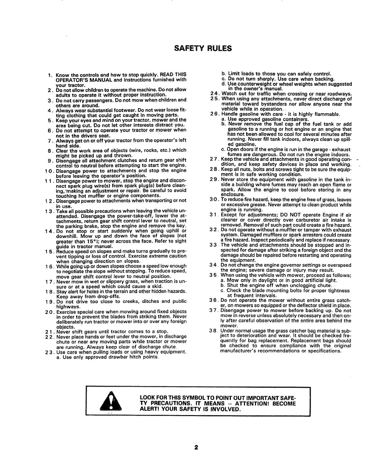
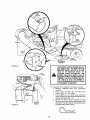
LOOK FORTHIS SYMBOL TO POINT OUT IMPORTANT SAFE-
TY PRECAUTIONS. IT MEANS -- ATTENTION! BECOME
ALERT! YOUR SAFETY IS INVOLVED.
2
CONGRATULATIONS on your purchase of a Sears Craftsman Grass Catcher Attachment° It has been designed, engineered
and manufactured to give you the best possible dependability and performance° Should you experience any problem
you cannot easily remedy, please contact your nearest Sears Service Department= They have competent, well-trained
technicians and the proper tools to repair this unit_
Please read and retain this manual The instructions will enable you to assemble, operate, and maintain your Craftsman
Grass Catcher properly. Always observe the "SAFETY RULES ""
LIMITED ONE YEAR WARRANTY
For one year from the date of purchase, when this grass catcher attachment is maintained according
to the operating and maintenance instructions in the owner's manual, Sears will repair free of charge
any defect in material or workmanship.
This warranty excludes blade(s) and blade adapter(s), which are expendable and become worn dur-
ing normal use°
This warranty does not cover:
- repairs necessary because of operator abuse or negligence, including the failure
to maintain the equipment according to instructions contained in the owner's
manual; and
grass catcher attachments used for commercial or rental purposes°
WARRANTY SERVICE iS AVAILABLE BY CONTACTING THE NEAREST SEARS SERVICE
CENTER/DEPARTMENT IN THE UNITED STATES° This warranty applies only while this product is
in use in the United States.
This warranty gives you specific legal rights, and you may also have other rights which vary from
state to state°
SEARS, ROEBUCK AND CO., Depto 698/731A Sears Tower, Chicago, IL 60684
3
INDEX
A
Assembly:
Grass Catcher ............................................................ 1 1
Mower ........................................................................ 8
B
Bagging Tips .................................................................... 15
Blade Care ....................................................................... 16
G
Grass Catcher Removal ..................................................... 16
M
Maintenance .................................................................... 16
0
Operation ........................................................................ 15
P
Parts Bag ..................................................................... 5 - 7
R
Repair Parts ..................................................................... 18
S
Safety Rules ...................................................................... 2
Storage ........................................................................... 16
W
Warranty ........................................................................... 3
4
ASSEMBL Y
Know Your Grass Catcher
READ THIS OWNER'S MANUAL BEFORE OPERA TING YOUR GRASS CA TCHERo If you understand
the machine and its operation, you wilt achieve efficient and peak performanqe. While reading the
manual, compare the illustrations with your Grass Catcher to familiarize }/ourself with the location
of various controls and adjustments. Study the operating instructions and safety precautions
thoroughly to insure proper functioning of your Grass Catcher and to prevent injury to yourseff and
others, Be sure to pay strict attention to all notes and cautions; they are included for your safety°
Save this manual for future reference,
Unpacking Instructions
1o Open Carton.
2o Remove Plastic Containers°
3. Remove Corrugated Fillers.
4o Remove Blades, Support Post and Grass Catcher
Cover°
The operation of any tractor can
result in foreign objects thrown into the
eyes, which can result in severe eye
damage° Always wear safety glasses or eye
shields before starting your tractor and
while mowing. We recommend Wide Vision
Safety Mask for over the spectacles or stan-
dard safety glasses, available at Sears Retail
or Catalog Stores.
Mower Deck Hardware Parts Bags
Contents Not Shown Full Size
(2) Lower Blade Saddle
(21 Saddle
(1) Clamp
{1) Latch Pin
(1) Front
Latch Bracket
Mounting Bracket Hardware Parts Bag
Contents Not Shown Full Size
(1) U-Bolt, I/4-20 (1) Latch Pin
(I) Hinge Bracket
QP
(1) Elbow Clamp
(1) End Plug
(!) Bracket Support Pin
m
ASSEMBLY
LOCATION
FRONT
LATCH
BRACKET
AND
MOWER DECK PARTS BAG SHOWN FULL SIZE
RUNNER
LATCH
ASSEMBLY
AND
DISCHARGE
GUARD
BLADES
BAFFLE
CHUTE
EXTENSION
(3) Carriage Bolt, 5/!6-18 x 1
121 Carriage Bolt, 5!16-18 x _62
(3) Locknut, 5/16-18
_lU
Q
12t Locknut, 5/16-18
(2) Hex Bolt, 3/8 - 24 x 1 - 3/4, Gro 5
Q
(2) Lockwasher, 3/8
(2) Washer _406 x 1 x _127/.112
(1) Hex Bolt, 1/4-20 x 1-1/4
Q
(1) Locknut, 1/4-20
(2) Retainer Spring
ASSEMBLY MOUNTING BRACKET PARTS BAG SHOWN FULL SIZE
LOCATION
SUPPORT POST
AND
HOOD HINGE
ELBOW
RETAINER
(2) Formed Washer
(2) Retainer Spring
©
(2) Locknut 5/16-18
6
HOOD
HINGE
U-BOLT
REAR
MOUNTING
BRACKET
ELBOW
(2) Hex Bolt, 1/4-20 x 3/4, Gr_ 5
Q
(2) Locknut, 1/4-20
©
_ (2) Hex Nuts, 1/4 - 20
(4) Washer ,,28 x ,62 x ,06
G
{2) Locknut, 1/4-20
{ 1) Shoulder Bolt
(1) Washer
O
(1) Locknut, 3/8-16
(1) Truss Head Screws
10 - 24 x 1/2
©
(2) Washer No, 10
(t) Acorn Lock Nut
10- 24
GRASS CATCHER CARTON CONTENTS:
(1
(1
(1
(1
(1
{1
{1
11
{t
(1
(1
(1
{t
R,,H_ Container Assembly with Frame
L,H,, Container Assembly with Frame
Plastic Elbow
Plastic Chute Extension
Latch Assembly
R,H, Baffle
U-Bolt
Elbow Shield Assembly
Mower Deck Bag of Hardware
Mounting Bracket Bag of Hardware
Post Assembly
Tube and Handle Assembly
Mounting Bracket
(2) Blades
(1) Hood
(t) Owner's Manual
7
Y
15ARTS IDENTIFICATION
COVER
ELBOW
/f
30 GALLON
CONTAINER
"CLUTCHIBRAKE"
POSITION
FIGURE 2
CHUTE
TUBE
ASSEMBLY
EXTENSION .....4=,-
CHUTE
ASSEMBLY
MOWER 8LADE
CLUTCH LEVER
"DtSENGAGED"
POSITION
IGNITION
KEY
GEAR SH{FT
LEVER
°? o
CHUTE LATCH
PIN ASSEMBLY
To assemble your grass catcher' you will need:
(1) 9/16" wrench (1) screwdriver, 6"
(2) 1/2" wrenches I1) 318" wrench
(2) 7/i6"" wrenches
(1) 7/8" wrench
NOTE: RIGHT HAND (R.HJ AND LEFT HAND (L.H..) ARE
DETERMINED FROM OPERATOR'S POSITION WHILE
SEATED ON THE TRACTOR,
ASSEMBLY-MOWER
READ THE "SAFETY RULES" CAREFULLY
BEFORE OPERATING YOUR GRASS
CATCHER.
DO NOT OPERATE MOWER WiTH GRASS
CATCHER ASSEMBLY PARTIALLY
INSTALLED.
..................... ii,lll 'lln I I
All hardware for mower assembly found in bag labetea
"Mower Deck Hardware".
I., Turn ignition key (Fig, 2) to "'OFF"position_
..................... ,,,, ,,,,,, ,,, ,,,,,,,,,
REMOVE KEY TO PREVENT UNAUTHOR-
IZED USE_
MAKE ABSOLUTELY SURE THE BLADES
AND ALL MOVING PARTS HAVE COM-
PLETELY STOPPED,
2_ Push clutch-brake pedal completely into "'BRAKE'"
position (Fig, 2),
8
3_ Move gearshift lever (Fig,_2) to "'Neutral-position.
4. Place parking brake (Fig° 2) in "'ENGAGED" posi-
tion,, Raise parking brake lever and hold in "'ENGAG_
EL)" position° Release clutch-brake pedal
5., Disengage mower blade clutch lever (Fig° 2 - Inset),,
J',.........
DISCONNECT THE SPARK PLUG WIREIS)
FROM THE SPARK PLUG(S) AND KEEP
WIRE(S) AWAY FROM THE PLUG(S) TO
PREVENT INJURY FROM ACCIDENTAL
STARTING.
6_ Remove mower from tractor., Refer "'To Remove
Mower" in your tractor owners manual. For ease
of assembly, turn the mower upside down,
7_ Using a 9/16" wrench remove the bolts,
Iockwashers and washers securing the mower
blades to the mandrel assemblies° Save hardware
for later use when mower is used without grass
catcher,
B, Mount grass catcher blades, lower blade saddles,
upper blade saddles and mower blades to mandrel
assemblies (Fig. 3) using: two 3/8 - 24 x i - 3/4
hex bolts gro5, two Iockwashers and two washers
(shown full size below)° Grass catcher blades, lower
blade saddles, upper blade saddles and hardware
furnished with grass catcher_
MOWER
MANDREL
UPPER BLADE
SADDLE
\
MANDREL
ASSEMBLY
FIGURE 3 -
a_
Return mower blade (Fig, 3) to original position
against mandrel assembly,,
b, Place upper blade saddle and lower blade sad-
dle (Fig, 3) on mower blade° NOTE: Position
flanges as shown in Fig, 3.
c, Place grass catcher blade in lower blade saddle,
NOTE: Be sure pointed edges of grass catcher
blade are facing upward (Fig, 3).
d_
Secure grass catcher blade assembly to mandrel
assembly using hex bolt, lockwasher and
washer (Fig. 3), Tighten securelyr NOTE: Lower
blade saddle must be seated inside upper blade
saddle (Fig,,3- lnset)_ Repeat procedure for other
blade.,
i, , ......................................
ALWAYS USE GRADE 5 HEAT TREATED 1
BOLTS TO ATTACH BLADES° CHECK |
BOLTS IN BLADES OCCASIONALLY TO |
MAKE SURE BOLTS ARE TIGHT. TORQUE |
BOLTS 27 - 35 FT. LBSo
/
n ,. ii ....................................... ill
A GRADE 5 HEAT TREATED BOLT CAN BE
IDENTIFIED BY THREEE LINES INDICATED
ON THE BOLT HEAD AS SHOWN AT LEFT,
,q
R H BAFFLE
/
LOWER BLADE
SADDLE
FIGURE 4
\
R H FOOTREST
DISCHARGE
JARD
9o Using a 1/2" wrench remove hardware "D" (Fig.
5 - Inset) securing discharge guard to mower hous-
ing, Hardware may be discarded°
10o Using a 1/2" wrench remove hardware "A", "'B"
and "'C" (Fig. 6) securing R.H. runner to mower
housing, Hardware may be discarded.
1 1_ Place R,H. baffle (Fig° 4) on lip of mower housing,
Secure R,Ho runner to R,H, baffle and mower hous-
ing using: one 5/16 carriage bolt and one 5/16
locknut (shown full size below). NOTE: Do not
tighten, RH. baffle and hardware furnished with
grass catcher_
FIGURE 5
MOWER
HOUSING
1 2, Secure R,H, baffle to mower housing using: one
clamp, one 1/4 hex bolt and one 1/4 locknut {shown
full size below) Clamp and hardware furnished with
grass catcher,
a_
11ttll!11illll] Q
Place clamp (Fig° 7) over hole in RHo baffle (Fig.
7) Bolt head to underside of mower housing,.
Tighten securety_
13_ Assemble front latch bracket to top of R.H, runner
(Fig. 8) using: two 5/16 carriage bolts and two 5/16
locknuts (shown full size below),. Bolt heads to
underside of mower housing. Tighten securely.
Front latch bracket and hardware furnished with
grass catcher. NOTE: Tighten hardware assembl-
ed in step 11_
FIGURE 6
FIGURE 7 10
14o Attach discharge guard to latch assembly and
mower housing [Fig. 8) using two 5/16 carriage
bolts and two 5/16 locknuts (shown furl size
below). Bolt heads to underside of mower housing_
Tighten securely, Hardware furnished with grass
catcher,
15_ Reattach mower to tractor, Refer to "Mower In-
stallation"in your tractor owners manual
ASSEMBLY-GRASS CATCHER
Al! hardware for grass catcher assembly is found in bag
labeled "'Mounting Bracket Hardware",
! ,, Locate u_bolt in parts bag_ Place two 1/4 hex nuts
and two washers (shown full size below) on u-bolt
(Fig, 9 - insetL
oQ
NOTE: Run nuts on u-bolt as shown in illustration belowr
U-bolt and hardware furnished with grass catcher.
D__ACHDARGE" _ _
BOLTS FRONT
LATCH
BRACKET
LATCH
ASSEMBLY
FIGURE 8
U-BOLT
HEX
NUT
2. Insert u-bolt through slot in drawbar as shown in
Figo 9,
3. Place the rear mounting bracket (Fig, 9) on u-bolt
and secure with two washers and two 1/4 locknuts
(shown furl size below). Tighten finger tight, Rear
mounting bracket and hardware furnished with
grass catcher.
4, Secure the rear mounting bracket to the drawbar
(Fig° 9) using: one shoulder bolt, one washer and
one 3/8 locknut (shown full size below), Tighten
securely. NOTE: Tighten hardware assembled in
step 3. Hardware furnished with grass catcher,
WASHERS
WASHERS
t/4 LOCKNUTS
HEX NUTS
U-BOLT
DRAWBAR
SHOULDER
BOLT
3/8 LOCKNUT
REAR
MOUNTING
BRACKET
FIGURE 9
11
SUPPORT POST
ASSEMBLY
5. Assemble the support post assembly to the rear
mounting bracket (Fig. 10) using support bracket
pin and retainer spring, Retainer spring shown full
size below. Support post, latch pin and retainer
spring furnished with bagger.
/
RETAINER
SPRING
REAR
MOUNTING
BRACKET
FIGURE 10
J
SUPPORT
BRACKET
PIN
6, Install end plug (Fig° 1t) on elbow support tube,, End
plug furnished with bagger_
7_ Mount the elbow retainer and the elbow shield to
the elbow support tube (Fig. 1 1) using: two form-
ed washers and two 5/16 locknuts (shown full size
below). NOTE: Do not tighten, Elbow retainer,
elbow shield and hardware furnished with bagger_
FORMED
SUPPORT POST
ASSEMBLY
ELBOW
RETAINER
8. Locate the small hole in one end of the elbow, Slide
this end of the elbow through elbow retainer (Fig_
12 - Inset), Secure elbow to elbow retainer using:
one clip, one screw, two washers, and one acorn
nut_ NOTE: Mount clip in hole located 2 - I/2"" from
edge of elbow. Hardware shown fult size below.
Head of screw and one flat washer mount to the
inside of elbow,, Position clip with closed end
facing tube opening as shown in Fig,, t2 - Inset,
Tighten securely. NOTE: Tighten hardware
assembled in step 7,, Elbow and hardware furnish-
ed with grass catcher,
9 ,. Flip seat forward,
FIGURE 11
12
t/4 LOCKNUTS TOP 1/4 LOCKNUTS
SPRING
HOOD
_.,., HINGE
SUPPORT POST
1/4 HEX
ASSEMBLY )LTS
1/4 HEX BOLTS
10o Mount hood hinge to grass catcher cover using (2)
I/4 hex bolts and (2) 1/4 Iocknuts (shown full size
below) (Fig,, 12 - upper inset).
Q
1 I Mount top cover to support post (Fig. 12) using
latch pin and retainer spring Retainer spring shown
full size below. Latch pin and retainer spring furnish-
ed with _rass catcher_
FIGURE 12
12_
I
Position the grass catcher container assemblies on-
to the support posts through the "'L "" slots (Fig, !3
- Inset)
BRACKET
_-"L" SLOT
SUPPOR! POST
LY
SUPPORT POST
ASSEMBLY
13
t
GRASS
CATCHER
CONTAINER
°ASSEMBLIES
!
t
FIGURE 13
TUBE
•HANDLE
LATCF
.:FLECTOR
SHIELD
CHUTE
EXTENSION
CHUTE
PIN
ELBOW
CHUTE
TUBE
FIGURE 14
LATCH
-.\
CONTAtNE_
i I
FIGURE 15
PIN
LATCH
ASSEMBLY
ELBOW
SHIELD
EXTENSION
TOP
)VER
LATCH
FRONT
- LATCH
_BRACKET
"_'_"_CHUTE
EXTENSION
ASSEMBLY
ASSEMBLY
i,,i,,,n, ....................... i hill:
YOUR SPRING LOADED MOWER DEFLEC-
TOR SHIELD {FIG, 14) MUST NOT BE
REMOVED_ SIMPLY ROTATE IT UP AND
HOLD IN UP POSITION WHILE AT-
TACHING CHUTE EXTENSION. THE
MOWER DEFLECTOR SHIELD CAN BE
RELEASED TO REST AGAINST CHUTE EX-
TENSION. THIS WILL ASSURE DEFLEC-
TOR SHIELD IS STILL ON MOWER IF
CHUTE EXTENSION OF GRASS CATCHER
ATTACHMENT IS REMOVED_
13, Assemble chute extension to mower housing,
a_ Remove cardboard insert from rectangular
opening.
b, Insert chute extension pin into flont latch
bracket (Fig_ 14 - R.Ho Inset)_
c, Lift up slightly on Loll, side of chute extension
lining up spacer located on latch assembly with
rear latch bracket (Fig. 14),
d, Secure R_H side of chute extension to front
latch bracket using: retainer spring (shown fur
size below), Chute extension and retainer spring
furnished with grass catchet_
14
e_ Secure LH, side of chute extension to latch
assembly using: latch pin and retainer spring
(Fig. t4 - Lower Inset),. Retainer spring shown
furl size below. Latch pin and retainer spring fur-
nished with grass catcher.
14. Place chute tube (Fig. 14) in elbow° Slide chute tube
over chute extension (Fig, 14) and secure by hook-
ing latch over latch pin (Fig. 14 - Upper Inset),
15. Close top cover,, NOTE: Be sure elbow shield is on
inside of top cover (Fig, !4),
OPERATION
' cONNEcT SPARKPLUG WIRE(Si TO sPARKI
= PLUG(S). BE CAREFUL TO AVOID !
* TOUCHING HOT MUFFLER OR ENGINE
J" COMPONENTS ......... J
Follow the mower operation instructions in your tractor
owners manual°
When operating your grass catcher on a lawn where
grass and leaf bagging equipment has not been used, you
are picking up thatch and debris that has accumulated
for long periods of time, The amount collected and the
total time of operation may be greater than you will ex-
perience with regular use of your grass catcher,
A Do.oTOPE.,TE.OW .W,,,O.,SSI
I
INSTALLED.
TIPS FOR IMPROVED RAGGING OPERATION:
1o Place throttle control at full throttle_
2, Select a gear low enough to give good mower cut-
ting performance, good quality cut and good bagg-
ing performance_ NOTE: it may be necessary to
overlap width of cut to suit your conditions.
. VIEW FROM TOP---TOP COVER OPEN
HAND
GRASS CATCHER
ASSEMBLY
X
3_ If grass is extremely tell, it should be mowed twice.
The first time relatively high, the second time to
desired height, NOTE: Use LoH_side of mower for
trimming.
4 ,, Plastic lawn bags can be inserted inside grass cat-
cher containers for ease of debris disposal
................. i , i , iil, l,i,ji L I_ I , ii I ,1
DISENGAGE MOWER WHEN CROSSING
GRAVEL SURFACES AND ANY CONDI-
TIONS WHERE THROWN OBJECTS
COULD BE A HAZARD.
DO NOT ATTEMPT TO VACUUM UP
CANS OR OTHER POTENTIALLY HAZAR-
DOUS PROJECTILES,
5 ,,Avoid cutting wet grass or in the morning while the
dew is still heavy. Grass clippings collected under
these conditions tend to be sticky and adhere to the
walls of the flow path causing clogging.
6o Keep clear grass catcher chute tube clean so that
clogging can be detected°
DISENGAGE BLADES AND STOP ENGINE
BEFOREOPENING COVER.
INSTALL CONTAINERS BEFORE
OPERATING.
CLOSE COVER BEFORE STARTING
MOWER.
KEEP CLEAR GRASS CATCHER CHUTE
TUBE CLEAN TO DETECT CLOGGING° IF
CLOGGING OCCURS, DISENGAGE
BLADES, SHIFT INTO NEUTRAL, ENGAGE
THE PARKING BRAKE AND SHUT OFF THE
ENGINE BEFORE REMOVING TUBE TO
CLEAR OBSTRUCTION.
If the grass catcher fails to pick up cut grass or leaves,
it is an indication that clogging has occurred in the
system (See Step 1 below) or that the grass catcher con-
tainers are full (See step 2 below)°
1. Stop tractor and mower and remove clogged grass.
Refer to "'Caution" above.
2. Disengage blades, shift into neutral, engage the
parking brake and stop the engine°
a. Unlatch cover (Fig, 15)°
b o Remove LHo grass catcher assembly., Stand at
position "'X'" and grasp grass catcher at points
"'A" and "'B'" and lift off (Fig. 16)_
c, After removing LH. assembly, stand at position
"'Y", grasp R,H, catcher assembly at points "'C'"
and "D'" and lift off, Reverse procedure to
replace,
d. Close cover and latch,
NOTE: If experiencing abnormal discharge when
operating mower without grass catcher attachment it
may be necessary to remove grass catcher blades,
FIGURE 16 15
MAINTENANCE
For any adjustment, inspection or maintenance:
1. Push clutch-brake pedal completely into "BRAKE"
position..
2_ Move gear shift lever to "NEUTRAL" position.
3o Place parking brake in "'ENGAGED" position. Raise
park#_g brake lever and hold in "ENGAGED" posi-
tion., Release clutch-brake pedal.
4, Move throttle control lever to "'SLOW" position.
5. Disengage mower blade clutch le(mr.
6. Turn ignition key to "OFF" position.,
7. Remove Key,
............ MAI(E'"'""ABSOLuTELY SURE THE BLADES
AND ALL MOVING PARTS HAVE COM-
PLETELY STOPPED.
DISCONNECT THE SPARK PLUG WIRE(S)
FROM THE SPARK PLUG(S) AND KEEP
WIRE(S) AWAY FROM THE PLUG(S} TO PRE-
VENT INJURY FROM ACCIDENTAL STAR-
TING. BE CAREFUL 1'O AVOID TOUCHING
HOT MUFFLER OR ENGINE COMPONENTS,
BLADE CARE
To ensure satisfactory operation, it is recommended that
before the start of each mowing season, the old blades
be discarded and replaced with new blades, Blades can
be purchased at all Sears Service Centers and most retail
stores°
TO REMOVE GRASS CATCHER
Reverse steps I thru 15 under "Assembly - Grass
Catcher", pages 7- 11.
YOUR CONTAINERS ARE OF VERY
DURABLE MATERIAL, HOWEVER, IN THE
EVENT OF EXCESSIVE WEAR OR
DAMAGE, REPLACE IMMEDIATELY. THE
REPLACEMENT CONTAINER SHOULD
COMPLY WITH THE ORIGINAL
MANUFACTURED SPECIFICATIONS IN
ORDER TO INSURE PROPER PERFOR-
MANCE AND PRODUCT SAFETY,
STORAGE
When grass catcher is to be stored for a period of time,
clean it thoroughly, remove aft dirt, grass, leaves, etc.
Store in a clean, dry place°
i lllllll i l i, i,i ill=ll/lll,lllll
REPLACE IMMEDIATELY ANY PARTS
THAT SHOW WEAR OR DETERIORATION,
ESPECIALLY PARTS WHICH CONTAIN
A THE FLOW OF MATERIAL FROM THEMOWER, ALSO, CHECK THE CONDITION
OF FASTENERS THAT KEEP THESE
PARTS IN A SAFE POSITION DURING
OPERATION.
16
8ENVa_E MaTSS
17
REPAIR PARTS
CRAFTSMAN GRASS CATCHER FOR SIDE DISCHARGE MOWER--MODEL NUMBER
4
56
5
A B C D
53 6 I_ 38
38 _ 35
9
0
62
f
28 23
26
21
t7
/
E
REPAIR PARTS
CRAFTSMAN GRASS CATCHER FOR SIDE DISCHARGE MOWER-MODEL NUMBER 917.249393
KEY PART DESCRIPTION KEY PART DESCRIPTION
NO. NO. NO_ NO,
3 6 57734
1 110334X Cover - Top 37 41945
2 86578 Bracket - Hinge 3 8 STD541425
3 110441X Strip - Foam 39 STD533110
4 106815X Strip - Foam 40 76507
5 120176X Container _ 30 GaL 41 STD522512
6 66238 Bolt - Carriage 5/16 _ 18 x 5t8 42 85891
7 I04369X Plug _End 43 74316
8 83553 Clip - Elbow 44 STD551137
9 86558 Retainer - Elbow 45 120101X
10 85902 Spring - Retainer 4 6 85925
1 1 120097X Pin - Latch 4 7 STD523107
12 85903 Spring _Retainer 48 120t03X363
13 110254X363 Post _ Support 49 121109X
! 4 62361 Bolt - Shoulder 50 86987
15 86562 Bracket - Mounting 51 STD551110
16 120096XO04 Bracket Latch, Front 5 2 85463
17 STD541437 * Nut - Lock 3/8 - 16 53 71615
18 86626 U-Bolt 114 - 20 54 109808X
19 STD541025 * Nut _ Hex 114 - 20 55 120108X363
20 85723 Washer _Flat 9/32 56 120109X363
2 1 110257X Elbow 58 2029J
2 3 !O4415X Tube =Chute 5 9 12049
24 120t0OX Extension - Chute 6 1 120203X
2 5 120102X004 Latch Bracket - Chute, Rear 6 2 110255X363
26 85937 Baffle - R,H_ 64 60867
28 85936 Clamp 6 5 120105X
29 85893 Saddle _ Lower Blade --- 104419X
30 104418X Blade _ Lower _-- 120094X
3 1 86543 Pin - Support Bracket
33 74291010 Screw - Truss Head 10-24 x 5/6
35 STD541431 *Nut _ Lock 5!16 - 18
,1
Washer, Formed
Screw - Truss Heed 10-24 x 1/2
* Nut - Lock 1/4 - 20
* Bolt - Carriage 5116 - 18 x 1
Washer 11/32
* Bolt - Hex, 1/4- 20 x 1 - 114
Bolt- Hex, 318 - 24 x 1 - 3/4 Gr. 5
Washer _406 x 1 x .127A112
* Washer - Lock, 3/8
Baffle - Chute
Pin Assembly - Latch, Chute
"Bolt - Hex 5!16 * 18 x 3/4 Gr, 5
Latch Assembly
Handle Assembly (lncL Key # 61)
Saddle - Upper Blade
Washer _Lock #10
Decal - Danger
Bolt - Hex 1/4 * 20 x 3!4
Latch
Assembly _ Frame, R.Ho
Assembly - Frame, L.H,
Nut _Weld
Washer, Flat
Stud -Latch
Shield _Elbow
Nut - Acorn # 10 - 24
Screw - Plastite 1t4 * 10 x 3/4
Bag - Trash, 30 GeL, 15 MiL
Manual - Owners
"STANDARD HARDWARE--PURCHASE LOCALLY
E F G H J K L M
42 47 47 37 33
38 @ 59 @ 40 @ 40 @ 59 59
35 (_ 43 @ 59 _ 59 (_ 59
44 @64 ®4o @51
35 (_58
N R
_61 _ 65
20
m
_/AURS
OWNERS
MANUAL
MODEL NO.
917.249393
HOW TO ORDER
REPAmRPARTS
CRRFTSMRN®
GRASS CATCHER
The Model Number will be found on the Model Plate attached to
the Support PosL Always provide the Model Number* when re-
questing service or repair parts for your Craftsman Grass Catcher.
All parts listed herein may be ordered from any Sears Service
Center/Departments and most Sears stores.
WHEN ORDERING REPAIR PARTS, AL WAYS GIVE THE FOLLOW-
ING INFORMATION:
o THE PART NUMBER
t THE PART DESCRIPTION
= THE MODEL NUMBER
= THE NAME OF MERCHANDISE
Your Sears merchandise has added value when you consider Sears
has service units nationwide staffed with Sears trained technicians
having the parts, tools and the equipment to insure that we meet
our pledge to you, "We Service What We Sell"o
Sears, Roebuck and Co., Chicago, IL 60684 U,S.A.
p_ No. 12o=_x RL=v.I e41111SS
  • Page 1 1
  • Page 2 2
  • Page 3 3
  • Page 4 4
  • Page 5 5
  • Page 6 6
  • Page 7 7
  • Page 8 8
  • Page 9 9
  • Page 10 10
  • Page 11 11
  • Page 12 12
  • Page 13 13
  • Page 14 14
  • Page 15 15
  • Page 16 16
  • Page 17 17
  • Page 18 18
  • Page 19 19
  • Page 20 20

Craftsman 917.249393 Owner's manual

Category
Garden tools
Type
Owner's manual
This manual is also suitable for

Craftsman 917.249393 is a Grass Catcher Attachment, designed to collect grass clippings while you mow your lawn. It features a durable bag to hold the clippings, and a sturdy frame to keep it in place. The Grass Catcher Attachment is easy to install and remove, and it can be used with most Craftsman mowers. With its help, you can keep your lawn looking neat and tidy, and reduce the amount of time you spend raking or bagging grass clippings.

Ask a question and I''ll find the answer in the document

Finding information in a document is now easier with AI