National Instruments NI USB-6008/6009 User manual
- Category
- Supplementary music equipment
- Type
- User manual

USER GUIDE AND SPECIFICATIONS
NI USB-6008/6009
This user guide describes how to use the National Instruments
USB-6008/6009 data acquisition (DAQ) devices and lists specifications.
Introduction
The NI USB-6008/6009 provides connection to eight analog input (AI)
channels, two analog output (AO) channels, 12 digital input/output (DIO)
channels, and a 32-bit counter with a Full-Speed USB interface.
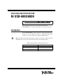
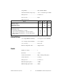
Note This manual revision updates naming conventions to reflect the conventions used in
NI-DAQmx. Table 1 notes the correlation between the old and updated names.
Table 1. Digital Output Driver Type Naming Conventions
Hardware Functionality NI-DAQmx Terminology
Open-drain Open collector
Push-pull Active drive
ni.com/manuals
DeutschFrançais

NI USB-6008/6009 User Guide and Specifications 2 ni.com
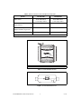
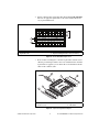
Figure 1. NI USB-6008/6009 Top View
Figure 2. NI USB-6008/6009 Back View
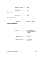
Table 2. Differences Between the NI USB-6008 and NI USB-6009
Feature NI USB-6008 NI USB-6009
AI Resolution 12 bits differential,
11 bits single-ended
14 bits differential,
13 bits single-ended
Maximum AI Sample Rate,
Single Channel
*
10 kS/s 48 kS/s
Maximum AI Sample Rate,
Multiple Channels (Aggregate)
*
10 kS/s 48 kS/s
DIO Configuration Open collector Open collector or active drive
*
System dependent.
1 USB Cable Strain Relief
NI USB-6009
8 Inputs, 14-bit, Multifunction I/O
32 Digital 17
1 Analog 16
1

© National Instruments Corporation 3 NI USB-6008/6009 User Guide and Specifications
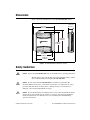
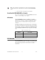
Dimensions
Figure 3 illustrates the dimensions of the NI USB-6008/6009 device.
Figure 3. NI USB-6008/6009 in Millimeters (Inches)
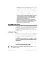
Safety Guidelines
Caution Operate the NI USB-6008/6009 only as described in these operating instructions.
The following section contains important safety information that you must
follow when installing and using the NI USB-6008/6009.
Caution Do not operate the NI USB-6008/6009 in a manner not specified in this
document. Misuse of the device can result in a hazard. You can compromise the safety
protection built into the device if the device is damaged in any way. If the device is
damaged, contact National Instruments for repair.
Caution Do not substitute parts or modify the device except as described in this document.
Use the device only with the chassis, modules, accessories, and cables specified in the
installation instructions. You must have all covers and filler panels installed during
operation of the device.
81.81 mm
(3.221 in.)
76.09 mm
(2.996 in.)
63.50 mm
(2.500 in.)
72.65 mm
(2.860 in.)
85.09 mm
(3.350 in.)
23.19 mm
(0.913 in.)
NATIONAL
INSTRUMENTS

NI USB-6008/6009 User Guide and Specifications 4 ni.com
Caution Do not operate the device in an explosive atmosphere or where there may be
flammable gases or fumes. If you must operate the device in such an environment, it must
be in a suitably rated enclosure.
If you need to clean the device, use a dry cloth. Make sure that the device
is completely dry and free from contaminants before returning it to service.
Operate the device only at or below Pollution Degree 2. Pollution is foreign
matter in a solid, liquid, or gaseous state that can reduce dielectric strength
or surface resistivity. The following is a description of pollution degrees:
• Pollution Degree 1 means no pollution or only dry, nonconductive
pollution occurs. The pollution has no influence.
• Pollution Degree 2 means that only nonconductive pollution occurs in
most cases. Occasionally, however, a temporary conductivity caused
by condensation must be expected.
• Pollution Degree 3 means that conductive pollution occurs, or dry,
nonconductive pollution occurs that becomes conductive due to
condensation.
You must insulate signal connections for the maximum voltage for which
the device is rated. Do not exceed the maximum ratings for the device. Do
not install wiring while the device is live with electrical signals. Do not
remove or add connector blocks when power is connected to the system.
Avoid contact between your body and the connector block signal when hot
swapping modules. Remove power from signal lines before connecting
them to or disconnecting them from the device.
Operate the device at or below the Measurement Category I
1
. Measurement
circuits are subjected to working voltages
2
and transient stresses
(overvoltage) from the circuit to which they are connected during
measurement or test. Measurement categories establish standard impulse
withstand voltage levels that commonly occur in electrical distribution
systems. The following is a description of measurement categories:
• Measurement Category I is for measurements performed on circuits
not directly connected to the electrical distribution system referred to
as MAINS
3
voltage. This category is for measurements of voltages
from specially protected secondary circuits. Such voltage
measurements include signal levels, special equipment, limited-energy
parts of equipment, circuits powered by regulated low-voltage sources,
and electronics.
1
Measurement Category as defined in electrical safety standard IEC 61010-1. Measurement Category is also referred to as
Installation Category.
2
Working Voltage is the highest rms value of an AC or DC voltage that can occur across any particular insulation.
3
MAINS is defined as a hazardous live electrical supply system that powers equipment. Suitably rated measuring circuits may
be connected to the MAINS for measuring purposes.

© National Instruments Corporation 5 NI USB-6008/6009 User Guide and Specifications
• Measurement Category II is for measurements performed on circuits
directly connected to the electrical distribution system. This category
refers to local-level electrical distribution, such as that provided by a
standard wall outlet (for example, 115 V for U.S. or 230 V for Europe).
Examples of Measurement Category II are measurements performed
on household appliances, portable tools, and similar E Series devices.
• Measurement Category III is for measurements performed in the
building installation at the distribution level. This category refers to
measurements on hard-wired equipment such as equipment in fixed
installations, distribution boards, and circuit breakers. Other examples
are wiring, including cables, bus-bars, junction boxes, switches,
socket-outlets in the fixed installation, and stationary motors with
permanent connections to fixed installations.
• Measurement Category IV is for measurements performed at the
primary electrical supply installation (<1,000 V). Examples include
electricity meters and measurements on primary overcurrent
protection devices and on ripple control units.
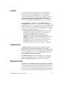
Related Documentation
Each application software package and driver includes information about
writing applications for taking measurements and controlling measurement
devices. The following references to documents assume you have
NI-DAQmx 8.7 or later, and where applicable, version 7.1 or later of the
NI application software.
NI-DAQmx for Windows
The DAQ Getting Started Guide describes how to install your NI-DAQmx
for Windows software, how to install your NI-DAQmx-supported DAQ
device, and how to confirm that your device is operating properly. Select
Start»All Programs»National Instruments»NI-DAQ»DAQ Getting
Started Guide.
The NI-DAQ Readme lists which devices are supported by this version of
NI-DAQ. Select Start»All Programs»National Instruments»NI-DAQ»
NI-DAQ Readme.
The NI-DAQmx Help contains general information about measurement
concepts, key NI-DAQmx concepts, and common applications that are
applicable to all programming environments. Select Start»All Programs»
National Instruments»NI-DAQ»NI-DAQmx Help.
Note For information about non-Windows operating system support, refer to ni.com/
info
and enter BaseGSGML.

NI USB-6008/6009 User Guide and Specifications 6 ni.com
LabVIEW
If you are a new user, use the Getting Started with LabVIEW manual
to familiarize yourself with the LabVIEW graphical programming
environment and the basic LabVIEW features you use to build data
acquisition and instrument control applications. Open the Getting Started
with LabVIEW manual by selecting Start»All Programs»National
Instruments»LabVIEW»LabVIEW Manuals or by navigating to the
labview\manuals directory and opening LV_Getting_Started.pdf.
Use the LabVIEW Help, available by selecting Help»Search the
LabVIEW Help in LabVIEW, to access information about LabVIEW
programming concepts, step-by-step instructions for using LabVIEW, and
reference information about LabVIEW VIs, functions, palettes, menus, and
tools. Refer to the following locations on the Contents tab of the LabVIEW
Help for information about NI-DAQmx:
• Getting Started»Getting Started with DAQ—Includes overview
information and a tutorial to learn how to take an NI-DAQmx
measurement in LabVIEW using the DAQ Assistant.
• VI and Function Reference»Measurement I/O VIs and
Functions—Describes the LabVIEW NI-DAQmx VIs and properties.
• Taking Measurements—Contains the conceptual and how-to
information you need to acquire and analyze measurement data in
LabVIEW, including common measurements, measurement
fundamentals, NI-DAQmx key concepts, and device considerations.
LabWindows/CVI
The Data Acquisition book of the LabWindows/CVI Help contains
measurement concepts for NI-DAQmx. This book also contains
Taking an NI-DAQmx Measurement in LabWindows/CVI, which includes
step-by-step instructions about creating a measurement task using the DAQ
Assistant. In LabWindows
™
/CVI
™
, select Help»Contents, then select
Using LabWindows/CVI»Data Acquisition.
The NI-DAQmx Library book of the LabWindows/CVI Help contains
API overviews and function reference for NI-DAQmx. Select Library
Reference»NI-DAQmx Library in the LabWindows/CVI Help.
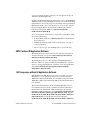
Measurement Studio
If you program your NI-DAQmx-supported device in Measurement Studio
using Visual C++, Visual C#, or Visual Basic .NET, you can interactively
create channels and tasks by launching the DAQ Assistant from MAX or
from within Visual Studio .NET. You can generate the configuration code
based on your task or channel in Measurement Studio. Refer to the DAQ
Assistant Help for additional information about generating code. You also

© National Instruments Corporation 7 NI USB-6008/6009 User Guide and Specifications
can create channels and tasks, and write your own applications in your
ADE using the NI-DAQmx API.
For help with NI-DAQmx methods and properties, refer to the NI-DAQmx
.NET Class Library or the NI-DAQmx Visual C++ Class Library included
in the NI Measurement Studio Help. For general help with programming in
Measurement Studio, refer to the NI Measurement Studio Help, which is
integrated with the Microsoft Visual Studio .NET help. To view this
help file in Visual Studio. NET, select Measurement Studio»
NI Measurement Studio Help.
To create an application in Visual C++, Visual C#, or Visual Basic .NET,
follow these general steps:
1. In Visual Studio .NET, select File»New»Project to launch the New
Project dialog box.
2. Find the Measurement Studio folder for the language you want to
create a program in.
3. Choose a project type. You add DAQ tasks as a part of this step.
ANSI C without NI Application Software
The NI-DAQmx Help contains API overviews and general information
about measurement concepts. Select Start»All Programs»National
Instruments»NI-DAQ»NI-DAQmx Help.
The NI-DAQmx C Reference Help describes the NI-DAQmx Library
functions, which you can use with National Instruments data acquisition
devices to develop instrumentation, acquisition, and control applications.
Select Start»All Programs»National Instruments»NI-DAQ»
NI-DAQmx C Reference Help.
.NET Languages without NI Application Software
With the Microsoft .NET Framework version 1.1 or later, you can use
NI-DAQmx to create applications using Visual C# and Visual Basic
.NET without Measurement Studio. You need Microsoft Visual Studio
.NET 2003 or Microsoft Visual Studio 2005 for the API documentation
to be installed.
The installed documentation contains the NI-DAQmx API overview,
measurement tasks and concepts, and function reference. This help is
integrated into the Visual Studio .NET documentation. To view the
NI-DAQmx .NET documentation, go to Start»All Programs»National
Instruments»NI-DAQ»NI-DAQmx .NET Reference Help. Expand
NI Measurement Studio Help»NI Measurement Studio .NET Class
Library»Reference to view the function reference. Expand
NI Measurement Studio Help»NI Measurement Studio .NET Class

NI USB-6008/6009 User Guide and Specifications 8 ni.com
Library»Using the Measurement Studio .NET Class Libraries to
view conceptual topics for using NI-DAQmx with Visual C# and
Visual Basic .NET.
To get to the same help topics from within Visual Studio, go to
Help»Contents. Select Measurement Studio from the Filtered By
drop-down list and follow the previous instructions.
Device Documentation and Specifications
Documentation for supported devices and accessories, including PDF
and help files describing device terminals, specifications, features, and
operation are on the NI-DAQmx CD that includes Device Documentation.
Insert the CD, open the Device Documentation directory, and double-click
the Device Documents shortcut for your language to find, view, and print
device documents.
Note You can also download these documents at ni.com/manuals.
NI-DAQmx Base (Linux/Mac OS X/LabVIEW PDA 8.x )
The NI-DAQmx Base Getting Started Guide describes how to install your
NI-DAQmx Base software, your NI-DAQmx Base-supported DAQ device,
and how to confirm that your device is operating properly. In Windows,
select Start»All Programs»National Instruments»NI-DAQmx Base»
Documentation»NI-DAQmx Base Getting Started Guide.
Getting Started with NI-DAQmx Base for Linux and Mac Users describes
how to install your NI-DAQmx Base software, your NI-DAQmx
Base-supported DAQ device, and how to confirm that your device is
operating properly on your Mac/Linux machine.
The NI-DAQmx Base Readme lists which devices are supported by this
version of NI-DAQmx Base. In Windows, select Start»All Programs»
National Instruments»NI-DAQmx Base»DAQmx Base Readme.
The NI-DAQmx Base VI Reference Help contains VI reference and general
information about measurement concepts. In LabVIEW, select
Help»NI-DAQmx Base VI Reference Help.
The NI-DAQmx Base C Reference Help contains C reference and general
information about measurement concepts. In Windows, select Start»All
Programs»National Instruments»NI-DAQmx Base»Documentation»
C Function Reference Help.
Note All NI-DAQmx Base documentation for Linux is installed at /usr/local/
natinst/nidaqmxbase/documentation
.

© National Instruments Corporation 9 NI USB-6008/6009 User Guide and Specifications
Note All NI-DAQmx Base documentation for Mac OS X is installed at
/Applications/National Instruments/NI-DAQmx Base/documentation.
Training Courses
If you need more help getting started developing an application with
NI products, NI offers training courses. To enroll in a course or obtain
a detailed course outline, refer to
ni.com/training.
Technical Support on the Web
For additional support, refer to ni.com/support or zone.ni.com.
Installing the Software
Software support for the NI USB-6008/6009 for Windows Vista/XP/2000
is provided by NI-DAQmx. The DAQ Getting Started Guide, which you
can download at
ni.com/manuals, offers NI-DAQmx users step-by-step
instructions for installing software and hardware, configuring channels and
tasks, and getting started developing an application.
Note For information about non-Windows operating system support, refer to ni.com/
info
and enter BaseGSGML.
Installing Other Software
If you are using other software, refer to the installation instructions that
accompany your software.
Example Programs
The NI-DAQmx CD contains example programs that you can use to get
started programming with the NI USB-6008/6009. Refer to the NI-DAQmx
for USB Devices Getting Started Guide that shipped with your device, and
is also accessible from Start»All Programs»National Instruments»
NI-DAQ, for more information.
The NI-DAQmx Base software ships with example programs you can use
to get started programming with the NI USB-6008/6009. Refer to the
NI-DAQmx Base Getting Started Guide that shipped with your device, and
is also accessible from Start»All Programs»National Instruments»
NI-DAQmx Base»Examples, for more information.
Note For information about non-Windows operating system support, refer to
ni.com/info and enter BaseGSGML.

NI USB-6008/6009 User Guide and Specifications 10 ni.com
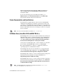
Installing the NI USB-6008/6009 Device
Before installing the device, you must install the software you plan to use
with the device. Refer to the Installing the Software section of this guide
and the documentation included with the software for more information.
Figure 4 shows key functional components of the NI USB-6008/6009.
Figure 4. Device Block Diagram
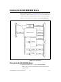
Setting Up the NI USB-6008/6009 Device
Complete the following steps to set up the NI USB-6008/6009:
1. Install combicon screw terminal blocks by inserting them into the
combicon jacks.
P1.<0..3>
P0.<0..7>
Digital I/O Terminal Block
AI <0..7>
AO 0
AO 1
Analog I/O Terminal Block
+2.5 V/CAL
+5 V/200 mA
8 Channel
12/14b ADC
12b DAC
12b DAC
USB Microcontroller
SPI
External
Power
Supply
Vbus
Full-Speed USB Interface
USB
PFI 0

© National Instruments Corporation 11 NI USB-6008/6009 User Guide and Specifications
2. Figure 5 illustrates the signal labels that ship in the NI USB-6008/6009
kit. You can apply the signal labels to the screw terminal blocks for
easy signal identification.
Figure 5. NI USB-6008/6009 Signal Labels
3. Refer to Table 4 and Figures 5 and 6 for signal label orientation and
affix the provided signal labels to the screw terminal blocks. Until the
signal labels are applied, you can insert the screw terminal blocks into
either of the combicon jacks.
Figure 6. Signal Label Application Diagram
1 Terminal Number Labels (Use Both Together)
2 Digital I/O Label
3 Differential Signal Name Label (Use Either)
4 Single-Ended Signal Name Label (Use Either)
1 Overlay Label with Pin Orientation Guides
2 Combicon Jack
3 Signal Labels
4 USB Cable
ANALOG DIGITAL
1
2
3
4
or
90
06
-B
S
U
I
N
O
/
I
n
o
i
t
c
n
uf
i
t
l
u
M
,
t
i
b-
4
1
,
st
upn
I
8
23
lat
igi
D
7
1
1
gol
an
A
6
1
3
2
4
1
2
3

NI USB-6008/6009 User Guide and Specifications 12 ni.com
Note Once you label the screw terminal blocks, you must only insert them into the
matching combicon jack, as indicated by the overlay label on the NI USB-6008/6009
device.
4. Connect the wiring to the appropriate screw terminals.
Connecting the NI USB-6008/6009 to a Computer
Plug one end of the USB cable into the NI USB-6008/6009 and the other
end into an available USB port on the computer.
LED Indicator
The NI USB-6008/6009 device has a green LED next to the USB
connector. The LED indicator indicates device status, as listed in Table 3.
When the device is connected to a USB port, the LED blinks steadily to
indicate that the device is initialized and is receiving power from the
connection.
If the LED is not blinking, it may mean that the device is not initialized or
the computer is in standby mode. In order for the device to be recognized,
the device must be connected to a computer that has NI-DAQmx installed
on it. If your device is not blinking, make sure your computer has the latest
version of NI-DAQmx installed on it, and the computer is not in standby
mode.
I/O Connector
The NI USB-6008/6009 ships with one detachable screw terminal block for
analog signals and one detachable screw terminal block for digital signals.
These terminal blocks provide 16 connections that use 16 AWG to
28 AWG wire.
Table 3. LED State/Device Status
LED State Device Status
Not lit Device not connected or in suspend.
On, not blinking Device connected.
Single-blink Operating normally.

© National Instruments Corporation 13 NI USB-6008/6009 User Guide and Specifications
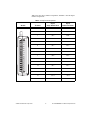
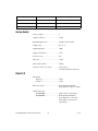
Table 4 lists the analog terminal assignments, and Table 5 lists the digital
terminal assignments.
Table 4. Analog Terminal Assignments
Module Terminal
Signal,
Single-Ended Mode
Signal,
Differential Mode
1 GND GND
2 AI 0 AI 0+
3 AI 4 AI 0–
4 GND GND
5 AI 1 AI 1+
6 AI 5 AI 1–
7 GND GND
8 AI 2 AI 2+
9 AI 6 AI 2–
10 GND GND
11 AI 3 AI 3+
12 AI 7 AI 3–
13 GND GND
14 AO 0 AO 0
15 AO 1 AO 1
16 GND GND
12345678 9 10111213141516

NI USB-6008/6009 User Guide and Specifications 14 ni.com
Table 5. Digital Terminal Assignments
Module Terminal Signal
17 P0.0
18 P0.1
19 P0.2
20 P0.3
21 P0.4
22 P0.5
23 P0 6
24 P0.7
25 P1.0
26 P1.1
27 P1.2
28 P1.3
29 PFI 0
30 +2.5 V
31 +5 V
32 GND
32 31 30 29 28 27 26 25 24 23 22 21 20 19 18 17

© National Instruments Corporation 15 NI USB-6008/6009 User Guide and Specifications
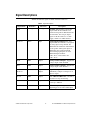
Signal Descriptions
Table 6 describes the signals available on the I/O connectors.
Table 6. Signal Descriptions
Signal Name Reference Direction Description
GND — — Ground—The reference point for the
single-ended AI measurements, bias
current return point for differential mode
measurements, AO voltages, digital
signals at the I/O connector, +5 VDC
supply, and the +2.5 VDC reference.
AI <0..7> Var ie s Input Analog Input Channels 0 to 7—For
single-ended measurements, each signal is
an analog input voltage channel. For
differential measurements, AI 0 and AI 4
are the positive and negative inputs of
differential analog input channel 0.
The following signal pairs also form
differential input channels:
<AI 1, AI 5>, <AI 2, AI 6>, and
<AI3,AI7>.
AO 0 GND Output Analog Channel 0 Output—Supplies the
voltage output of AO channel 0.
AO 1 GND Output Analog Channel 1 Output—Supplies the
voltage output of AO channel 1.
P1.<0..3>
P0.<0..7>
GND Input or
Output
Digital I/O Signals—You can
individually configure each signal as an
input or output.
+2.5 V GND Output +2.5 V External Reference—Provides a
reference for wrap-back testing.
+5 V GND Output +5 V Power Source—Provides +5 V
power up to 200 mA.
PFI 0 GND Input PFI 0—This pin is configurable as either a
digital trigger or an event counter input.

NI USB-6008/6009 User Guide and Specifications 16 ni.com
Analog Input
You can connect analog input signals to the NI USB-6008/6009 through
the I/O connector. Refer to Table 6 for more information about connecting
analog input signals.
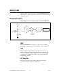
Analog Input Circuitry
Figure 7 illustrates the analog input circuitry of the NI USB-6008/6009.
Figure 7. Analog Input Circuitry
MUX
The NI USB-6008/6009 has one analog-to-digital converter (ADC).
The multiplexer (MUX) routes one AI channel at a time to the PGA.
PGA
The progammable-gain amplifier provides input gains of 1, 2, 4, 5, 8,
10, 16, or 20 when configured for differential measurements and gain
of 1 when configured for single-ended measurements. The PGA gain
is automatically calculated based on the voltage range selected in the
measurement application.
A/D Converter
The analog-to-digital converter (ADC) digitizes the AI signal by
converting the analog voltage into a digital code.
AI
+2.5 V
REF
39.2 kΩ
127 kΩ
30.9 kΩ
PGA
Input Range
Selection
AI FIFO
ADC
MUX

© National Instruments Corporation 17 NI USB-6008/6009 User Guide and Specifications
AI FIFO
The NI USB-6008/6009 can perform both single and multiple A/D
conversions of a fixed or infinite number of samples. A first-in-first-out
(FIFO) buffer holds data during AI acquisitions to ensure that no data
is lost.
Analog Input Modes
You can configure the AI channels on the NI USB-6008/6009 to take
single-ended or differential measurements. Refer to Table 6 for more
information about I/O connections for single-ended or differential
measurements.
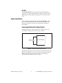
Connecting Differential Voltage Signals
For differential signals, connect the positive lead of the signal to the
AI+ terminal, and the negative lead to the AI– terminal.
Figure 8. Connecting a Differential Voltage Signal
The differential input mode can measure ±20 V signals in the ±20 V range.
However, the maximum voltage on any one pin is ±10 V with respect to
GND. For example, if AI 1 is +10 V and AI 5 is –10 V, then the
measurement returned from the device is +20 V.
AI+
NI USB-6008/6009
AI–
Voltage
Source

NI USB-6008/6009 User Guide and Specifications 18 ni.com
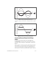
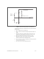
Figure 9. Example of a Differential 20 V Measurement
Connecting a signal greater than ±10 V on either pin results in a clipped
output.
Figure 10. Exceeding ±10 V on AI Returns Clipped Output
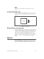
Connecting Referenced Single-Ended Voltage
Signals
To connect referenced single-ended voltage signals (RSE) to the
NI USB-6008/6009, connect the positive voltage signal to the desired
AI terminal, and the ground signal to a GND terminal, as illustrated in
Figure 11.
When no signals are connected to the analog input terminal, the internal
resistor divider may cause the terminal to float to approximately 1.4 V
when the analog input terminal is configured as RSE. This behavior is
normal and does not affect the measurement when a signal is connected.
–5
–10
–15
–20
20
15
10
5
0
Amplitude (V)
AI 1
AI 5
Result
–5
–10
–15
–20
20
15
10
5
0
Amplitude (V)
AI 1
AI 5
Result

© National Instruments Corporation 19 NI USB-6008/6009 User Guide and Specifications
Figure 11. Connecting a Referenced Single-Ended Voltage Signal
Digital Trigger
When an AI task is defined, you can configure PFI 0 as a digital trigger
input. When the digital trigger is enabled, the AI task waits for a rising or
falling edge on PFI 0 before starting the acquisition. To use ai/Start Trigger
with a digital source, specify PFI 0 as the source and select rising or falling
edge.
Analog Output
The NI USB-6008/6009 has two independent AO channels that can
generate outputs from 0–5 V. All updates of AO lines are software-timed.
Analog Output Circuitry
Figure 12 illustrates the analog output circuitry for the NI USB-6008/6009.
Figure 12. Analog Output Circuitry
AI
NI USB-6008/6009
GND
Voltage
Source
REF(+) REF(–)
12-Bit
DAC
Output
Buffer
50 Ω
AO
+5 V
GND

NI USB-6008/6009 User Guide and Specifications 20 ni.com
DACs
Digital-to-analog converts (DACs) convert digital codes to analog
voltages.
Connecting Analog Output Loads
To connect loads to the NI USB-6008/6009, connect the positive lead of the
load to the AO terminal, and connect the ground of the load to a GND
terminal.
Figure 13. Connecting a Load
Minimizing Glitches on the Output Signal
When you use a DAC to generate a waveform, you may observe glitches in
the output signal. These glitches are normal; when a DAQ switches from
one voltage to another, it produces glitches due to released charges. The
largest glitches occur when the most significant bit of the DAC code
changes. You can build a lowpass deglitching filter to remove some of
these glitches, depending on the frequency and nature of the output signal.
Refer to
ni.com/support for more information about minimizing
glitches.
Digital I/O
The NI USB-6008/6009 has 12 digital lines, P0.<0..7> and P1.<0..3>,
which comprise the DIO port. GND is the ground-reference signal for the
DIO port. You can individually program all lines as inputs or outputs.
NI USB-6008/6009
GND
AO
Load
Page is loading ...
Page is loading ...
Page is loading ...
Page is loading ...
Page is loading ...
Page is loading ...
Page is loading ...
Page is loading ...
Page is loading ...
Page is loading ...
Page is loading ...
Page is loading ...
-
 1
1
-
 2
2
-
 3
3
-
 4
4
-
 5
5
-
 6
6
-
 7
7
-
 8
8
-
 9
9
-
 10
10
-
 11
11
-
 12
12
-
 13
13
-
 14
14
-
 15
15
-
 16
16
-
 17
17
-
 18
18
-
 19
19
-
 20
20
-
 21
21
-
 22
22
-
 23
23
-
 24
24
-
 25
25
-
 26
26
-
 27
27
-
 28
28
-
 29
29
-
 30
30
-
 31
31
-
 32
32


National Instruments NI USB-6008/6009 User manual
- Category
- Supplementary music equipment
- Type
- User manual
Ask a question and I''ll find the answer in the document
Finding information in a document is now easier with AI
Related papers
-
National Instruments NI USB-6008 User manual
-
-
-
-
-
-
-
-
-
Other documents
-
NI 6368 User manual
-
NI PXIe-4353 User manual
-
Omega OM-DAQ-USB2400 Owner's manual
-
NI USB-9162 User manual
-
 MTI Instruments Accumeasure Digital Series LabVIEW Owner's manual
-
-
-
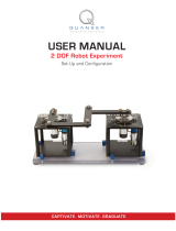 Quanser 2 DOF Planar Robot User manual
-
Miele 59600801D Operating instructions
-
 MK Diamond Products MK-312/412/512 Stone Saws Owner's manual


