Page is loading ...

Models 8751/8754
Pump Style
Soft Serve Freezers
Operating Instructions
056485--M
2/01/02

Complete this page for quick reference when service is required:
Taylor Distributor:
Address:
Phone:
Service:
Parts:
Date of Installation:
Information found on the data label:
Model Number:
Serial Number:
Electrical Specs: Voltage Cycle
Phase
Maximum Fuse Size: A
Minimum Wire Ampacity: A
E February, 2002 Taylor
All rights reserved.
056485--M
Taylor Company
750 N. Blackhawk Blvd.
Rockton, IL 61072
The word Taylor and the Crown design
are registered trademarks in the United States
of America and certain other countries.

Table of Contents Models 8751/8754
Table of Contents
Section 1 To the Installer 1............................................
Water Connections (Water Cooled Units Only) 1............................
Air Cooled Units 1.......................................................
Electrical Connections 1.................................................
Section 2 To the Operator 2...........................................
Compressor Warranty Disclaimer 2.......................................
Section 3 Safety 3....................................................
Section 4 Operator Parts Identification 4...............................
Model 8751 4..........................................................
Model 8754 5..........................................................
Model 8751 Single Spout Door and Beater Assembly 6......................
Model 8754 T hree Spout Door and Beater Assembly 7......................
Air/Mix Pump 8.........................................................
Accessories 9..........................................................
Section 5 Important: To the Operator 10.................................
Symbol Definitions 11....................................................
Power Switch 11.........................................................
Indicator Lights 11.......................................................
MIX REF Key 11.........................................................
STANDBY Key 11........................................................
WASH Key 12...........................................................
AUTO Key 12...........................................................
Pump Key 12............................................................
Reset Button 12.........................................................
Air/Mix Pump Reset Mechanism 12........................................
Adjustable Draw Handle 12...............................................
Feed Tube (Back--up Option) 13...........................................

Models 8751/8754 Table of Contents
Table of Contents -- Page 2
Section 6 Operating Procedures 14.....................................
Assembly 14............................................................
Air/Mix Pump Assembly 18................................................
Sanitizing 21............................................................
Priming 23..............................................................
Closing Procedure 24....................................................
Draining Product From the Freezing Cylinder 25.............................
Rinsing 25..............................................................
Cleaning 25.............................................................
Disassembly 26..........................................................
Brush Cleaning 26.......................................................
Section 7 Important: Operator Checklist 27..............................
During Cleaning and Sanitizing 27.........................................
Troubleshooting Bacterial Count 27........................................
Regular Maintenance Checks 27...........................................
The Air/Mix Pump Checklist 28............................................
Winter Storage 28........................................................
Section 8 Troubleshooting Guide 29....................................
Section 9 Parts Replacement Schedule 33...............................
Section 10 Parts L ist 34.................................................
Wiring Diagrams 44......................................................
Note: Continuin g research results in steady improvements; th erefore, information
in this manual is subject to change without notice.

1
Models 8751/8754 To the Installer
050415
Section 1 To the Installer
This machine is designed for indoor use only.
DO NOT install the machine in an area where
a water jet could be used to clean or rinse the machine.
Failure to follow this instruction may result in serious
electrical shock.
Water Connections
(Water Cooled Units Only)
An adequate cold water supply must be provided with
a hand shut-off valve. On the underside rear of the
base pan, two 3/8” I.P.S. (for single-head units) or two
1/2” I.P.S. (for double-head units) water connections
for inlet and outlet have been provided for easy
hook-up. 1/2” inside diameter water lines should be
connected to the machine. (Flexible lines are
recommended, if local codes permit.) Depending on
local water conditions, it may be advisable to install a
water strainer to prevent foreign substances from
clogging the automatic water valve. There will be only
one water “in” and one water “out” connection for both
single-head and double-head units. DO NOT install a
hand shut-off valve on the water “out” line! Water
should always flow in this order: first, through the
automatic water valve; second, through the
condenser; and third, through the outlet fitting to an
opentrapdrain.
Air Cooled Units
Air cooled units require a minimum of 3” (76 mm) of
clearance around all sides of the freezer to allow for
adequate air flow across the condenser(s). Failure to
allow adequate clearance can reduce the refrigeration
capacity of the freezer and possibly cause permanent
damage to the compressor.
Electrical Connections
Each freezer requires one power supply for each data
label. Check the data label(s) on the freezer for fuse,
circuit ampacity and electrical specifications. Refer to
the wiring diagram provided inside of the electrical box,
for proper power connections.
In the United States, this equipment is intended to be
installed in accordance with the National Electrical
Code (NEC), ANSI/NFPA 70--1987. The purpose of
the NEC code is the practical safeguarding of persons
and property from hazards arising from the use of
electricity. This code contains provisions considered
necessary for safety. Compliance therewith and
proper maintenance will result in an installation
essentially free from hazard!
In all other areas of the world, equipment should be
installed in accordance with the existing local codes.
Please contact your local authorities.
Stationary appliances which are not equipped with a
power cord and a plug or other device to disconnect
the appliance from the power source must have an
all--pole disconnecting device with a contact gap of at
least 3 mm installed in the external installation.
CAUTION: THIS EQUIPMENT MUST BE
PROPERLY GROUNDED! FAILURE TO DO SO
CAN RESULT IN SEVERE PERSONAL INJURY
FROM ELECTRICAL SHOCK!
Beater rotation must be clockwise as viewed looking
into the freezing cylinder of any model freezer.
Note: The following procedures should be
performed by a trained service technician.
To correct rotation on a three-phase unit, interchange
any two incoming power supply lines at freezer main
terminal block only.
To correct rotation on a single-phase unit, change the
leads inside the beater motor. (Follow diagram printed
on motor.)
Electrical connections are made directly to the
terminal block provided in the main control box located
behind the service panel.

2
Models 8751/8754To the Operator
050818
Section 2 To the Operator
The freezer you have purchased has been carefully
engineered and manufactured to give you dependable
operation. The Taylor Company soft-serve models
covered in this manual consist of the 8751 and 8754.
These units, when properly operated and cared for, will
produce a consistent quality product. Like all
mechanical products, they will require cleaning and
maintenance. A minimum amount of care and
attention is necessary if the operating procedures
outlined in this manual are followed closely.
This Operator’s Manual should be read before
operating or performing any maintenance on your
equipment.
Your Taylor freezer will NOT eventually compensate
for and correct any errors during the set-up or filling
operations. Thus, the initial assembly and priming
procedures are of extreme importance. It is strongly
recommended that personnel responsible for the
equipment’s operation, both assembly and
disassembly, go through these procedures together in
order to be properly trained and to make sure that no
confusion exists.
In the event you should require technical assistance,
please contact your local authorized Taylor Distributor.
If the crossed out wheeled bin symbol is
affixed to this product, it signifies that this product is
compliant with the EU Directive as well as other similar
legislation in effect after August 13, 2005. Therefore,
it must be collected separately after its use is
completed, and cannot be disposed as unsorted
municipal waste.
The user is responsible for returning the product to the
appropriate collection facility, as specified by your local
code.
For additional information regarding applicable local
laws, please contact the municipal facility and/or local
distributor.
Compressor Warranty Disclaimer
The refrigeration compressor(s) on this machine are
warranted for the term indicated on the warranty card
accompanying this machine. However , due to the
Montreal Protocol and the U.S. Clean Air Act
Amendments of 1990, many new refrigerants are
being tested and developed, thus seeking their way
into the service industry. Some of these new
refrigerants are being advertised as drop-in
replacements for numerous applications. It should be
noted that, in the event of ordinary service to this
machine’s refrigeration system, only the refrigerant
specified on the affixed data label should be used.
The unauthorized use of alternate refrigerants will void
your compressor warranty. It will be the owner’s
responsibility to make this fact known to any technician
he employs.
It should also be noted that Taylor does not warrant the
refrigerant used in its equipment. For example, if the
refrigerant is lost during the course of ordinary service
to this machine, Taylor has no obligation to either
supply or provide its replacement either at billable or
unbillable terms. Taylor does have the obligation to
recommend a suitable replacement if the original
refrigerant is banned, obsoleted, or no longer available
during the five year warranty of the compressor .
The Taylor Company will continue to monitor the
industry and test new alternates as they are being
developed. Should a new alternate prove, through our
testing, that it would be accepted as a drop-in
replacement, then the above disclaimer would
become null and void. To find out the current status of
an alternate refrigerant as it relates to your
compressor warranty, call the local Taylor Distributor
or the Taylor Factory. Be prepared to provide the
Model/Serial Number of the unit in question.

3
Models 8751/8754 Safety
050415
Section 3 Safety
We at Taylor Company are concerned about the safety
of the operator when he or she comes in contact with
the freezer and its parts. Taylor has gone to extreme
efforts to design and manufacture built-in safety
features to protect both you and the service technician.
As an example, warning labels have been attached to
the freezer to further point out safety precautions to the
operator.
IMPORTANT -- Failure to adhere to the
following safety precautions may result in severe
personal injury. Failure to comply with these
warnings may also damage the machine and its
components. Component damage will result in
part replacement expense and service repair
expense.
To Operate Safely:
DO NOT operate the freezer without reading
this operator’s manual. Failure to follow this instruction
may result in equipment damage, poor freezer
performance, health hazards, or personal injury.
S DO NOT operate the freezer unless it is
properly grounded.
S DO NOT attempt any repairs unless the
main power supply to the freezer has been
disconnected.
S DO NOT operate the freezer with larger
fuses than specified on the freezer data
label.
Failure to follow these instructions may result in
electrocution or damage to the machine. Contact your
local authorized Taylor Distributor for service.
DO NOT use a water jet to clean or rinse the
freezer. Failure to follow this instruction may result in
serious electrical shock.
S DO NOT allow untrained personnel to
operate this machine.
S DO NOT operate the freezer unless all
service panels and access doors are
restrained with screws.
S DO NOT remove the door, beater and
blades, drive shaft, or air/mix pump unless
all control switches are in the OFF position.
S DO NOT put objects or fingers in door
spout.
Failure to follow these instructions may result in
contaminated product or severe personal injury to
fingers or hands from hazardous moving parts.
USE EXTREME CAUTION when removing
the beater assembly. The scraper blades are very
sharp and may cause injury.
This freezer must be placed on a level
surface. Failure to comply may result in personal injury
or equipment damage.
DO NOT obstruct air intake and discharge openings.
The minimum required air space on all sides is 3”
(76 mm). Failure to follow this instruction may cause
poor freezer performance and damage to the
machine.
This freezer is designed to operate indoors, under
normal ambient temperatures of 70_-- 7 5 _F
(21_-- 2 4 _C). The freezer has successfully performed
in high ambient temperatures of 104_F(40_C) at
reduced capacities.
NOISE LEVEL: Airborne noise emission does not
exceed 78 dB(A) when measured at a distance of 1.0
meter from the surface of the machine and at a height
of 1.6 meters from the floor.

4
Models 8751/8754Operator Parts Identification
Section 4 Operator Parts Identification
Model 8751
ITEM DESCRIPTION PART NO.
1 COVER A. -HOPPER X38458
2 GASKET -HOPPER COVER 038375
3 LOUVER-SIDE 017471
4 PANEL·A.-FRONT X33237
5 STUD-NOSE CONE 022822
6 PANEL -UPPER SIDE 024426
7 PANEL A. -SIDE -LOWER-LOUV X39075
8 SHIELD-SPLASH 022763
9 TRAY-DRIP147/8X51/8 013690
ITEM DESCRIPTION PART NO.
10 PANEL -SERVICE 047170
11 CASTER-SWV 018794
12 ADAPTOR·A.-CASTER X18915
13 PANEL- REAR 048203
14 PANEL A.-LOWER SIDE X24424
15 PAN - DRIP 11 5/8 LONG 027503
16 PANEL-UPPER SIDE RIGHT 028823
17 PAN-DRIP *PUMP 048435

5
Models 8751/8754 Operator Parts Identification
Model 8754
ITEM DESCRIPTION PART NO.
1 COVER A. -HOPPER X38458
2 GASKET -HOPPER COVER 038375
3 PAN-DRIP 1 7-1/4”LONG 027504
4 PANEL -UPPER SIDE L 028822
5 STUD-NOSE CONE 022822
6 PANEL A. -FRONT X32956
7 PANEL A. -SIDE *LOWER L X46447
8 SHIELD-SPLASH 022766
ITEM DESCRIPTION PART NO.
9 TRAY-DRIP 014533
10 PANEL- SERVICE 046584
11 CASTER-SWV 018794
12 ADAPTOR A.-CASTER X18915
13 PANEL A.-SIDE -LOWER R X46448
14 PANEL-UPPER SIDE RIGHT 028823
15 LOUVER-SIDE 017471
16 PANEL- REAR 053782

6
Models 8751/8754Operator Parts Identification
Model 8751 Single Spout Door and Beater Assembly
ITEM DESCRIPTION PART NO.
1 HANDLE A. -DRAW-ADJ. X55096
1a HANDLE-ADJUSTABLE 028804
1b SCREW-ADJUSTMENT 055092
1c O-RING-1/4 OD X .070W 50 015872
1d NUT -JAM 029639-BLK
2 NUT -STUD 021508
3 DOOR A. -1 SPOUT *VALOX* X51531-10
4 VALVE A. -DRAW X18303
5 O-RING-7/8 OD X .103W 014402
6 CAP-DESIGN -1.010”ID -6 POINT 014218
7 O-RING-5/16 OD X .070W 016272
8 PLUG-PRIME 028805
ITEM DESCRIPTION PART NO.
9 O-RING-3/8 OD X .070W 016137
10 PIN A.-PIVOT X22820
11 GASKET-DOOR HT 4”-DOUBLE 048926
12 BEARING-FRONT-SHOE 050348
13 SHOE-FRONT HELIX *FRONT* 050347
14 SHOE-FRONT HELIX *REAR* 050346
15 BEATER A.-3.4QT-1 PIN X46231
16 CLIP-SCRAPER·BLADE*7” 046236
17 BLADE-SCRAPER-PLAS. 8 -1/8 046235
18 SHAFT-BEATER 032564
19 SEAL-DRIVE SHAFT 032560

7
Models 8751/8754 Operator Parts Identification
Model 8754 Three Spout Door and Beater Assembly
ITEM DESCRIPTION PART NO.
1 HANDLE A. - DRAW X55096
1a DRAW HANDLE 028804
1b SCREW-ADJUST 055092
1c O-RING 1/4OD X .070W 015872
1d NUT -JAM 029639-BLK
2 NUT -STUD FLAT LONG 034382
3 NUT -STUD FLAT SHORT 034383
4 VALVE A. - DRAW X18303
5 O-RING 7/8OD X .070W 014402
6 SHAFT -BEATER 032564
7 SEAL -DRIVE SHAFT 032560
8 CAP-DESIGN 014218
ITEM DESCRIPTION PART NO.
9 DECAL -DOOR 021521
10 DOOR A.- 3 -SPOUT X51532-12
11 ROD A.- PIVOT X20683
12 O-RING 5/16OD X .070W 016272
13 GASKET-DOOR HT 4” 048926
14a BEARING-FRONT 050348
14b SHOE-FRONT HELIX *REAR* 050346
14c SHOE-FRONT HELIX *FRONT* 050347
15 BEATER A.-3.4QT-1 PIN X46231
16 BLADE-SCRAPER-PLASTIC 046235
17 CLIP-SCRAPER·BLADE*7.00·IN 046236

8
Models 8751/8754Operator Parts Identification
Air/Mix Pump
ITEM DESCRIPTION PART NO.
1 TUBE A. --MIX INLET--HOPPER X45318
2 SEAL --AIR INLET FITTING 045327
3 SPRING--TAPERED 1 --7/8 022456
4 POPPET --RUBBER BLACK 022473
5 BODY A. --COAX VALVE X46860-B
6 O--RING 2-1/8 OD X .139 W 020051
7 O--RING 1-3/8 OD X .103 W 018664
8 PISTON --COAX PUMP 045319-B
9 PINA.--COAXPUMPHTSS X36950
10 CLIP--MIX PUMP RETAINER 044641
11 RING--CHECK 2” OD X 1/2 020050
12 SHAFT A.--DRIVE MIX PUMP X39084
ITEM DESCRIPTION PART NO.
12a O--RING 1/2 ID X .139 W--206 048632
12b O--RING 1-3/4 OD X .139 W 008904
13 RING--CHECK 1-1/4 OD X 3/8 033215
14 CYLINDER A. --PUMP HT X44755
15 O--RING 11/16 OD X .103 W--RED 016132
16 PIN--COTTER HAIRPIN 1/8 DIA. 044731
TUBE A. --FEED--HPR PUMP SS L
(8754)
X44662
17
TUBE A. --FEED--HPR PUMP SS R
(8754)
X44664
TUBE A. --HT PUMP FEED SS
(8751)
X44666
18 O--RING 3/4 OD X .103 W 015835

9
Models 8751/8754 Operator Parts Identification
Accessories
ITEM DESCRIPTION PART NO.
1 BRUSH--MIX PUMP BODY 023316
2 BRUSH--DOUBLE ENDED 013072
3 BRUSH--REAR BEARING 013071
4 BRUSH--DRAW VALVE 013073
5 LUBRICANT--TAYLOR 4 OZ. 047518
ITEM DESCRIPTION PART NO.
6 SANITIZER --KAY 5 (125 PKTS) 041082
7 PAIL-- MIX 10 QT. 013163
8
KIT A.--TUNE UP (MODEL 8751) X49463--9
8
KIT A.--TUNE UP (MODEL 8754) X49463--19

10
Models 8751/8754Important: To the Operator
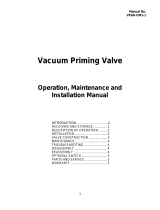
Section 5 Important: To the Operator
8751
8754
ITEM DESCRIPTION
1 MIX LOW INDICATOR LIGHT
2 MIX REFRIGERATION KEY
3 STANDBY KEY
4 WASH KEY
5 AUTO KEY
ITEM DESCRIPTION
6 PUMP KEY
7 POWER ON/OFF (TOGGLE)
8 RESET BUTTON -- BEATER MOTOR
9 RESET BUTTON -- PUMP

11
Models 8751/8754 Important: T o the Operator
Symbol Definitions
To better communicate in the International arena,
symbols have replaced words on many of our operator
switches, function, and fault indicators. Your Taylor
equipment is designed with these International
symbols.
The following chart identifies the symbol definitions.
=OFF
=ON
=MIX
= STANDBY
= WASH
=AUTO
=PUMP
Power Switch
When placed in the ON position, the power switch
allows SOFTECH control panel operation.
Indicator Lights
Located on the front of the machine is a mix level
indicating light. When the light begins to flash, it
indicates that the mix hopper has a low supply of mix
and should be refilled as soon as possible. Always
maintain at least 3” (76 mm) of mix in the hopper. If you
neglect to add mix, a freeze-up may occur. This will
cause eventual damage to the beater, blades, drive
shaft, and freezer door.
MIX REF Key
When the MIX REF key is pressed, the light comes on
indicating the mix hopper refrigeration system is
operating. For the Model 8754 the MIX REF is
controlled by the left side of the freezer as viewed from
the operator end. The MIX REF function cannot be
cancelled unless the AUTO or STANDBY modes are
cancelled first.
STANDBY Key
The Separate Hopper Refrigeration System (SHR)
and the Cylinder Temperature Retention System
(CTR) are standard features. The SHR incorporates
the use of a separate small refrigeration system to
maintain the mix in the hopper below 40_(4.4_C) to
assure bacteria control. The CTR works with the SHR
to maintain a good quality product. During long “No
Sale” periods, it is necessary to warm the product in
the freezing cylinder to approximately 35_Fto40_F
(1.7_Cto4.4_C) to prevent overbeating and product
breakdown.
To activate the SHR and CTR, press the STANDBY
key. Remove the air orifice and place the air tube (end
without the hole) into the mix inlet hole.
When the ST ANDBY key is pressed, the light comes
on, indicating the CTR (Cylinder Temperature
Retention System) has been activated. In the
STANDBY mode, the WASH and AUTO functions are
automatically cancelled. The MIX REF function is
automatically locked in to maintain the mix in the
hopper.
To resume normal operation, press the AUTO key.
When the unit cycles off, the product in the freezing
cylinder will be at serving viscosity. At this time, place
the air tube (end with the hole) into the mix inlet hole
and install the air orifice.

12
Models 8751/8754Important: To the Operator
WASH Key
When the WASH key is pressed, the light comes on.
This indicates beater motor operation. The STANDBY
or AUTO modes must be cancelled first to activate the
W ASH mode.
AUTO Key
When the AUTO key is pressed, the light comes on.
This indicates that the main refrigeration system has
been activated. In the AUTO mode, the W ASH or
STANDBY functions are automatically cancelled. The
MIX REF function is automatically locked in to
maintain the mix in the mix hopper.
Note: An indicating light and an audible tone will
sound whenever a mode of operation has been
pressed. To cancel any function, press the key again.
The light and mode of operation will shut off.
Pump Key
When the PUMP key is pressed, the light comes on,
indicating the air/mix pump will operate as required.
Reset Button
The reset button is located in the service panel on the
front of the machine. The reset protects the beater
motor from an overload condition. If an overload
occurs, the reset mechanism will trip. To properly reset
the freezer, press the AUTO key to cancel the cycle.
T urn the power switch to the OFF position. Press the
reset butt on firmly.
Do not use metal objects to press the reset
button. Failure to follow this instruction may
result in electrocution.
T urn the power switch to the ON position. Press the
W ASH key and observe the freezer’s performance.
Open the side access panel. Make sure the beater
motor is turning the drive shaft in a clockwise direction
(from the operator end) without binding.
If the beater motor is turning properly, press the WASH
key to cancel the cycle. Press the AUTO key to resume
normal operation. If the freezer shuts down again,
contact a service technician. (For the Model 8754
press the AUTO key on both sides of the unit to resume
normal operation.)
Air/Mix Pump Reset Mechanism
The reset button for the pump is located in the service
panel. The reset protects the pump from an overload
condition. Should an overload occur, the reset
mechanism will trip. To reset the pump, press the reset
button firmly.
Adjustable Draw Handle
These units feature an adjustable draw handle to
provide the best portion control. The draw handle
should be adjusted to provide a flow rate of 5 to 7-1/2
oz. (148 to 222 ml) of product per 10 seconds. To
INCREASE the flow rate, turn the screw
COUNTERCLOCKWISE. Turn the screw
CLOCKWISE to DECREASE the flow rate. During
“Sanitizing” and “Rinsing”, the flow rate can be
increased by removing the pivot pin and placing the
restrictive bar on the TOP. When drawing product,
always place the restrictive bar on the bottom.
Figure 1
IMPORTANT: Once the draw rate is set, tighten the
lock nut with a wrench.

13
Models 8751/8754 Important: T o the Operator
050201
Feed Tube (Back--up Option)
If the air/mix pump has become inoperable because of
a missing or damaged part, the operator can
temporarily operate the unit using the feed tube. The
product ejection rate will be slower when the feed tube
is used instead of the air/mix pump.
Figure 2
ITEM DESCRIPTION PART NO.
1 ORIFICE 022465--100
2 O-- RING-- 3/8 OD X .070 W 016137
3 TUBE A. --FEED--SS 5/32 HOLE X29429--2
4 O--RING--.643 OD X .077 W 018572
The feed tube serves two purposes. One end of the
tube has a hole and the other end does not.
1. Normal Operation
During normal operation, the end of the feed tube
with the hole is placed into the mix inlet hole.
Every time the draw handle is raised, new mix and
air from the hopper flow into the freezing cylinder.
This keeps the freezing cylinder properly loaded
and maintains overrun.
2. Long “No Sale” Periods
During long “No Sale” periods, the unit can be
placed into the Standby mode. This maintains
product temperatures below 40_F(4.4_C) in both
the hopper and the freezing cylinder , and helps
prevent overbeating and product breakdown.
To place the unit into the Standby mode, press the
STANDBY key. Remove the air orifice. Lubricate
the o--rings located on the end of the feed tube
without the hole. Place that end of the tube into
the mix inlet hole.This will prevent any mix from
entering the freezing cylinder.
Note: The air orifice is used to meter a certain
amount of air into the freezing cylinder. The air
orifice maintains overrun and allows enough mix
to enter the freezing cylinder after a draw.

14
Models 8751/8754Operating Procedures
050201
Section 6 Operating Procedures
The Model 8751 has been selected to illustrate the
step-by-step operating procedures for both models
contained in this manual. These models, for all
practical purposes of operation, are the same.
Each unit stores mix in a hopper. The mix is pumped
into the freezing cylinder. They have 3.4 quart (3.2
liter) capacity freezing cylinders and 20 quart (18.9
liter) mix hoppers.
Duplicate the following procedures, where they apply,
for the second freezing cylinder on the Model 8754.
We begin our instructions at the point where we enter
the store in the morning and find the parts
disassembled and laid out to air dry from the previous
night’s cleaning.
These opening procedures will show you how to
assemble these parts into the freezer, sanitize them,
and prime the freezer with fresh mix in preparation to
serve your first portion.
If you are disassembling t he machine for the first time
or need information to get to this starting point in our
instructions, turn to page 26, “Disassembly”, and start
there.
Assembly
Note: When lubricating parts, use an approved food
grade lubricant (example: Taylor Lube).
MAKE SURE POWER SWITCH IS IN THE
“OFF ” POSITION! Failure to follow this instruction
may result in severe personal injury from hazardous
moving parts.
Step 1
Install the drive shaft. Lubricate the groove and shaft
portion that comes in contact with the bearing on the
beater drive shaft. Slide the seal over the shaft and
groove until it snaps into place. DO NOT lubricate the
hex end of the drive shaft.
Fill the inside portion of the seal with 1/4” more
lubricant and lubricate the flat side of the seal that fits
onto the rear shell bearing.
Figure 3
Insert the drive shaft into the freezing cylinder, hex end
first, and into the rear shell bearing until the seal fits
securely over the rear shell bearing. Engage the hex
end firmly into the drive coupling. Be sure the drive
shaft fits into the drive coupling without binding.
Figure 4

15
Models 8751/8754 Operating Procedures
Step 2
Install the beater assembly. First check the scraper
blades for any nicks or signs of wear. If any nicks are
present, or if the blades are worn, replace both blades.
If the blades are in good condition, install the scraper
blade clips on the scraper blades. Place the rear
scraper blade over the rear holding pin on the beater .
Note: The hole on the scraper blade must fit securely
over the pin to prevent costly damage.
Figure 5
Holding the rear blade on the beater, slide it halfway
into the freezing cylinder. Install the front scraper blade
over the front holding pin.
Install the beater shoes.
Figure 6
Slide the beater assembly the rest of the way into the
freezing cylinder.
Make sure the beater assembly is in position over the
drive shaft. Turn the beater slightly to be certain that
the beater is properly seated. When in position, the
beater will not protrude beyond the front of the freezing
cylinder.
Repeat steps 1 and 2 for the other side of the freezer
on the Model 8754.
Step 3
Assemble the freezer door. Place the large rubber
gasket(s) into the groove(s) on the back side of the
freezer door .
Slide the white plastic front bearing(s) over the baffle
rod(s) onto the bearing hub(s) making certain that the
flanged end of the bearing is resting against the freezer
door. DO NOT LUBRICATE THE GASKET(S) OR
THE FRONT BEARING(S).
Figure 7
Note: There are two gaskets and two front bearings
for the Model 8754 door, one for each freezing cylinder.
Figure 8

16
Models 8751/8754Operating Procedures
Slide the two o-rings into the grooves on the prime
plug(s). Apply an even coat of Taylor Lube to the
o-rings and shaft(s).
Figure 9
Note: There are two prime plugs for the Model 8754
door, one for each freezing cylinder.
Insert the prime plug(s) into the hole(s) in the top of the
freezer door , and push down.
Figure 10
Step 4
Install the freezer door. Insert the baffle rod(s)
through the opening in the beater(s) and seat the door
flush with the freezing cylinder. With the door seated
on the freezer studs, install the handscrews. T ighten
equally in a crisscross pattern to insure the door is
snug.
Note: On the Model 8754, the short handscrews go
on the bottom and the long handscrews go on the top.
Figure 11
Step 5
Install the draw valve(s). Slide the two o-rings into
the grooves on the draw valve(s), and lubricate.
Figure 12
Note: The Model 8754 has three draw valves.
Lubricate the inside of the freezer door spout(s), top
and bottom, and insert the draw valve(s) from the
bottom until the slot in the draw valve(s) comes into
view.
Figure 13
/