Page is loading ...

H
S 5
Installation instructions
Englis h
Date: 08-2012
Document numbe r: 87146-2-EN
© 2012 Raymarine UK Limite d
HS5


Trademarkandpatentsnotice
Autohelm,hsb
2
,RayTechNavigator,SailPilot,SeaTalk,SeaTalk
NG
,SeaTalk
HS
andSportpilotareregisteredtrademarksofRaymarine
UKLimited.RayTalk,Seahawk,Smartpilot,PathnderandRaymarineareregisteredtrademarksofRaymarineHoldingsLimited.
FLIRisaregisteredtrademarkofFLIRSystems,Inc.and/oritssubsidiaries.
Allothertrademarks,tradenames,orcompanynamesreferencedhereinareusedforidenticationonlyandarethepropertyof
theirrespectiveowners.
Thisproductisprotectedbypatents,designpatents,patentspending,ordesignpatentspending.
FairUseStatement
Youmayprintnomorethanthreecopiesofthismanualforyourownuse.Youmaynotmakeanyfurthercopiesordistributeorusethe
manualinanyotherwayincludingwithoutlimitationexploitingthemanualcommerciallyorgivingorsellingcopiestothirdparties.
Producthandbooks
ThelatestversionsofallEnglishandtranslatedhandbooksareavailabletodownloadinPDFformatfromthewebsitewww.raymarine.com.
Pleasecheckthewebsitetoensureyouhavethelatesthandbooks.
Copyright©2012RaymarineUKLtd.Allrightsreserved.
ENGLISH
Documentnumber:87146-2
Date:08-2012


Contents
Chapter1Introduction.............................................7
Handbookinformation.....................................................7
Productoverview............................................................7
Safetynotices.................................................................7
Importantinformation......................................................7
Chapter2Planningtheinstallation........................9
2.1Installationchecklist..................................................10
2.2Partssupplied...........................................................10
2.3SeaT alk
hs
..................................................................11
2.4Typicalsystems........................................................11
2.5Multipleswitches.......................................................12
Chapter3Cablesandconnections.........................13
3.1Generalcablingguidance..........................................14
3.2Connectionsoverview...............................................14
3.3Networkhardware.....................................................15
3.4RayNetconnectornetworkcables..............................15
3.5Networkcableconnectortypes..................................16
3.6Equipmentconnection...............................................16
3.7Powerconnection.....................................................17
Chapter4Installation...............................................19
4.1Locationrequirements...............................................20
4.2Mountingtheunit......................................................20
Chapter5Troubleshootingandsupport................21
5.1LEDlocations...........................................................22
5.2LEDindications.........................................................23
5.3Networkswitchtroubleshooting..................................24
5.4Raymarinecustomersupport.....................................25
AppendixATechnicalspecication.......................27
5

6HS5

Chapter1:Introduction
Handbookinformation
ThishandbookdescribeshowtoinstalltheRaymarineHS5network
switchaspartofamarineelectronicsinstallation.
Thishandbookincludesinformationtohelpyou:
•planyourinstallation;
•installandconnecttheproductasapartofyoursystemof
Raymarineelectronics;
•conductcheckstoensurethattheproducthasbeeninstalled
correctly;
•obtainsupportifrequired.
ThisandotherRaymarineproductdocumentationisavailableto
downloadinPDFformatfromwww.raymarine.com.
Productoverview
ARaymarinenetworkswitchenablesyoutoconnectmultiple
SeaTalk
hs
devicestoaRaymarinemultifunctiondisplay.
Raymarinenetworkstypicallyconsistofatleast2ofthefollowing
SeaTalk
hs
devices:
•Radarscanner.
•DigitalSounderModule(DSM).
•Thermalcamera.
•Additionalmultifunctiondisplay.
Safetynotices
Warning:Productinstallationand
operation
Thisproductmustbeinstalledandoperatedin
accordancewiththeinstructionsprovided.Failureto
dosocouldresultinpersonalinjury,damagetoyour
vesseland/orpoorproductperformance.
Warning:Switchoffpowersupply
Ensurethevessel’spowersupplyisswitchedOFF
beforestartingtoinstallthisproduct.DoNOTconnect
ordisconnectequipmentwiththepowerswitchedon,
unlessinstructedinthisdocument.
Warning:Potentialignitionsource
ThisproductisNOTapprovedforusein
hazardous/ammableatmospheres.DoNOTinstallin
ahazardous/ammableatmosphere(suchasinan
engineroomornearfueltanks).
Warning:Productgrounding
Beforeapplyingpowertothisproduct,ensureithas
beencorrectlygrounded,inaccordancewiththe
instructionsinthisguide.
Importantinformation
Caution:Powersupplyprotection
Wheninstallingthisproductensurethepowersource
isadequatelyprotectedbymeansofasuitably-rated
fuseorautomaticcircuitbreaker.
Caution:Serviceandmaintenance
Thisproductcontainsnouserserviceable
components.Pleasereferallmaintenanceandrepair
toauthorizedRaymarinedealers.Unauthorizedrepair
mayaffectyourwarranty.
Wateringress
Wateringressdisclaimer
Althoughthewaterproofratingcapacityofthisproductmeetsthe
IPX6standard,waterintrusionandsubsequentequipmentfailure
mayoccuriftheproductissubjectedtocommercialhigh-pressure
washing.Raymarinewillnotwarrantproductssubjectedto
high-pressurewashing.
IMOandSOLAS
Theequipmentdescribedwithinthisdocumentisintendedforuse
onleisuremarineboatsandworkboatsnotcoveredbyInternational
MaritimeOrganization(IMO)andSafetyofLifeatSea(SOLAS)
CarriageRegulations.
Productdisposal
DisposeofthisproductinaccordancewiththeWEEEDirective.
TheWasteElectricalandElectronicEquipment(WEEE)
Directiverequirestherecyclingofwasteelectricalandelectronic
equipment.WhilsttheWEEEDirectivedoesnotapplytosome
Raymarineproducts,wesupportitspolicyandaskyoutobeaware
ofhowtodisposeofthisproduct.
Technicalaccuracy
Tothebestofourknowledge,theinformationinthisdocument
wascorrectatthetimeitwasproduced.However,Raymarine
cannotacceptliabilityforanyinaccuraciesoromissionsitmay
contain.Inaddition,ourpolicyofcontinuousproductimprovement
maychangespecicationswithoutnotice.Asaresult,Raymarine
cannotacceptliabilityforanydifferencesbetweentheproduct
andthisdocument.PleasechecktheRaymarinewebsite
(www.raymarine.com)toensureyouhavethemostup-to-date
version(s)ofthedocumentationforyourproduct.
EMCinstallationguidelines
Raymarineequipmentandaccessoriesconformtotheappropriate
ElectromagneticCompatibility(EMC)regulations,tominimize
electromagneticinterferencebetweenequipmentandminimizethe
effectsuchinterferencecouldhaveontheperformanceofyour
system
CorrectinstallationisrequiredtoensurethatEMCperformanceis
notcompromised.
ForoptimumEMCperformancewerecommendthatwherever
possible:
•Raymarineequipmentandcablesconnectedtoitare:
–Atleast1m(3ft)fromanyequipmenttransmittingorcables
carryingradiosignalse.g.VHFradios,cablesandantennas.
InthecaseofSSBradios,thedistanceshouldbeincreased
to7ft(2m).
–Morethan2m(7ft)fromthepathofaradarbeam.Aradar
beamcannormallybeassumedtospread20degreesabove
andbelowtheradiatingelement.
•Theproductissuppliedfromaseparatebatteryfromthatused
forenginestart.Thisisimportanttopreventerraticbehavior
anddatalosswhichcanoccuriftheenginestartdoesnothave
aseparatebattery.
•Raymarinespeciedcablesareused.
•Cablesarenotcutorextended,unlessdoingsoisdetailedin
theinstallationmanual.
Introduction
7

Note:Whereconstraintsontheinstallationpreventanyof
theaboverecommendations,alwaysensurethemaximum
possibleseparationbetweendifferentitemsofelectrical
equipment,toprovidethebestconditionsforEMCperformance
throughouttheinstallation
Suppressionferrites
Raymarinecablesmaybettedwithsuppressionferrites.These
areimportantforcorrectEMCperformance.Ifaferritehastobe
removedforanypurpose(e.g.installationormaintenance),itmust
bereplacedintheoriginalpositionbeforetheproductisused.
Useonlyferritesofthecorrecttype,suppliedbyRaymarine
authorizeddealers.
Connectionstootherequipment
Requirementforferritesonnon-Raymarinecables
IfyourRaymarineequipmentistobeconnectedtootherequipment
usingacablenotsuppliedbyRaymarine,asuppressionferrite
MUSTalwaysbeattachedtothecableneartheRaymarineunit.
Declarationofconformity
RaymarineUKLtd.declaresthatthisproductiscompliantwiththe
essentialrequirementsofEMCdirective2004/108/EC.
TheoriginalDeclarationofConformitycerticatemaybeviewedon
therelevantproductpageatwww.raymarine.com.
Warrantyregistration
ToregisteryourRaymarineproductownership,pleasevisit
www.raymarine.comandregisteronline.
Itisimportantthatyouregisteryourproducttoreceivefullwarranty
benets.Yourunitpackageincludesabarcodelabelindicatingthe
serialnumberoftheunit.Youwillneedthisserialnumberwhen
registeringyourproductonline.Youshouldretainthelabelforfuture
reference.
8HS5

2.1Installationchecklist
Installationincludesthefollowingactivities:
InstallationTask
1Planyoursystem.
2
Obtainallrequiredequipmentandtools.
3
Siteallequipment.
4Routeallcables.
5
Drillcableandmountingholes.
6Makeallconnectionsintoequipment.
7
Secureallequipmentinplace.
8Poweronandtestthesystem.
Schematicdiagram
Aschematicdiagramisanessentialpartofplanninganyinstallation.
Itisalsousefulforanyfutureadditionsormaintenanceofthe
system.Thediagramshouldinclude:
•Locationofallcomponents.
•Connectors,cabletypes,routesandlengths.
2.2Partssupplied
D12 3 1 2 -1
2
4
1
3
1.Networkswitch.
2.Fixingscrews.
3.Powercable(redandblack).
4.Documentationpack,consistingof:
•Installationinstructions.
•Mountingtemplate.
•Warrantypolicy.
10HS5

2.3SeaTalk
hs
SeaTalk
hs
isanethernetbasedmarinenetwork.Thishighspeed
protocolallowscompatibleequipmenttocommunicaterapidlyand
sharelargeamountsofdata.
InformationsharedusingtheSeaT alk
hs
networkincludes:
•Sharedcartography(betweencompatibledisplays).
•Digitalradardata.
•Sonardata.
2.4Typicalsystems
Example:Basicsystem
D12 3 2 1 -2
SeaTalk
hs
/ RayNet
SeaTalk
hs
/ RayNet
3
21
4
1.Networkswitch.
2.Multifunctiondisplay.
3.Radarscanner.
4.Thermalcamera.
Example:Expandedsystem
D12 5 8 2 -1
SeaTalk
hs
/ RayNet
SeaTalk
hs
/ RayNet
3
3
2
5
SeaTalk
hs
/ RayNet
8
2
6
7
1
4
1.Thermalcamera.
2.Multifunctiondisplay.
3.Networkswitch.
4.Connectionbetween2networkswitches(Port5mustbeused
for1000Mbit/Soperation).
5.Radarscanner.
6.AntennaforSiriusweatherreceiver.
7.Siriusweatherreceiver.
8.DigitalSounderModule(DSM).
Planningtheinstallation
11

2.5Multipleswitches
Systemswithmorethan5SeaTalk
hs
devicesrequiremorethan
onenetworkswitch.Networkswitchescanbeconnectedtogether
(“daisy-chaining”)forthispurpose.
Thenetworkswitchprovidesadedicatedhigh-speed(1000Mbit/S)
portforconnectingswitchestogetherwhilestillretainingfulldata
bandwidththroughoutthesystem.However,eachswitchonly
hasonehigh-speedport(port5),soyoucanonlyconnectupto
2switchesusingthehigh-speed(1000Mbit/S)connection.Any
additionalnetworkswitchesmustbeconnectedtogetherusinga
standardspeed(100Mbit/S)port(ports1to4).
Youshouldtakethisfactorintoaccountwhenplanningyoursystem.
ThemaximumnumberofSeaT alk
hs
devicesthatcanbeconnected
inanysinglesystemis25.
Thefollowingdiagramillustrates2networkswitchesconnected
togetherusingthehigh-speed(1000Mbit/S)connection(port5):
D12 3 2 2 -1
12
HS5

3.1Generalcablingguidance
Cabletypesandlength
Itisimportanttousecablesoftheappropriatetypeandlength
•Unlessotherwisestateduseonlystandardcablesofthecorrect
type,suppliedbyRaymarine.
•Ensurethatanynon-Raymarinecablesareofthecorrectquality
andgauge.Forexample,longerpowercablerunsmayrequire
largerwiregaugestominimizevoltagedropalongtherun.
Routingcables
Cablesmustberoutedcorrectly,tomaximizeperformanceand
prolongcablelife.
•DoNOTbendcablesexcessively.Whereverpossible,ensurea
minimumbenddiameterof200mm(8in)/minimumbendradius
of100mm(4in).
100 mm (4 in)
200 mm (8 in)
•Protectallcablesfromphysicaldamageandexposuretoheat.
Usetrunkingorconduitwherepossible.DoNOTruncables
throughbilgesordoorways,orclosetomovingorhotobjects.
•Securecablesinplaceusingtie-wrapsorlacingtwine.Coilany
extracableandtieitoutoftheway.
•Whereacablepassesthroughanexposedbulkheadordeckhead,
useasuitablewatertightfeed-through.
•DoNOTruncablesneartoenginesoruorescentlights.
Alwaysroutedatacablesasfarawayaspossiblefrom:
•otherequipmentandcables,
•highcurrentcarryingacanddcpowerlines,
•antennae.
Strainrelief
Ensureadequatestrainreliefisprovided.Protectconnectorsfrom
strainandensuretheywillnotpulloutunderextremeseaconditions.
Circuitisolation
Appropriatecircuitisolationisrequiredforinstallationsusingboth
ACandDCcurrent:
•Alwaysuseisolatingtransformersoraseparatepower-inverter
torunPC’s,processors,displaysandothersensitiveelectronic
instrumentsordevices.
•AlwaysuseanisolatingtransformerwithWeatherFAXaudio
cables.
•Alwaysuseanisolatedpowersupplywhenusinga3rdparty
audioamplier.
•AlwaysuseanRS232/NMEAconverterwithopticalisolationon
thesignallines.
•AlwaysmakesurethatPC’sorothersensitiveelectronicdevices
haveadedicatedpowercircuit.
Cableshielding
Ensurethatalldatacablesareproperlyshieldedthatthecable
shieldingisintact(e.g.hasn’tbeenscrapedoffbybeingsqueezed
throughatightarea).
3.2Connectionsoverview
1 2 3
4
5 6
D12 3 1 3 -1
1.Power(12V/24V).
2.Port1(10or100Mbit/S).
3.Port2(10or100Mbit/S).
4.Port3(10or100Mbit/S).
5.Port4(10or100Mbit/S).
6.Port5(10,100,or1000Mbit/S).
Note:Theprotectivecapsshouldbettedtoanyunusedports.
14
HS5

3.3Networkhardware
ItemPartnumberNotes
HS5SeaTalk
hs
network
switch
A80007
5–portswitchfor
networkconnection
ofmultipleSeaTalk
hs
devicesfeaturing
RayNetconnectors.
Equipmentwith
SeaTalk
hs
connectors
canalsobeconnected
viasuitableadaptor
cables.
SeaTalk
hs
network
switch
E55058
8–portswitchfornetwork
connectionofmultiple
SeaTalk
hs
devices.
SeaTalk
hs
crossover
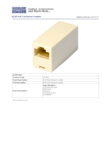
coupler
E55060Enablesdirect
connectionofSeaTalk
hs
devicestosmaller
systemswhereaswitch
isnotrequired.Also
enablestheconnection
ofSeaTalk
hs
devices
toanHS5SeaTalk
hs
networkswitch(in
conjunctionwitha
RayNettoRJ45cable).
3.4RayNetconnectornetworkcables
CablePartnumber
1m(3.28ft)RayNettoSeaTalk
hs
(RJ45)cable
A62360
2m(6.56ft)RayNettoRayNetcable
A62361
5m(16.4ft)RayNettoRayNetcable
A80005
10m(32.8ft)RayNettoRayNetcable
A62362
20m(65.6ft)RayNettoRayNetcable
A80006
RayNetcablepuller5packR70014
Cablesandconnections15

3.5Networkcableconnectortypes
Thereare2typesofnetworkcableconnector—SeaTalk
hs
and
RayNet.
SeaTalk
hs
connector.
RayNetconnector.
3.6Equipmentconnection
SeaTalk
hs
equipmentisconnectedtotheswitchusingRayNet
cablesoracombinationofSeaTalk
hs
cable,SeaT alk
hs
crossover
coupler,andRayNettoRJ45cable.
Thereare2typicalscenarioswhenconnectingSeaT alk
hs
equipment
tothenetworkswitch:
ScenarioExistingcabling
Requiredcablingfor
newnetworkswitch
1.Existingornew
installationwith
Raymarineequipment
thathasaRayNet
connector.
RayNetornone.•RayNettoRayNet
cable.
2.Existinginstallation
withRaymarine
equipmentthathas
aSeaTalk
hs
connector.
SeaTalk
hs
cables.•ExistingSeaTalk
hs
cables.
•SeaTalk
hs
crossover
coupler.
•RayNettoRJ45
cable.
Thesescenariosareillustratedbelow:
Connectionscenario1—equipmentwithRayNetconnector
D12 3 2 6-1
2
3
1
1.SeaTalk
hs
equipmentwithRayNetconnector.
2.RayNettoRayNetcable.
3.Networkswitch.
16HS5

Connectionscenario2—equipmentwithSeaTalk
hs
connector
D12 3 2 4 -1
5
2
1
3
4
1.SeaTalk
hs
equipment—forexample,E-SeriesWidescreen
display.
2.SeaTalk
hs
cable.
3.SeaTalk
hs
crossovercoupler.
4.Networkswitch.
5.RayNettoRJ45cable.
3.7Powerconnection
Thepowerforthenetworkswitchisprovideddirectlybya12Vor
24Vpowersource.
Thenetworkswitchissuppliedwithapowercablewithbarestripped
wires,suitablefordirectconnectiontoa12Vor24Vpowersupply:
D12 3 1 4 -1
1
2
3
4
5
1.Networkswitch.
2.Powercable,redandblack(supplied).
3.Redcable(positive).
4.Screenwire.
5.Blackcable(negative).
Warning:DoNOTpowerthisproduct
fromaSeaTalk
ng
backbone
Toavoidpossibledamagetoequipment,doNOTuse
aSeaT alk
ng
backboneasthepowersourceforthis
product.
Warning:DoNOTconnectaSeaTalk
ng
backbonetoa24Vpowersupply.
Toavoidpossibledamagetoequipment,doNOT
usethesuppliedpowercabletoconnectaSeaT alk
ng
backbonetoa24Vpowersupply.
Cablesandconnections
17

18HS5

4.1Locationrequirements
Whenselectingalocationfortheunititisimportanttoconsidera
numberoffactors.
•DoNOTinstallnearsourcesofheatorvibration(forexample,
anengine).
•Installbelowdecksinadryarea.
•Mustbemountedonaverticalsurface.Sidesandtopmustbe
level.
4.2Mountingtheunit
Beforemountingtheunit,ensurethatyouhave:
•Selectedasuitablelocationwithcableclearancebelowtheunit.
•Identiedthecableconnectionsandrouting.
D12 3 1 7 -1
321
1.Fixthesuppliedmountingtemplatetotheselectedlocation,
usingmaskingorself-adhesivetape.
2.Drill2holesatthepositionsindicatedonthetemplate.
3.Positiontheunitandholditinplace.
4.Insertasuppliedmountingscrewintoeachofthemounting
holes.DoNOTtightenatthisstage.
5.Gentlypushtheunitdownwardsuntilbothscrewslockinto
positioninthetopofthemountingholes.
6.Tightenthescrews.
20HS5
/


