User Manual for Models HG2, HP2, PSM and PSL. Version 1.0
Page 8/17
Specifications
Please refer to the specifications according to the actual product purchased.
Note: The new feature, “Prolonged Cooling” after power supply is remote-off only available on model
HG2. Under normal conditions, when power supply is at “Remote-off” mode, cooling fan will remain in
operation for the secondary heat dissipation, and will come to stop at a much lower temperature. This will
prolong the life of the power supply.
VOLTAGE: 90 ~ 240 VAC FULL RANGE.
FREQUENCY: 47 ~ 63 HZ.
INPUT CURRENT: 6/7/8.0 A (RMS) FOR 115VAC, 3/3.5/4.0 A (RMS) FOR 230VAC.
INRUSH CURRENT: 65A MAX. FOR 115 VAC, 125A MAX. FOR 230 VAC.
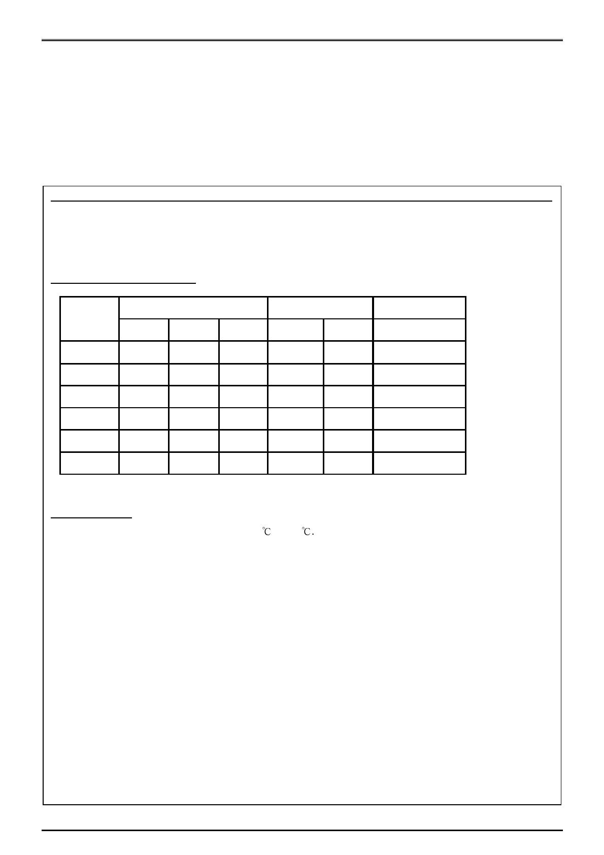
OUTPUT CHARACTERISTICS:
O U T P U T C U R REN T(A ) R EG U LA T IO N O U T P U T
M IN .
M A X .
PEA K
LO AD LIN E
5V 3 35
±
5%
±
1%
50m V
12V 2
22 /26 /3 0
+7% /-5%
± 1%
120m V
-5V 0 0.8
±
5%
±
1%
150m V
-12V 0 1.0
± 5% ± 1%
150m V
3.3V 1 25
±
5%
±
1%
50m V
+5V S B 0.1 2
±
5%
±
1%
50m V
O UTP U T
VO LT A G E
R IPP LE & N O ISE
M A X . [P-P]
REMARK: THE OUTPUT CURRENT OF 5V & 3.3V SHOULD NOT EXCEED 45A.
SPECIFICATION:
TEMPERATURE RANGE: OPERATING 0 --- 40
HOLD UP TIME: 16 ms MINIMUM AT FULL LOAD & NORMAL INPUT VOLTAGE.
DIELECTRIC WITHSTAND: INPUT / OUTPUT 1500 VAC FOR 1 SECOND.
INPUT TO FRAME GROUND 1500 VAC FOR 1 SECOND.
EFFICIENCY: 68% TYPICAL.
POWER GOOD SIGNAL: ON DELAY 100 ms TO 500 ms, OFF DELAY 1 ms.
OVER LOAD PROTECTION: 130 +/- 20%.
OVER VOLTAGE PROTECTION:
+5V
5.7V ~ 6.5V, 3.3V
3.9 ~ 4.3V, 12V
13.6 ~ 15V.
SHORT CIRCUIT PROTECTION: +5V, -5V, +12V, -12V, +3.3V.
EMI NOISE FILTER: FCC CLASS B, CISPR22 CLASS B.
SAFETY: UL 1950, CSA 22.2 NO/ 950, TÜV IEC 950.
REMOTE ON / OFF CONTROL.
THE UNIT SHALL ACCEPT A LOGIC OPEN COLLECTOR LEVEL WHICH WILL DISABLE / ENABLE ALL
OUTPUT VOLTAGES (EXCLUDE +5V STANDBY),
AS LOGIC LEVEL IS LOW, OUTPUTS VOLTAGE WERE ENABLE,
AS LOGIC LEVEL IS HIGH, OUTPUTS VOLTAGE WAS DISABLE.
3.3V / 5V REMOTE SENSING.
COOLING: ONE 80mm BALL BEARING DC FAN.
DIMENSION: 140 (D) x150 (W) x 86 (H) mm (PS/2).
ACTIVE POWER FACTOR CORRECTION MEET IEC-1000-3-2 CLASS D.
ADVANCE THERMAL & ACOUSTICS CONTROL FEATURES.


