Centro ADVANCE 1000-HV User manual
- Type
- User manual

EK459B01
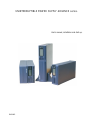
User's manual, installation and start-up.
UNINTERRUPTIBLE POWER SUPPLY ADVANCE series.

- 2 -

- 3 -
General contents.
1.- INTRODUCTION.
1.1.- Gratefulness letter
1.2.- Using this manual.
1.2.1.- Used symbols and conventions.
1.2.2.- For further information and/or help.
2.- QUALITY AND STANDARD GUARANTEING.
2.1.- Management declaration.
2.2.- Standard.
2.3.- Safety and first aid.
2.4.- Environment.
3.- DESCRIPTION.
4.- PRESENTATION OF SYSTEM.
4.1.- Front Panel.
4.2.- Introducing the LCD display.
4.3.- Audible alarm introduction.
4.4.- Back panel.
5.- INSTALLATION.
5.1.- Inspecting the Equipment.
5.2.- Placement.
5.3.- Charging.
5.3.1.- Load connection.
5.4.- Modem/Phoneline Connection.
5.5.- DC Start function.
5.6.- Turn On/Off.
5.7.- UPS Setup.
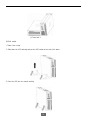
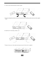
5.7.1- Tower Setup.
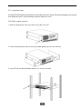
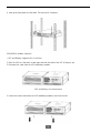
5.7.2.- Rack-Mount Setup.
5.8.- Emergency Power Off (E.P.O.) set up.
6.- ADDITIONAL BATTERY INSTALLATION SETUP.
7.- BATTERY REPLACEMENT.
8.- COMMUNICATION PORT.
8.1.- RS232 + Optocouplers.
8.2.- USB port: HID protocol.
8.3.- AS400 interface (Optional). Not available for models lower than 1500 VA.
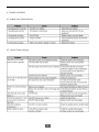
9.- TROUBLE SHOOTING.
9.1.- Audible Alarm Trouble Shooting.
9.2.- General Trouble Shooting.
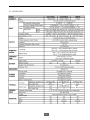
10.- SPECIFICATION.
11.- SOFTWARE INSTALLATION.

- 4 -
1.- INTRODUCTION.
1.1.- Gratefulness letter.
We would like to thank you in advance for the trust you have placed in us by purchasing this product. Read this instruction
manual carefully before starting up the equipment and keep it for any possible future consult that can arise.
We remain at you entire disposal for any further information or any query you should wish to make.
Yours sincerely,
The equipment here described can cause important physical damages due to wrong handling. Due to this, the maintenance
and/or fixing of the here described equipment must be done by SALICRU staff or specifically authorised.
According to our policy of constant evolution, we reserve the right to modify the specifications in part or in whole without
forewarning.
All reproduction or third party concession of this manual is prohibited without the previous written authorization of our firm.
1.2.- Using this manual.
The purpose of this manual is to provides explanations and procedures for the installation, commissioning, maintenance
and troubleshooting of UPS from ADVANCE series. This manual has to be read carefully before installing and operating it.
Keep this manual for future consults.
This manual consists into four main chapters:
• Introduction, it contents the information of the general description, features and specifications of UPS ADVANCE series.
• Installation and Operating, it provides the information of the commissioning and operating of UPS ADVANCE series, as
well as its connection.
• Maintenance and Troubleshooting, it contents the information to maintain and solve wrong operating and parts faults
of UPS ADVANCE series.
• Annexes, it contents the specification table and the appendices.
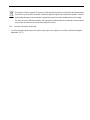
1.2.1.- Used symbols and conventions.
«Warning» symbol. Carefully read the indicated paragraph and take the stated prevention measures.
«Danger of electrical discharge» symbol. Pay special attention to it, both in the indication on the equipment and
in the paragraph referred to this user’s manual.
«Main protective earthing terminal» symbol. Connect the earth cable coming from the installation to this terminal.
«Notes of information» symbol.
SALICRU

- 5 -
Preservation of the environment: The presence of this symbol in the product or in their associated documentation
states that, when its useful life is expired, it will not be disposed together with the domestic residuals. In order to
avoid possible damages to the environment, separate this product from other residuals and recycle it suitably.
The users can contact with their provider or with the pertinent local authorities to be informed on how and where
they can take the product to be recycled and/or disposed correctly.
1.2.2.- For further information and/or help.
• For further information and/or help on the version of your specific unit, request it to our Service and Technical Support
department (S.T.S.).

- 6 -
2.- QUALITY AND STANDARD GUARANTEING.
2.1.- Management declaration.
Our target is the client’s satisfaction, therefore this Management has decided to establish a Quality and Environmental policy,
by means of installation a Quality and Environmental Management System that becomes us capable to comply the require-
ments demanded by both the standards ISO 9001:2000 and ISO 14001:2004 and our Clients and concerned parts too.
Likewise, the SALICRU Management is committed with the development and improvement of the Quality and Environmental
Management System, through:
• The communication to all the company about the importance of satisfaction both in the client’s requirements and in the
legal and regulations.
• The Quality and Environmental Policy diffusion and the fixation of the Quality and Environment targets.
• To carry out revisions by the Management.
• To provide the needed resources.
Management agent
The Management has designated as management agent the person in charge about the Quality and Environment depart-
ment, who with independence of other responsibilities, has the responsibility and authority: to assure that the processes of
the quality and environmental management system are established and maintained; to inform to the Management about the
operating of the quality and environmental management system, including the necessities for the improvement; and to
promote the knowledge of the client’s requirements and environmental requirements at all levels of the organization.
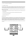
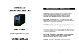
In the next PROCESS MAP is represented the interaction among all the processes of the Quality and Environmental System
of SALICRU:
PROCESO FORMACION
CLIENTES
CLIENTES:
- PRODUCTO
- SERVICIO
PROCESO COMERCIAL PROCESO FABRICACION
PROCESO LOGISTICA INTERNA
PROCESO MANTENIMIENTO
PROCESO MEJORA CONTINUA / REVISION DIRECCION
PROCESO GESTION CALIDAD
PROCESO GESTION
MEDIOAMBIENTE
PROCESO R & D PROCESO OFICINA TECNICA
CONTINUOUS IMPROVEMENT PROCEDURE /
MANAGEMENT REVISION
QUALITY MANAGEMENT
PROCESS
ENVIRONMENT
MANAGEMENT PROCESS
CLIENTS:
- PRODUCT
- SERVICE
TECHNICAL OFFICE
PROCESS
PRODUCTION
PROCESS
R&D
PROCESS
COMMERCIAL
PROCESS
CLIENTS
INTERNAL LOGISTIC PROCESS
MAINTENANCE PROCESS
TRAINING PROCESS

- 7 -
2.2.- Standard.
The UPS productADVANCE series is designed, manufactured and commercialized in accordance with the standardEN ISO
9001 of Quality Assurance. The
marking shows the conformity to the EEC Directive (quoted between brackets) by means
of the application of the following standards:
• 2006/95/EC of Security of Low Tension.
• 2004/108/EC of Electromagnetic Compatibility (CEM).
according to the specifications of the harmonious standards. Reference of standards:
• IN 60950-1: Equipments of technology of the information. Security. Part(report) 1: General Requirements.
• IN 61000-6-3: Electromagnetic Compatibility. General emission standard. Residential, commercial and light industry
environments.
• IN 61000-6-2: Electromagnetic Compatibility. Generic standard of immunity. Industrial environment.
When a UPS of ADVANCE series is used as part or component of a complex system or installation, the Generic or Product
standards of that installation or specific system must be applied.
It is possible that when adding parts, or being under the requirements of a specific standard, all the parts have to be under
corrections to assure the conformity with the European Directives and the corresponding national regulations. It is responsi-
bility of the project Manager and/or Fitter, the compliance of the standard, providing to the installation all the needed
parts to comply the standard.
Furthermore, the interference phenomena due to input harmonic currents exists, and although it is not regulated by these
standards, it is necessary to correct them in some installations.
Depending on the installation conditions of UPS ADVANCE series, the corrections described in the Electromagnetic Compat-
ibility have or do not have to be done. For all the versions and regarding the Safety (standard EN 60950-1) has to be kept in
mind the aspects of the Product detailed in the INSTALLATION section.
2.3.- Safety and first aid.
• Together with the equipment and this «User and installation manual», it is provided the information relating to «Safety
instructions» (See document EK266*08). Before proceeding to the installation or commissioning, check that both infor-
mation are available; otherwise request them. It is compulsory the compliance of the «Safety instructions», being the user
the legal responsible regarding to its observance. Once read, keep them for future consults that can arise.
•
Do not attempt to repair and service this UPS. This UPS contains high voltages which could cause the risk of
electrical shock. Even this UPS is disconnected from the electrical outlet, the dangerous voltage still may be present
through the battery. All maintenance and battery replacement should be performed by qualified service personnel only.
•
This is a class A product. In domestic use, this product can cause radioelectric disturbs and, in this case, the user
must take additional measures.
• This UPS is designed for Commercial/Industrial use only. It is not intended for use with life support application and other
designated «life-critical» devices.
• Do not remove the input power cord when this UPS is turned on. This removes the safety ground from this UPS and the
equipment connected to UPS.

- 8 -
• When replacing the batteries, use the appropriate replacement battery kits, same number and type of battery are MUST.
Turn off this UPS and disconnect input power cord before battery replacement.
• During the installation of this equipment it should be assured that the sum of the leakage currents of the UPS and the
connected loads does not exceed 3.5mA.
2.4.- Environment.
This product has been designed to respect the environment and has been manufactured in accordance with the standard ISO
14001.
Recycling the UPS ADVANCE series at the end of its useful life:
SALICRU commits to use the services of authorised societies and according to the regulations, in order to treat the recovered
product at the end of its useful life (contact your distributor).
Packing:
To recycle the packing, follow the legal regulations in force.
Batteries:
The batteries mean a serious danger for health and environment. The disposal of them must be done in accordance with the
standards in force.

- 9 -
3.- DESCRIPTION
This series is a compact and fully pure sinewave line interactive UPS, and it designs for application and environment, such as
desktops, servers, workstations, and other networking equipments. This model is available in the output ratings of 750, 1000,
1500, 2000, and 3000VA. This series protects your sensitive electronic equipments against power problems including power
sags, spike, brownouts, line noise, and blackouts.
This series designs from two-in-one form factor; it can be placed either in Rack 2U or Tower. The front panel of the UPS includes
LED indicators and four push buttons (Power Switch, UPS Test/Silence, Configure, and Enter) that allow to monitor easily,
configuration and control, AC line-in, notification of site wiring fault and output load status of the UPS. It also includes four LCD
bar graphic (Load/Battery Level Indication); two status indications (On AC, On Battery); five alarm indications (Overload, Over
Temperature, Site Wiring Fault, Battery Fault, Self Test Failure). A push button from the front panel allows silencing of the AC
fail alarm and the initiation of the UPS self test sequence as well. The UPS case for 750 ~ 2000VA is made of plastic as well
as 3000VA is made of metal.
This series is powered from the AC mains and supply AC outputs via receptacles on the rear panel. Communication and control
to the unit is available through serial or USB ports located on the rear panel. The serial port will support communications directly
with a server. The communications protocol for the serial ports shall conform to true RS232 interface.
• Features:
Microprocessor control guarantees high reliability.
High frequency design.
Built-in boost and buck AVR.
User replaceable design for 1500VA or above.
Selectable output range and line sensitive.
Cold startup capability.
Optocouplers/RS-232/USB communication port.
SNMP allows for web-based remote or monitoring management.
Enable to extend runtime with scalable external battery pack for 1500VA or above.
Overload, Short-circuit, and overheat protection.
• Rack/Tower 2 in 1 Design.
• 19" rack mount available for all models.

- 10 -
4.- PRESENTATION OF SYSTEM.
4.1.- Front Panel.
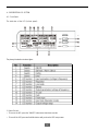
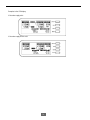
The total view of the LCD (in front panel):
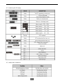
The primary introduction to above figure:
1. Power Switch:
• To turn on the UPS, press the “ON/OFF” button more than three seconds.
• To turn off the UPS, press and hold this button until you hear the UPS beep ceases.

- 11 -
2. UPS Test/ Alarm Silence Switch:
• When AC utility power is available and battery is full charged, it is possible to perform self-test function by pressing and
holding the “TEST” button for five seconds.
• To disable alarm buzzer, press this button for a second that will turn off the alarm buzzer. Each time a new alarm event is
encountered the alarm that will sound and press this button to turn off the alarm.
Note: Unable to disable alarm buzzer as below conditions: Low Battery, Overload, Fan Failed, Fan Fault Time Out, Over
Temperature.
3. Configure switch:
To reconfigure the internal UPS setup options, follow the procedure as below:
Step 1: By entering the “CNFG” button more than three seconds, UPS will transfer to “Rated voltage” configure mode.
Step 2: Pressing the “CNFG” button more than one second, the UPS allows you to select the “Rated voltage one by one.
Step 3: After selecting the mode, press the “ENTER” button more than three seconds, the “Rated voltage” is configured.
Step 4: UPS will automatically transfer to “Input type” configure mode.
Step 5: Pressing the “CNFG” button more than one second, the UPS will allow you to select the “Input type” one by one.
Step 6: After selecting the mode, press the “ENTER” button more than three seconds, the “Input type” is configured.
4. Enter switch:
Press the «ENTER» button after you choose the mode.
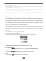
5. Input parameters (voltage & frequency):
This part gives the information of the AC utility power, including input voltage and input frequency.
The figure indicates that the input voltage is 230V and the input frequency is 50Hz.
6. Auto Voltage Regulation:
The LCD symbol
indicates that the UPS is in AVR (Auto Voltage Regulation) mode.
7. Line Mode:
The LCD symbol
illuminates when UPS is on and the AC source is available.
8. Battery:
• The LCD symbol
indicates that the battery is in charging mode.

- 12 -
• The LCD symbol indicates that the battery is working(the AC source is not available),and it will flicker every
second when battery is low.
• The battery symbol also could show battery level: There are four segments to indicate the amount of battery capacity
remaining. The higher the battery capacity, the more indicators that will be illuminated. Each indicator designates a 25%
capacity level. Please see the following capacity level respectively. This is:
- 100% to 76%
, all of the four indicators illuminate..
- 75% al 51%
, three indicators illuminate.
- 50% al 26% , two indicators illuminate.
- 25% al 11% , only one indicator illuminates.
- 10% al 0% , none of the indicator illuminates.
When the battery is empty, the symbol will flicker every second.
9. Output paremeters (voltage & frequency):
This part gives the information of the output, including output voltage and output frequency.
The figure indicates that the output voltage is 230V and the output frequency is 50Hz.
10. Capacity of Load:
The LCD gives the load information by displaying the load percentage.
Normally, the symbol will not illuminate, but when the load percentage is more than 110% (overload),it will flicker
every second. If over load is time out , it will illuminate constantly
11. Site Fault:
The Site Fault indicator
will light when UPS is plugged into an improperly utility..
This function is only available for 120Vac models.
12. Fault code:
When UPS fails, the corresponding LCD symbol will illuminate to show the type of failure.
• Battery bad: When the battery of the UPS is bad, the symbol
will be displayed constantly..

- 13 -
• Over load time out: When UPS is Over load time out, the symbol will be displayed constantly. At the
same time, the symbol
will be displayed constantly, and the output voltage is 0Vac 0Hz.
• Battery missing: If the battery connection is not good, the LCD will display “FAULT CODE 1”.
• Fan fail: If the fan is locked, The symbol “FAULT CODE 2” will flicker every second; if the time is out. Thesymbol will
be displayed constantly.
• Over temperature: If the temperature of the UPS is too high, The LCD will display “FAULT CODE 3” constantly.
• Output invalid: If output voltage is out of range, the LCD will display “FAULT CODE 4” constantly.
• Battery overcharged: The LCD will display “FAULT CODE 5” constantly.
• Output short circuit: The LCD will display “FAULT CODE 6” constantly.
• Other fault type: The LCD will display “FAULT CODE 8” constantly.
13. Input type (Operation mode):
• Normal: The UPS accepts a input voltage range of ±20%.
• Generator: The low frequence transfer point changes at 40Hz and there is not limit for the high frecuence transfer point.
• Extended margin: The UPS accepts a input voltage margin of -30% to +20%.
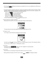
14. Output voltage margin:
The UPS output voltage selection:110Vac/120Vac/127Vac o 220Vac/230Vac/240Vac.
110Vac/120Vac/127Vac are LV mode (low voltage).
220Vac/230Vac/240Vac are HV mode (high voltage).
Example: To a HV UPS, after selection the 230Vac mode (default selection) by the switchs "CNFG" and "ENTER", the
output voltage will be approximately 230V, and the LCD display will be how the next figure shows:

- 14 -
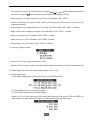
Examples to the LCD display:
If the mains supply exist:
If the mains supply do not exist:

- 15 -
4.2.- Introducing the LCD display.
4.3.- Audible alarm introduction.
polarity

- 16 -
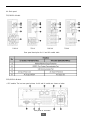
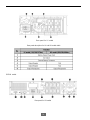
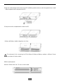
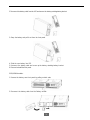
4.4.- Back panel.
750/1000VA Models
1000-LV 750-LV 1000-HV 750-HV
Rear panel description for LV and HV models table
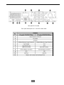
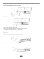
1500/2000VA Models.
• UPS module: The host rear panel pictures for HV and LV models are shown as below:
Rear panel for HV model

- 17 -
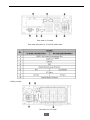
Rear panel for LV model
Rear panel description for LV and HV models table
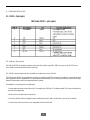
• Battery module.
Rear panel for HV model
or AS400

- 18 -
Rear panel for LV model
Rear panel description for LV and HV models table
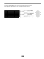
3000VA model.
Rear panel for HV model

- 19 -
Rear panel for LV model
Rear panel description for LV and HV models table
SNMP Slot or AS400 SNMP Slot or AS400

- 20 -
5.- INSTALLATION.
5.1.- Inspecting the Equipment.
Inspect the UPS upon receipt. If the UPS has been damaged during shipment, keep the box and packing material for the
carrier. Notify the carrier and dealer immediately.
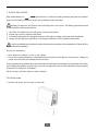
5.2.- Placement.
This UPS should be installed indoors with adequate airflow and free of contamination. Locate it in a clean and indoor
environment, free from moisture, flammable liquids, and direct sunlight. Maintain a minimum clearance of 4 inches (100mm);
an ambient temperature range must be 0°C to 40°C (32°F to 104°F), and operating humidity range must be 20% to 80%
relative humidity (non-condensing).
The long term uses at ambient temperature in higher than 25°C which should reduce battery life. In addition, place
the UPS unit away from the monitor at least 20cm. to avoid interference.
5.3.- Charging.
This UPS is shipped from the factory with its internal battery fully charged; however, some charge may be lost during shipping.
The battery should be recharged prior to use. Plug the UPS into an appropriate power supply and allow the UPS to charge at
least 4 hours.
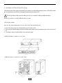
5.3.1.- Load connection.
Connect one load-related device to each of the power receptacles supplied at the rear of the UPS.
5.4.- Modem/Phoneline Connection.
Plug incoming telephone line into the “In” socket at the back of the UPS. Use on telephone line cable and plug one end of the
telephone line cable to the “Out” socket at the back of the UPS. Plug the other end to the modem input socket.
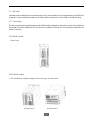
5.5.- DC Start function.
DC Start Function enables UPS to be started up when AC utility power is not available and battery is full charged. Just simply
press the On/Off switch to turn on the UPS.
5.6.- Turn On/Off.
To turn on/off the UPS, you should press the on/off switch three seconds at least.
Page is loading ...
Page is loading ...
Page is loading ...
Page is loading ...
Page is loading ...
Page is loading ...
Page is loading ...
Page is loading ...
Page is loading ...
Page is loading ...
Page is loading ...
Page is loading ...
Page is loading ...
Page is loading ...
Page is loading ...
Page is loading ...
Page is loading ...
Page is loading ...
Page is loading ...
Page is loading ...
-
 1
1
-
 2
2
-
 3
3
-
 4
4
-
 5
5
-
 6
6
-
 7
7
-
 8
8
-
 9
9
-
 10
10
-
 11
11
-
 12
12
-
 13
13
-
 14
14
-
 15
15
-
 16
16
-
 17
17
-
 18
18
-
 19
19
-
 20
20
-
 21
21
-
 22
22
-
 23
23
-
 24
24
-
 25
25
-
 26
26
-
 27
27
-
 28
28
-
 29
29
-
 30
30
-
 31
31
-
 32
32
-
 33
33
-
 34
34
-
 35
35
-
 36
36
-
 37
37
-
 38
38
-
 39
39
-
 40
40


Centro ADVANCE 1000-HV User manual
- Type
- User manual
Ask a question and I''ll find the answer in the document
Finding information in a document is now easier with AI
Other documents
-
BlueWalker PowerWalker VI 2000RT LCD User manual
-
 AVIEM Systems PRO 1000VA User manual
-
 Minute Man PRO-RT User manual
-
Minuteman Endeavor ED1000RTXL2U User manual
-
Salicru SLC-8000 TWIN PRO User manual
-
 Adams 1000VA User manual
-
 Adams 1000VA User manual
-
Mustek 98-0CD-PR100 Datasheet
-
-
Salicru SLC-700-TWIN RT (B1) User manual


