Preface
Preface
Copyright
This publication, including all photographs, illustrations and software, is protected
under international copyright laws, with all rights reserved. Neither this manual, nor
any of the material contained herein, may be reproduced without written consent of
the author.
Version 1.0
Disclaimer
The information in this document is subject to change without notice. The manufac-
turer makes no representations or warranties with respect to the contents hereof and
specifically disclaims any implied warranties of merchantability or fitness for any
particular purpose. The manufacturer reserves the right to revise this publication and
to make changes from time to time in the content hereof without obligation of the
manufacturer to notify any person of such revision or changes.
Trademark Recognition
Microsoft, MS-DOS and Windows are registered trademarks of Microsoft Corp.
MMX, Pentium, Pentium-II, Pentium-III, Celeron are registered trademarks of Intel
Corporation.
Other product names used in this manual are the properties of their respective
owners and are acknowledged.
Federal Communications Commission (FCC)
This equipment has been tested and found to comply with the limits for a Class B
digital device, pursuant to Part 15 of the FCC Rules. These limits are designed to
provide reasonable protection against harmful interference in a residential installa-
tion. This equipment generates, uses, and can radiate radio frequency energy and, if
not installed and used in accordance with the instructions, may cause harmful inter-
ference to radio communications. However, there is no guarantee that interference
will not occur in a particular installation. If this equipment does cause harmful
interference to radio or television reception, which can be determined by turning the
equipment off and on, the user is encouraged to try to correct the interference by one
or more of the following measures:
• Reorient or relocate the receiving antenna
• Increase the separation between the equipment and the receiver
• Connect the equipment onto an outlet on a circuit different from that to
which the receiver is connected
• Consult the dealer or an experienced radio/TV technician for help
Shielded interconnect cables and a shielded AC power cable must be employed with
this equipment to ensure compliance with the pertinent RF emission limits governing
this device. Changes or modifications not expressly approved by the system’s manu-
facturer could void the user’s authority to operate the equipment.

ii
Preface
Declaration of Conformity
This device complies with part 15 of the FCC rules. Operation is subject to the
following conditions:
• This device may not cause harmful interference, and
• This device must accept any interference received, including interfer-
ence that may cause undesired operation
Canadian Department of Communications
This class B digital apparatus meets all requirements of the Canadian Interference-
causing Equipment Regulations.
Cet appareil numérique de la classe B respecte toutes les exigences du Réglement sur
le matériel brouilieur du Canada.
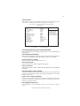
About the Manual
The manual consists of the following:
Chapter 1
Introducing the Motherboard
Chapter 2
Installing the Motherboard
Chapter 3
Using BIOS
Chapter 4
Using the Motherboard Software
Describes features of the
motherboard.
Go to
H
page 1
Describes installation of
motherboard components.
Go to
H
page 7
Provides information on us-
ing the BIOS Setup Utility.
Go to
H
page 27
Describes the motherboard
software
Go to
H
page 43

iii
Chapter 2
7 7
7 7
7
Installing the Motherboard 7
Safety Precautions...........................................................................7
Choosing a Computer Case............................................................7
Installing the Motherboard in a Case............................................7
Checking Jumper Settings...............................................................8
Setting Jumpers...................................................................8
Checking Jumper Settings...................................................9
Jumper Settings...................................................................9
Installing Hardware........................................................................10
Installing the Processor.....................................................10
Installing Memory Modules...............................................12
Expansion Slots.................................................................15
Connecting Optional Devices............................................17
Installing a SATA Hard Drive...........................................20
Installing a Floppy Diskette Drive....................................21
Connecting I/O Devices................................................................22
Connecting Case Components.....................................................23
Front Panel Header...........................................................25
TT
TT
T
ABLE OF CONTENTSABLE OF CONTENTS
ABLE OF CONTENTSABLE OF CONTENTS
ABLE OF CONTENTS
Preface i
Chapter 1 1
Introducing the Motherboard 1
Introduction......................................................................................1
Feature...............................................................................................2
Motherboard Components.............................................................5
Chapter 3 27
Using BIOS 27
About the Setup Utility................................................................ 27
The Standard Configuration..............................................27
Entering the Setup Utility...................................................27
Using BIOS......................................................................................28
Standard CMOS Setup......................................................29
Advanced Setup.................................................................31
Advanced Chipset Setup....................................................33

iv
Integrated Peripherals.......................................................34
Power Management Setup.................................................35
PCI/PnP Setup...................................................................36
PC Health Status...............................................................37
Frequency/Voltage Control...............................................39
Load Default Settings........................................................40
Supervisor Password........................................................40
User Password..................................................................4
1
Save & Exit Setup..............................................................41
Exit Without Saving............................................................41
Updating the BIOS.............................................................42
Chapter 4
43 43
43 43
43
Using the Motherboard Software 43
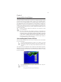
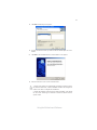
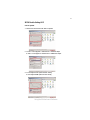
About the Software CD-ROM......................................................43
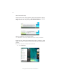
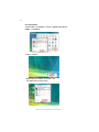
Auto-installing under Windows XP/Vista..................................43
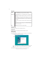
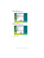
Running Setup....................................................................44
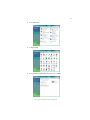
Manual Installation........................................................................48
Utility Software Reference............................................................48
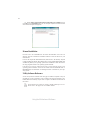
HDMI Audio Setting SOP.............................................................49

1
Introducing the Motherboard
Chapter 1
Introducing the Motherboard
Introduction
Thank you for choosing the G45T-M2 motherboard. This motherboard is a high
performance, enhanced function motherboard designed to support the LGA775 socket
Intel
®
Yorkfield/Wolfdale/Core
™
2 Quad/Core
™
2 Duo/Pentium
®
Dual-Core (E21XX
series)/Celeron
®
Dual-Core/Celeron
®
4xx processors for high-end business or per-
sonal desktop markets.
The motherboard incorporates the G45 Northbridge (NB) and ICH10 Southbridge
(SB) chipsets. The Northbridge supports a Front Side Bus (FSB) frequency of 1333/
1066/800 MHz using a scalable FSB Vcc_CPU. The memory controller supports
DDR2 memory DIMM frequencies of 800/667. It supports four DDR2 Sockets with
up to maximum memory of 16 GB. DDR2 Maximum memory bandwidth of 12.8 GB/
s in dual-channel symmetric mode assuming DDR2 800 MHz. High resolution graph-
ics via one PCI Express slot, intended for Graphics Interface, is fully compliant to
the PCI Express Base Specification revision 2.0.
The ICH10 Southbridge supports two PCI slots which are PCI 2.3 compliant. In
addition, one PCI Express x1 slot is supported. It implements an EHCI compliant
interface that provides 480 Mb/s bandwidth for 12 USB 2.0 ports (4 USB ports and
4 USB 2.0 headers support additional 8 USB ports). The Southbridge integrates a
Serial ATA host controller, supporting six SATA ports with maximum transfer rate up
to 3.0 Gb/s each.
The motherboard is equipped with advanced full set of I/O ports in the rear panel,
including PS/2 mouse and keyboard connectors, one DVI port, one VGA port, four
USB ports, one LAN port and audio jacks for microphone, line-in and 6/8-channel
(optional) line-out.

2
Introducing the Motherboard
Feature
• Accommodates Intel
®
Yorkfield/Wolfdale/Core
™
2 Quad/Core
™
2 Duo/
Pentium
®
Dual-Core (E21XX series)/Celeron
®
Dual-Core/Celeron
®
4xx
processors
• Supports a system bus (FSB) of 1333/1066/800 MHz
• Supports “Hyper-Threading” technology CPU
The motherboard uses an LGA775 type of Intel
®
Yorkfield/Wolfdale/Core
™
2
Quad/Core
™
2 Duo/Pentium
®
Dual-Core (E21XX series)/Celeron
®
Dual-Core/
Celeron
®
4xx processors that carries the following features:
Processor
The G45 Northbridge (NB) and ICH10 Southbridge (SB) chipsets are based on an
innovative and scalable architecture with proven reliability and performance.
Chipset
ICH10
(SB)
• Enhanced DMA Controller, Timer/Counter functions, and In-
terrupt Controller
• Compliant with PCI Express Base Specification, Revision
1.1
• Compliant with PCI 2.3 specification
• Integrated SATA 3.0 Gb/s Host Controller
• Integrated USB 2.0 Host Controller supporting up to twelve
USB 2.0 ports
• Supports DDR2 800/667 DDR SDRAM with Dual-channel architecture
• Accommodates four unbuffered DIMMs
• Up to 4 GB per DIMM with maximum memory size up to 16 GB
Memory
G45
“Hyper-Threading” technology enables the operating system into thinking it’s
hooked up to two processors, allowing two threads to be run in parallel, both on
separate “logical” processors within the same physical processor.
• Supports 36-bit host bus addressing, allowing the CPU to
access the entire 64 GB of the memory address space
• 2 GB/s point-to-point Direct Media Interface (DMI) to ICH10
(1 GB/s each direction)
• Supports 512-Mb, 1-Gb and 2-Gb DDR2 and 512-Mb and 1-
Gb DDR3 technologies for x8 and x16 devices
• One, 16-lane (x16) PCI Express port intended for support-
ing up to two external PCI Express graphics card in bifur-
cated mode, filly compatible to the PCI Express Base Speci-
fication revision 2.0
• An integrated graphics device (IGD) delivering cost com-
petitive 3D, 2D and video capabilities
(NB)

3
Introducing the Motherboard
Onboard LAN (optional)
Audio (optional)
The motherboard comes with the following expansion options:
• One PCI Express x 16 slot for Graphic Interface
• One PCI Express x1 Slot
• Two 32-bit PCI v2.3 compliant slots
• Six 7-pin SATA connectors
Expansion Options
• One DVI port
• One VGA port
• One Parallel port
• Four USB ports
• One LAN port
• Audio jacks for microphone, line-in and 6/8-channel (optional) line-out
The motherboard has a full set of I/O ports and connectors:
Integrated I/O
• Two PS/2 ports for mouse and keyboard
This motherboard supports Ultra DMA bus mastering with transfer rates of 133/
100/66/33 Mb/s.
This motherboard may support either of the following Audio chipsets:
• 7.1 + 2 channel High Definition Audio Codec
• All DACs Support 192k/96k/48k/44.1kHz DAC sample rate
• High-quality analog differential CD input
• Meets Microsoft WHQL/WLP 3.0 audio requirements
• Direct Sound 3D
TM
compatible
• 7.1+2 channel High Definition Audio Codec
• All DACs Support 192k/96k/48k/44.1kHz DAC sample rate
• Software selectable 2.5V/3.75V VREFOUT
• Meets Microsoft WHQL/WLP 2.x audio requirements
• Direct Sound 3D
TM
compatible
• 5.1 Channel High Definition Audio Codec
• ADCs support 44.1k/48k/96kHz sample rate
• Meets Microsoft WLP 3.08 Vista premium and mobile PCs audio re-
quirements
• Direct Sound 3D
TM
compatible
• Integrated Fast Ethernet Controller for PCI Express
TM
Applications
• Integrated 10/100 transceiver
• Wake-on-LAN and remote wake-up support
• Integrated Gigabit Ethernet Controller for PCI Express
TM
Applications
• Integrated 10/100/1000 transceiver
• Wake-on-LAN and remote wake-up support
This motherboard may support either of the following LAN chipsets:

4
Introducing the Motherboard
• Power management
• Wake-up alarms
• CPU parameters
• CPU and memroy timing
BIOS Firmware
This motherboard uses AMI BIOS that enables users to configure many system
features including the following:
The firmware can also be used to set parameters for different processor clock
speeds.
1. Some hardware specifications and software items are subject to change
without prior notice.
2. Due to chipset limitation, we recommend that motherboard be oper-
ated in the ambiance between 0 and 50 °C.

5
Introducing the Motherboard
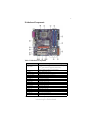
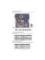
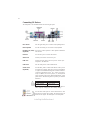
Motherboard Components
Table of Motherboard Components
This concludes Chapter 1. The next chapter explains how to install the motherboard.
LABEL COMPONENTS
LGA775 socket for Intel
®
Yorkfield/Wolfdale/Core
TM
2 Quad/
Core
TM
2 Duo/Pentium
®
Dual-Core (E21XX series)/
Celeron
®
Dual-Core/Celeron
®
4xx series CPUs
2. CPU_FAN CPU cooling fan connector
3. DIMM1~4 240-pin DDR2 SDRAM slots
4. FDD1 Floppy disk drive connector
5. ATX_POWER1 Standard 24-pin ATX power connector
6. SATA1~6 Serial ATA connectors
7. F_PANEL Front panel switch/LED header
8. F_USB1~4 Front Panel USB headers
9. CLR_CMOS Clear CMOS jumper
10. BIOS_WP BIOS flash protect header
11. COM1 Onboard serial port header
12. CD_IN Analog audio input connector
13. F_AUDIO Front panel audio header
14. SPDIF_OUT SPDIF out header
15. PCI1~2 32-bit add-on card slots
16. PCIEX1 PCI Express x1 slot
17. PCIE1 PCI Express x16 graphics card slot
18. ATX12V1 4-pin +12V power connector
19. SYS_FAN System cooling fan connector
1. CPU Socket

6
Introducing the Motherboard
Memo

7
Installing the Motherboard
Chapter 2
Installing the Motherboard
Safety Precautions
• Follow these safety precautions when installing the motherboard
• Wear a grounding strap attached to a grounded device to avoid dam-
age from static electricity
• Discharge static electricity by touching the metal case of a safely
grounded object before working on the motherboard
• Leave components in the static-proof bags they came in
• Hold all circuit boards by the edges. Do not bend circuit boards
Choosing a Computer Case
There are many types of computer cases on the market. The motherboard complies
with the specifications for the Micro ATX system case. First, some features on the
motherboard are implemented by cabling connectors on the motherboard to indica-
tors and switches on the system case. Make sure that your case supports all the
features required. Secondly, this motherboard supports two enhanced IDE drives.
Make sure that your case has sufficient power and space for all drives that you intend
to install.
Most cases have a choice of I/O templates in the rear panel. Make sure that the I/O
template in the case matches the I/O ports installed on the rear edge of the
motherboard.
This motherboard carries a Micro ATX form factor of 244 x 244 mm. Choose a case
that accommodates this form factor.
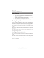
Installing the Motherboard in a Case
Refer to the following illustration and instructions for installing the motherboard in
a case.
Most system cases have mounting brackets installed in the case, which correspond
the holes in the motherboard. Place the motherboard over the mounting brackets
and secure the motherboard onto the mounting brackets with screws.
Ensure that your case has an I/O template that supports the I/O ports and expansion
slots on your motherboard.

8
Installing the Motherboard
Checking Jumper Settings
This section explains how to set jumpers for correct configuration of the motherboard.
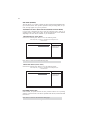
Setting Jumpers
Use the motherboard jumpers to set system configuration options. Jumpers with
more than one pin are numbered. When setting the jumpers, ensure that the jumper
caps are placed on the correct pins.
The illustrations show a 2-pin jumper. When
the jumper cap is placed on both pins, the
jumper is SHORT. If you remove the jumper
cap, or place the jumper cap on just one pin,
the jumper is OPEN.
This illustration shows a 3-pin jumper. Pins
1 and 2 are SHORT.
SHORT OPEN
Do not over-tighten the screws as this can stress the motherboard.

9
Installing the Motherboard
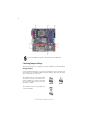
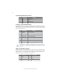
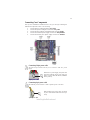
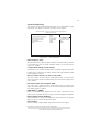
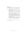
Checking Jumper Settings
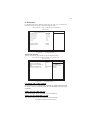
The following illustration shows the location of the motherboard jumpers. Pin 1 is
labeled.
Jumper Settings
Jumper
Type
Description
Setting (default)
CLR_CMOS 3-pin CLEAR CMOS
1-2: NORMAL
2-3: CLEAR
OPEN: WRITE
UNPROTECT
SHORT: WRITE
PROTECT
BIOS PROTECT2-pinBIOS_WP
Before clearing the CMOS,
make sure to turn off the
system.
BIOS_WP
1
CLR_CMOS
1
To avoid the system instability after clearing CMOS, we recommend
users to enter the main BIOS setting page to “Load Optimized Defaults”
and then “Save & Exit Setup”.

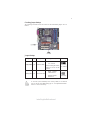
10
Installing the Motherboard
Installing Hardware
Installing the Processor
Caution: When installing a CPU heatsink and cooling fan make sure
that you DO NOT scratch the motherboard or any of the surface-
mount resistors with the clip of the cooling fan. If the clip of the
cooling fan scrapes across the motherboard, you may cause serious
damage to the motherboard or its components.
On most motherboards, there are small surface-mount resistors near
the processor socket, which may be damaged if the cooling fan is
carelessly installed.
Avoid using cooling fans with sharp edges on the fan casing and the
clips. Also, install the cooling fan in a well-lit work area so that you
can clearly see the motherboard and processor socket.
Before installing the Processor
This motherboard automatically determines the CPU clock frequency and system
bus frequency for the processor. You may be able to change the settings in the system
Setup Utility. We strongly recommend that you do not over-clock processors or
other components to run faster than their rated speed.
This motherboard has an LGA775 socket. When choosing a processor, consider the
performance requirements of the system. Performance is based on the processor
design, the clock speed and system bus frequency of the processor, and the quantity
of internal cache memory and external cache memory.
1. Over-clocking components can adversely affect the reliability of the system
and introduce errors into your system. Over-clocking can permanently dam-
age the motherboard by generating excess heat in components that are run
beyond the rated limits.
2. Always remove the AC power by unplugging the power cord from the
power outlet before installing or removing the motherboard or other hard-
ware components.
Warning:

11
Installing the Motherboard
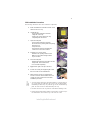
A. Read and follow the instructions shown on the
sticker on the CPU cap.
B. Unload the cap
· Use thumb & forefinger to hold the
lifting tab of the cap.
· Lift the cap up and remove the cap
completely from the socket.
C. Open the load plate
· Use thumb & forefinger to hold the
hook of the lever, pushing down and pulling
aside unlock it.
· Lift up the lever.
· Use thumb to open the load plate. Be
careful not to touch the contacts.
D. Install the CPU on the socket
· Orientate CPU package to the socket.
Make sure you match triangle marker
to pin 1 location.
E. Close the load plate
· Slightly push down the load plate onto the
tongue side, and hook the lever.
· CPU is locked completely.
F. Apply thermal grease on top of the CPU.
G. Fasten the cooling fan supporting base onto
the CPU socket on the motherboard.
H. Make sure the CPU fan is plugged to the
CPU fan connector. Please refer to the CPU
cooling fan user’s manual for more detail
installation procedure.
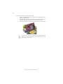
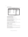
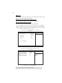
CPU Installation Procedure
The following illustration shows CPU installation components.
1. To achieve better airflow rates and heat dissipation, we suggest that you
use a high quality fan with 3800 rpm at least. CPU fan and heatsink
installation procedures may vary with the type of CPU fan/heatsink sup
plied. The form and size of fan/heatsink may also vary.
2. DO NOT remove the CPU cap from the socket before installing a CPU.
3. Return Material Authorization (RMA) requests will be accepted only if
the motherboard comes with the cap on the LGA775 socket.

12
Installing the Motherboard
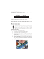
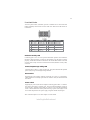
Installing Memory Modules
This motherboard accomodates four memory modules. It can support four 240-pin
DDR2 800/667. The total memory capacity is 16 GB.
You must install at least one module in any of the four slots. Each module can be
installed with 4 GB of memory; total memory capacity is 16 GB.
DDR2 SDRAM memory module table
DDR2 800 400 MHz
Memory module Memory Bus
DDR2 667 333 MHz
Do not remove any memory module from its antistatic packaging
until you are ready to install it on the motherboard. Handle the
modules only by their edges. Do not touch the components or metal
parts. Always wear a grounding strap when you handle the modules.
Installation Procedure
Refer to the following to install the memory modules.
1 This motherboard supports unbuffered DDR2 SDRAM .
2 Push the latches on each side of the DIMM slot down.
3 Align the memory module with the slot. The DIMM slots are keyed with
notches and the DIMMs are keyed with cutouts so that they can only be
installed correctly.
4 Check that the cutouts on the DIMM module edge connector match the
notches in the DIMM slot.
5 Install the DIMM module into the slot and press it firmly down until it
seats correctly. The slot latches are levered upwards and latch on to
the edges of the DIMM.
6 Install any remaining DIMM modules.
The four DDR2 memory sockets (DIMM1, DIMM2, DIMM3, DIMM4) are divided
into two channels and each channel has two memory sockets as following:
ff
Channel 0: DIMM1, DIMM2
ff
Channel 1: DIMM3, DIMM4

13
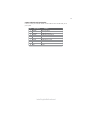
Installing the Motherboard
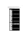
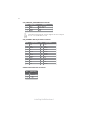
Table A: DDR2 (memory module) QVL (Qualified Vendor List)
The following DDR2 800/667 memory modules and combination have been tested
and qualified for use with this motherboard.
Type Size Vendor Module Name
Infineon HYS64T325001HU-3-A HYB18T256
256 MB
Ramaxel 5NB31 D9DCG
A-DATA AD29608A88-3EG
A-DATA M2OAD5G3H3166I1C52
Apacer 78.91G92.9K5
APOGEE AU51082-667P005
CORSAIR Corsair K4T5108QC
CORSAIR 64M8CFE PS1000545
CORSAIR VALUESELECT 32M8CEC
GEIL GL2L64M088BA18W
Infinity 0547W64M8 PC5300
Micron MT4HTF6464AY-667E1
PSC AL6E8E63J-6E1
Ramaxel 5LB31 D9DCL
SAMSUNG K4T51083QC
SyncMAX 04400WB01 R050008A
TwinMOS TMM6208G8M30B
TwinMOS 8D23JK-TT
Transcend SEL520ZCE6 K4T51083QC
512 MB
Transcend JetRam J12Q3AB-6
APACER Elpida 1GB AM4B5708GEWS7E-0637F
APACER AM4B5708GQJS7E0631F
Apacer 78.01G9O.9K5
A-DATA M2OAD5G3I4176I1C52
APOGEE AU1G082-667P005
Infineon HYB18T512800BF3S
Infineon Aeneon AET93E30RB-0650 1GB
Micron MT8HTF12864AY-667E1
PSC AL7E8E63B-6E1T
PSC AL7E8F63J-6E1
PSC AL7E8F73C-6E1
1 GB
Twinmos 8D23KK-TT
Aeneon AET860UD00-30DB08X
Apacer 78.A1G9O.9K4
Hynix HYMP125U64AP8-Y5-AB-A
LeadMax LeadMax LD5PS1G831
PSC AL8E8F73C-6E1
DDR2 667
2 GB
Qimonda HYS64T256020EU-3S- C2
A-DATA AD29608A8A-25EG
A-DATA M2OAD6G3H3160I1E53
Elpida
(Kingston)
E5108AJBG-8E-E
Infineon
HYS64T64020HU-2.5-A HYB18T256
800AF25
Infinity 04751208CZ5U2D
Kingston KHX6400D2ULK2
Kingston KHX6400D2ULK2/1G
Kingston KVR800D2N5/512
Micron 6WD22 D9GKX
Micron MT8HTF6464AY-80ED4
512 MB
Sync MAX U538H8G090HL
APACER AM4B5708BPJS8E0634E
APACER AM4B5708JQJS8E0749D
APACER AM4B5808CQJS8E0749D
Apacer 78.01GA0.9K5
A-DATA VD29608A8D-25EG-E0722
Aeneon AET760UD00-25DC08X
CORSAIR CM2X1024-6400
CORSAIR CM2X1024-6400PRO
Geil GL2L64M088BA18H
Hexon NP18T648512F-2.5
DDR2 800
1 GB
Infinity 04701G16CZ5U2G

14
Installing the Motherboard
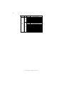
Type Size Vendor Module Name
NPC NCPT7AUDR-25M48
Kingston KHX6400D2ULK2/2G
Kingston KVR800D2N5/1G
Ramaxel E5108AHSE-8E-E 0705098L1
Samsung ZCE7 K4T510830E
Transcend TQ123PGF8T0709
1 GB
UMAX U2S12D30TP-8E
Aeneon AET03R25DC 0732
Aeneon AET860UD00-25DC08X
Apacer AM4B5808CQJS8E 0747D
Apacer 78.A1GA0.9K4
A-DATA RED A-DATA M2OMI6H3J4720L1C5Z
CORSAIR CM2X2048-6400C5
Micron 7QEIID9HNP
Micron MT16HTF25664AY-800E1
PSC A3R1GE3CFF 734MAAOE
PSC AL8E8F73C-8E1
Qimonda HYB18T1G800C2F-25F 0744
Qimonda HYS64T256020EU-25F-C2
DDR2 800
2 GB
Samsung HCF7 K4T1G084QQ
Page is loading ...
Page is loading ...
Page is loading ...
Page is loading ...
Page is loading ...
Page is loading ...
Page is loading ...
Page is loading ...
Page is loading ...
Page is loading ...
Page is loading ...
Page is loading ...
Page is loading ...
Page is loading ...
Page is loading ...
Page is loading ...
Page is loading ...
Page is loading ...
Page is loading ...
Page is loading ...
Page is loading ...
Page is loading ...
Page is loading ...
Page is loading ...
Page is loading ...
Page is loading ...
Page is loading ...
Page is loading ...
Page is loading ...
Page is loading ...
Page is loading ...
Page is loading ...
Page is loading ...
Page is loading ...
Page is loading ...
Page is loading ...
Page is loading ...
Page is loading ...
-
 1
1
-
 2
2
-
 3
3
-
 4
4
-
 5
5
-
 6
6
-
 7
7
-
 8
8
-
 9
9
-
 10
10
-
 11
11
-
 12
12
-
 13
13
-
 14
14
-
 15
15
-
 16
16
-
 17
17
-
 18
18
-
 19
19
-
 20
20
-
 21
21
-
 22
22
-
 23
23
-
 24
24
-
 25
25
-
 26
26
-
 27
27
-
 28
28
-
 29
29
-
 30
30
-
 31
31
-
 32
32
-
 33
33
-
 34
34
-
 35
35
-
 36
36
-
 37
37
-
 38
38
-
 39
39
-
 40
40
-
 41
41
-
 42
42
-
 43
43
-
 44
44
-
 45
45
-
 46
46
-
 47
47
-
 48
48
-
 49
49
-
 50
50
-
 51
51
-
 52
52
-
 53
53
-
 54
54
-
 55
55
-
 56
56
-
 57
57
-
 58
58


Ask a question and I''ll find the answer in the document
Finding information in a document is now easier with AI