Page is loading ...

Repair-Parts
Tandem Supply
Systems
For use with non-heated bulk supply of medium to high viscosity sealants and adhesive
materials. For professional use only.
Not approved for use in European explosive atmosphere locations.
125 psi (0.9 MPa, 9 bar) Maximum Air Inlet Pressure - S20 3 in. rams
150 psi (1.0 MPa, 10 bar) Maximum Air Inlet Pressure - D60 and D200 3 in. rams
125 psi (0.9 MPa, 9 bar) Maximum Air Inlet Pressure - D200S 6.5 in. rams
The Graco Control Architecture Electric Components are Listed in Intertek’s Directory of Listed Products.
Important Safety Instructions
Read all warnings and instructions in this manual.
Save these instructions.
TI10865A
D200 Rams with Electronic
Crossover Shown
313529J
EN

2 313529J
Contents
Related Manuals . . . . . . . . . . . . . . . . . . . . . . . . . . . 3
Models . . . . . . . . . . . . . . . . . . . . . . . . . . . . . . . . . . . 4
Warnings . . . . . . . . . . . . . . . . . . . . . . . . . . . . . . . . . 8
Troubleshooting . . . . . . . . . . . . . . . . . . . . . . . . . . . 10
Selector Switch . . . . . . . . . . . . . . . . . . . . . . . . . 12
Repair . . . . . . . . . . . . . . . . . . . . . . . . . . . . . . . . . . . 13
Pressure Relief Procedure . . . . . . . . . . . . . . . . 13
Ram Repair . . . . . . . . . . . . . . . . . . . . . . . . . . . . 13
Pump Repair . . . . . . . . . . . . . . . . . . . . . . . . . . . 13
Crossover Schematics . . . . . . . . . . . . . . . . . . . 13
Electronic Crossover Schematic . . . . . . . . . . . . . 14
Pneumatic Crossover Schematic . . . . . . . . . . . . . 15
Parts . . . . . . . . . . . . . . . . . . . . . . . . . . . . . . . . . . . . 17
Electronic Crossover Kits, with display . . . . . . . 19
Power Supply Detail . . . . . . . . . . . . . . . . . . . . . 22
Electronic Crossover Kits, without display . . . . . 23
Pneumatic Crossover Kits . . . . . . . . . . . . . . . . . 25
Pneumatic Crossover Kits (continued) . . . . . . . 26
Fluid Filter Kit . . . . . . . . . . . . . . . . . . . . . . . . . . 28
Pump Outlet Check Valve Kits . . . . . . . . . . . . . 29
Depressurization Kits . . . . . . . . . . . . . . . . . . . . 30
Accessories . . . . . . . . . . . . . . . . . . . . . . . . . . . . . . 32
Communications Gateway Module . . . . . . . . . . 32
Pressure Sensor Accessories . . . . . . . . . . . . . . 32
Technical Data . . . . . . . . . . . . . . . . . . . . . . . . . . . . 33
Graco Standard Warranty . . . . . . . . . . . . . . . . . . . 34
Graco Information . . . . . . . . . . . . . . . . . . . . . . . . 34

Related Manuals
313529J 3
Related Manuals
Component Manuals in U.S. English:
Manual Description
313528 Tandem Supply Systems Operation
313526 Supply Systems Operation
313527 Supply Systems Repair-Parts
312375
Check-Mate
®
Displacement Pumps
Instructions-Parts
312376
Check-Mate
®
Pump Packages
Instruction-Parts
311827
Dura-Flo
™
Displacement Pumps (145cc,
180cc, 220cc, 290cc) Instructions-Parts
Manual
311825
Dura-Flo
™
Displacement Pumps (430cc,
580cc) Instructions-Parts Manual
311717
Carbon Steel Displacement Pump
(1000cc) Instructions-Parts Manual
311828
Dura-Flo
™
Pump Packages (145cc,
180cc, 220cc, 290cc) Instructions-Parts
Manual
311826
Dura-Flo
™
Pump Packages (430cc,
580cc) Instructions-Parts Manual
311833
Two-Ball NXT
™
Pump Packages (1000cc)
Instructions-Parts Manual
312889
60 cc Check-Mate Displacement Pump
Repair Parts Manual
312467
100 cc Check-Mate Displacement Pump
Repair Parts Manual
312468
200 cc Check-Mate Displacement Pump
Repair Parts Manual
312469
250 cc Check-Mate Displacement Pump
Repair Parts Manual
312470
500 cc Check-Mate Displacement Pump
Repair Parts Manual
311238
NXT
™
Air Motor (Nxxxxx models)
Instructions-Parts
312796
NXT
™
Air Motor (Mxxxxx models)
Instructions-Parts
308213 Premier
®
Air Motor Instructions-Parts
312374 Air Controls Instructions-Parts
312491 Pump Fluid Purge Kit
312492 Drum Roller Kit Instruction
312493 Light Tower Kit Instruction
312864
Communications Gateway Module,
Instructions-Parts
313138
Supply System Communications Gateway
Module Installation Kit, Instructions-Parts
406681 Platen Cover Kit

Models
4 313529J
Models
Check the identification plate (ID) for the 6-digit part number of your tandem sys-
tem. Use the following matrix to define the construction of your system, based on
the six digits. For example, Tandem Part No. TC2414 represents a Check-Mate
tandem system (TC), pump (24), crossover option (1), and platen/ram option (4).
NOTE:
Systems with the TD as the first and second digits are Dura-Flo tandem systems.
Some configurations in the following matrix cannot be built. See the Product
Selection Guide for available systems.
To order replacement parts, see on page 16. The digits in the matrix do not cor-
respond to the Ref. Nos. in the Parts drawings and lists.
All supply systems with DataTrak and 24 Vdc or 100-240 Vac power supplies are ETL approved.
ID
TI11157A
TC 24 1 4
First and
Second Digit
Third and
Fourth Digit Fifth Digit Sixth Digit
Pump Code
Crossover Options
Platen/Ram
Options
Electronic
Crossover
(Smart
Motors
only)
Pneumatic
Crossover
(Standard
Motors
only)
Fluid
Filter
Depressurize/
Recirculate Valve
Material
Ram Size
See Table 1
for Selections
Carbon
Steel SST
TC
(Tandem
System with
Check-Mate
displacement
pump)
TD
(Tandem
System with
Dura-Flo dis-
placement
pump)
(See Table 2
for 2-digit
Check-Mate
pump code)
(See Table 3
for 2-digit
Dura-
Flo pump
code)
1
✔
✔✔
n/a
2
✔✔✔
n/a
3
✔✔
n/a
4
✔✔
n/a
5
✔✔
n/a
6
✔
n/a
7
✔
S20, D60,
D200,
(3 in.)
8
✔
D200S,
(6.5 in.)
2ECOGNIZED#OMPONENT
#ERTIFIEDTO#!.#3!#3!#.O
#ONFORMSTO5,
#-

Models
313529J 5
Table 1: Platen/Ram Options
Sixth
Digit Platen Size Platen Style
Platen
Material
Seal Material Ram Size Voltage
2 20 L (5 Gal) Flat, Single Wiper CS Polyurethane S20, 3 in. none
3 20 L (5 Gal) Flat, Single Wiper SST PTFE-Coated Nitrile S20, 3 in none
7 20 L (5 Gal) Flat, Dual Wiper CS Polyurethane D60, 3 in. none
8 20 L (5 Gal) Flat, Dual Wiper CS Polyurethane D60, 3 in. 120 Vdc
9 20 L (5 Gal) Flat, Dual Wiper CS Polyurethane D60, 3 in. 24 Vdc
0 30 L (8 Gal) Flat, Single Wiper SST PTFE-Coated Nitrile D60, 3 in. none
D 30 L (8 Gal) Flat, Single Wiper SST PTFE-Coated Nitrile D60, 3 in. 120 Vdc
E 30 L (8 Gal) Flat, Single Wiper SST PTFE-Coated Nitrile D60, 3 in. 24 Vdc
K 30 L (8 Gal) Flat, Dual Wiper CS Polyurethane D60, 3 in. none
N 30 L (8 Gal) Flat, Dual Wiper CS Polyurethane D60, 3 in. 120 Vdc
P 30 L (8 Gal) Flat, Dual Wiper CS Polyurethane D60, 3 in. 24 Vdc
U 60 L (16 Gal) Flat, Single Wiper SST PTFE-Coated Nitrile D60, 3 in. none
V 60 L (16 Gal) Flat, Single Wiper SST PTFE-Coated Nitrile D60, 3 in. 120 Vdc
W 60 L (16 Gal) Flat, Single Wiper SST PTFE-Coated Nitrile D60, 3 in. 24 Vdc
X 60 L (16 Gal) Flat, Dual Wiper CS Polyurethane D60, 3 in. none
Y 60 L (16 Gal) Flat, Dual Wiper CS Polyurethane D60, 3 in. 120 Vdc
Z 60 L (16 Gal) Flat, Dual Wiper CS Polyurethane D60, 3 in. 24 Vdc
4 115L (30 Gal) D Style CS EPDM D200, 3 in. none
1 20 L (5 Gal) Flat, Single Wiper SST PTFE-Coated Nitrile D200, 3 in. none
6 20 L (5 Gal) Flat, Dual Wiper CS Polyurethane D200, 3 in none
A 200 L (55 Gal) Dual O-ring AL PTFE-Coated EPDM D200, 3 in. none
B 200 L (55 Gal) Dual O-ring AL PTFE-Coated EPDM D200, 3 in. 120 Vdc
C 200 L (55 Gal) Dual O-ring AL PTFE-Coated EPDM D200, 3 in. 24 Vdc
F 200 L (55 Gal) Dual O-ring AL PTFE-Coated EPDM D200S, 6.5 in. none
G 200 L (55 Gal) Dual O-ring AL PTFE-Coated EPDM D200S, 6.5 in. 120 Vdc
H 200 L (55 Gal) Dual O-ring AL PTFE-Coated EPDM D200S, 6.5 in. 24 Vdc
J 200 L (55 Gal) Dual O-ring AL EPDM D200, 3 in. none
L 200 L (55 Gal) Dual O-ring AL EPDM D200, 3 in. 120 Vdc
M 200 L (55 Gal) Dual O-ring AL EPDM D200, 3 in. 24 Vdc
R 200 L (55 Gal) Dual O-ring AL EPDM D200S, 6.5 in. none
S 200 L (55 Gal) Dual O-ring AL EPDM D200S, 6.5 in. 120 Vdc
T 200 L (55 Gal) Dual O-ring AL EPDM D200S, 6.5 in. 24 Vdc

Models
6 313529J
Pump
Code
Pump Part No.
(see manual
312376)
NXT 200/CM 60
4A P05LCS
4B P05LCM
4C P05LSS
4F P05LSM
NXT 400/CM 60
6A P11LCS
6B P11LCM
6C P11LSS
6F P11LSM
6G P11RCS
6H P11RCM
6J P11RSS
6K P11RSM
61 P11SCS
62 P11SCM
63 P11SSS
64 P11SSM
NXT 700/CM 60
7A P20LCS
7B P20LCM
7C P20LSS
7F P20LSM
7G P20RCS
7H P20RCM
7J P20RSS
7K P20RSM
71 P20SCS
72 P20SCM
73 P20SSS
74 P20SSM
NXT 1200/CM 60
8A P38LCS
8B P38LCM
8C P38LSS
8F P38LSM
8G P38RCS
8H P38RCM
8J P38RSS
8K P38RSM
81 P38SCS
82 P38SCM
83 P38SSS
84 P38SSM
NXT 1800/CM 60
9A P61LCS
9B P61LCM
9C P61LSS
9F P61LSM
9G P61RCS
9H P61RCM
9J P61RSS
9K P61RSM
91 P61SCS
92 P61SCM
93 P61SSS
94 P61SSM
NXT 2200/CM 100
11 P40LCS
12 P40LCM
1F P40LSS
1G P40LSM
13 P40RCS
14 P40RCM
1H P40RSS
1J P40RSM
10 P40SSS
1A P40SSM
19 P40SCS
NXT 3400/CM 100
15 P63LCS
16 P63LCM
1T P63LSS
1U P63LSM
17 P63RCS
18 P63RCM
1W P63RSS
1Y P63RSM
1B P63SSS
1C P63SSM
Pump
Code
Pump Part No.
(see manual
312376)
NXT 2200/CM 200
21 P23LCS
22 P23LCM
23 P23RCS
24 P23RCM
25 P23LSS
26 P23LSM
27 P23RSS
28 P23RSM
NXT 3400/CM 200
29 P36LCS
2A P36LCM
2B P36RCS
2C P36RCM
2F P36LSS
2G P36LSM
2H P36RSS
2J P36RSM
NXT 6500/CM 200
2L P68LCS
2M P68LCM
2R P68RCS
2S P68RCM
2T P68LSS
2U P68LSM
2W P68RSS
2Y P68RSM
20 P68SCS
NXT 3400/CM 250
31 P29LCS
32 P29LCM
33 P29RCS
34 P29RCM
35 P29LSS
36 P29LSM
37 P29RSS
38 P29RSM
Pump
Code
Pump Part No.
(see manual
312376)
NXT 6500/CM 250
39 P55LCS
3A P55LCM
3B P55RCS
3C P55RCM
3F P55LSS
3G P55LSM
3H P55RSS
3J P55RSM
Premier/CM 250
3L P82LCS
3M P82LCM
3R P82LSS
3S P82LSM
NXT 3400/CM 500
51 P14LCS
52 P14LCM
53 P14RCS
54 P14RCM
55 P14LSS
56 P14LSM
57 P14RSS
58 P14RSM
NXT 6500/CM 500
59 P26LCS
5A P26LCM
5B P26RCS
5C P26RCM
5F P26LSS
5G P26LSM
5H P26RSS
5J P26RSM
Premier/CM 500
5L P39LCS
5M P39LCM
5R P39LSS
5S P39LSM
No Pump
NN
Pump
Code
Pump Part No.
(see manual
312376)
Table 2: Check-Mate Pump Identification Code/Part No. Index

Models
313529J 7
Pump
Code
Pump Part No.
(see manual
311828)
NXT 2200/DF 145SS
A1 P31LSS
A2 P31LSM
A3 P31HSS
A4 P31HSM
NXT 3400/DF 145SS
B1 P46LSS
B2 P46LSM
B3 P46HSS
B4 P46HSM
NXT 3400/DF 180SS
B5 P41LSS
B6 P41LSM
B7 P41HSS
B8 P41HSM
NXT 3400/DF 220SS
C1 P30LSS
C2 P30LSM
C3 P30HSS
C4 P30HSM
NXT 6500/DF 220SS
CA P57LSS
CB P57LSM
CC P57HSS
CD P57HSM
NXT 6500/DF 290SS
D1 P45LSS
D2 P45LSM
D3 P45HSS
D4 P45HSM
Premier/DF 290SS
DL P67LSS
DM P67LSM
DR P67HSS
DS P67HSM
Pump
Code
Pump Part No.
(see manual
311826)
NXT 3400/DF 430CS
E1 P15LCS
E2 P15LCM
E3 P15HCS
E4 P15HCM
NXT 3400/DF 430SS
E5 P15LSS
E6 P15LSM
E7 P15HSS
E8 P15HSM
NXT 6500/DF 430CS
E9 P32LCS
EA P32LCM
EB P32HCS
EC P32HCM
NXT 6500/DF 430SS
EF P32LSS
EG P32LSM
EH P32HSS
EJ P32HSM
Premier/DF 430
EL P44LSS
EM P44LSM
ER P44LCS
ES P44LCM
NXT 3400/DF 580CS
F1 P12LCS
F2 P12LCM
F3 P12HCS
F4 P12HCM
NXT 3400/DF 580SS
F5 P12LSS
F6 P12LSM
F7 P12HSS
F8 P12HSM
Pump
Code
Pump Part No.
(see manual
311826)
NXT 6500/DF 580CS
F9 P22LCS
FA P22LCM
FB P22HCS
FC P22HCM
NXT 6500/DF 580SS
FF P22LSS
FG P22LSM
FH P22HSS
FJ P22HSM
Premier/DF 580CS
FL P34LSS
FM P34LSM
FR P34LCS
FS P34LCM
Pump
Code
Pump Part No.
(see manual
311833)
NXT 3400/DF 1000CS
G1 P06LCS
G2 P06LCM
G3 P06HCS
G4 P06HCM
NXT 3400/DF 1000SS
G5 P06LSS
G6 P06LSM
G7 P06HSS
G8 P06HSM
NXT 6500/DF 1000CS
G9 P10LCS
GA P10LCM
GB P10HCS
0C P10HCM
NXT 6500/DF 1000SS
GF P10LSS
GG P10LSM
GH P10HSS
GJ P10HSM
Premier/DF 1000
GL NR
GM NR
GR NR
GS NR
Table 3: Dura-Flo Pump Identification Code/Part No. Index
NR = Not released

Warnings
8 313529J
Warnings
The following warnings are for the setup, use, grounding, maintenance, and repair of this equipment. The exclama-
tion point symbol alerts you to a general warning and the hazard symbol refers to procedure-specific risk. Refer back
to these warnings. Additional, product-specific warnings may be found throughout the body of this manual where
applicable.
WARNING
SKIN INJECTION HAZARD
High-pressure fluid from gun, hose leaks, or ruptured components will pierce skin. This may look like just
a cut, but it is a serious injury that can result in amputation. Get immediate surgical treatment.
• Do not point gun at anyone or at any part of the body.
• Do not put your hand over the spray tip.
• Do not stop or deflect leaks with your hand, body, glove, or rag.
• Do not spray without tip guard and trigger guard installed.
• Engage trigger lock when not spraying.
• Follow Pressure Relief Procedure in this manual, when you stop spraying and before cleaning,
checking, or servicing equipment.
MOVING PARTS HAZARD
Moving parts can pinch or amputate fingers and other body parts.
• Keep clear of moving parts.
• Do not operate equipment with protective guards or covers removed.
• Pressurized equipment can start without warning. Before checking, moving, or servicing equipment,
follow the Pressure Relief Procedure in this manual. Disconnect power or air supply.
FIRE AND EXPLOSION HAZARD
Flammable fumes, such as solvent and paint fumes, in work area can ignite or explode. To help prevent
fire and explosion:
• Use equipment only in well ventilated area.
• Eliminate all ignition sources; such as pilot lights, cigarettes, portable electric lamps, and plastic drop
cloths (potential static arc).
• Keep work area free of debris, including solvent, rags and gasoline.
• Do not plug or unplug power cords, or turn power or light switches on or off when flammable fumes
are present.
• Ground all equipment in the work area. See Grounding instructions.
• Use only grounded hoses.
• Hold gun firmly to side of grounded pail when triggering into pail.
• If there is static sparking or you feel a shock, stop operation immediately. Do not use equipment
until you identify and correct the problem.
• Keep a working fire extinguisher in the work area.

Warnings
313529J 9
WARNINGWARNINGWARNING
WARNING
EQUIPMENT MISUSE HAZARD
Misuse can cause death or serious injury.
• Do not operate the unit when fatigued or under the influence of drugs or alcohol.
• Do not exceed the maximum working pressure or temperature rating of the lowest rated system
component. See Technical Data in all equipment manuals.
• Use fluids and solvents that are compatible with equipment wetted parts. See Technical Data in all
equipment manuals. Read fluid and solvent manufacturer’s warnings. For complete information
about your material, request MSDS forms from distributor or retailer.
• Check equipment daily. Repair or replace worn or damaged parts immediately with genuine manu-
facturer’s replacement parts only.
• Do not alter or modify equipment.
• Use equipment only for its intended purpose. Call your distributor for information.
• Route hoses and cables away from traffic areas, sharp edges, moving parts, and hot surfaces.
• Do not kink or over bend hoses or use hoses to pull equipment.
• Keep children and animals away from work area.
• Comply with all applicable safety regulations.
ELECTRIC SHOCK HAZARD
Improper grounding, setup, or usage of the system can cause electric shock.
• Turn off and disconnect power cord before servicing equipment.
• Use only grounded electrical outlets.
• Use only 3-wire extension cords.
• Ensure ground prongs are intact on sprayer and extension cords.
• Do not expose to rain. Store indoors.
SPLATTER HAZARD
During blowoff of platen splatter may occur.
• Use minimum drum removal air pressure.
TOXIC FLUID OR FUMES HAZARD
Toxic fluids or fumes can cause serious injury or death if splashed in the eyes or on skin, inhaled, or
swallowed.
• Read MSDS’s to know the specific hazards of the fluids you are using.
• Store hazardous fluid in approved containers, and dispose of it according to applicable guidelines.
• Always wear impervious gloves when spraying or cleaning equipment.
PERSONAL PROTECTIVE EQUIPMENT
You must wear appropriate protective equipment when operating, servicing, or when in the operating
area of the equipment to help protect you from serious injury, including eye injury, inhalation of toxic
fumes, burns, and hearing loss. This equipment includes but is not limited to:
• Protective eyewear
• Clothing and respirator as recommended by the fluid and solvent manufacturer
•Gloves
• Hearing protection

Troubleshooting
10 313529J
Troubleshooting
NOTE: Refer to the Supply System Repair-Parts
manual for specific ram troubleshooting. Refer to
the Check-Mate Pump Packages manual for pump
troubleshooting.
1. Follow Pressure Relief Procedure, page 13, before
disassembling any part of the supply system.
2. Disconnect power before repairing the supply sys-
tem.
3. Check all possible problems and causes before dis-
assembling the supply system.
Problem Cause Verification Solution
No power. Customer supplied main
circuit breaker tripped.
Measure voltage across
disconnect switch; voltage
should measure between
190 and 250 Vac.
Determine cause of the
tripped circuit breaker.
Then repair fault and reset
main circuit breaker.
No graphics on screen. No graphics are shown on
display screen.
Verify green LED on bottom
of display is illuminated.
If green LED is not illumi-
nated:
1. Check for DC power at
display. Replace faulty
cable/component.
2. Replace faulty display
module.
If green LED is illuminated,
check red LED. If red LED
is illuminated, replace dis-
play module.
Backlight does not power
up.
Can see display, but back-
light is not illuminated when
a button is pressed.
Replace display module.

Troubleshooting
313529J 11
Missing module. Modules not on network. Verify attached modules
through Advanced Setup
screens 4 and 5.
Enter Setup screen and
scroll to Advanced Setup
screens 4 and 5. These
screens lists all compo-
nents corresponding soft-
ware revision number on
network.
Cable disconnected. Verify all green LEDs are
illuminated and yellow
LEDs are flashing.
Reconnect/replace faulty
cable.
Module with wrong selec-
tor switch setting.
Verify selector switch is set
correctly.
1. Remove power from
unit.
2. Remove access cover
and visually check
rotary switch setting.
3. If incorrect, set to cor-
rect setting. See Selec-
tor Switch, page 12,
for selector switch loca-
tions.
4. Replace access cover.
Does not crossover. Alternate ram has an empty
sensor activated.
Verify ram has material. Replace empty drum.
Alternate pump is not
primed.
Verify alternate ram is
ready to run.
Prime pump.
Alternate pump has an
active alarm.
See Alarm Codes and
Troubleshooting in the
Tandem Supply Systems
Operation manual.
See Alarm Codes and
Troubleshooting in the
Tandem Supply Systems
Operation manual.
Problem Cause Verification Solution

Troubleshooting
12 313529J
Selector Switch
Ensure the selector switch (inside the fluid control mod-
ule) is set correctly for each ram.
1. Turn power off.
2. Remove access cover (D).
3. For ram A, ensure the selector switch (S) is set to
“A”. If it is not, use a flat head screwdriver to adjust
the switch to “A”.
4. For ram B, ensure the selector switch (S) is set to
“B”. If it is not, use a flat head screwdriver to adjust
the switch to “B”.
5. Replace access cover.
6. Turn power on.
F
IG. 1:
TI12334a
D
F
IG. 2:
S

Repair
313529J 13
Repair
Pressure Relief Procedure
1. Lock the gun/valve trigger.
2. Press On/Off key . If system is On, display will
highlight . Select to turn off.
3. Turn off the air motor slider valve (BF) on both ram A
and B.
4. On both ram A and B, turn off the main air slider
valve (BA). Set the ram director valve (BC) to the
down position. The ram will slowly drop.
5. Unlock the gun/valve trigger.
6. Hold a metal part of the gun/valve firmly to the side
of a grounded metal pail, and trigger the gun/valve
to relieve pressure.
7. Lock the gun/valve trigger.
8. On both ram A and B, open the drain valve and/or
the pump bleed port. Have a container ready to
catch the drainage.
If you suspect that the spray tip/nozzle or hose is com-
pletely clogged, or that pressure has not been fully
relieved after following the steps above, very slowly
loosen the tip guard retaining nut or hose end coupling
and relieve pressure gradually, then loosen completely.
Now clear the tip/nozzle or hose.
Ram Repair
See manual 313527 for ram and platen repair proce-
dures and replacement parts.
Pump Repair
See pump manuals for pump repair procedures and
replacement parts.
See manual 311238 (Nxxxxx NXT models), 312796
(Mxxxxx NXT models), or 308213 (Premier) for air motor
repair procedures and replacement parts.
Crossover Schematics
See page 14 for a schematic of electronic crossover
systems and page 15 for a schematic of pneumatic
crossover systems.
FIG. 3: System Function Screen
FIG. 4. Integrated Air Controls
BA
BB
BC
BG
BE
BF
TI10438A

Electronic Crossover Schematic
14 313529J
Electronic Crossover Schematic
Power (1)
Low Sensor (2)
Common (3)
1
(2) N/C
(3) Motor Reed Up
(5) Motor Reed Com
5
(7) Linear Com
-24Vdc (3)
+24Vdc (2)
CAN_H (4)
CAN_L (5)
SHLD (1)
-24Vdc (3)
+24Vdc (2)
CAN_H (4)
CAN_L (5)
SHLD (1)
-24Vdc (3)
+24Vdc (2)
CAN_H (4)
CAN_L (5)
SHLD (1)
-24Vdc (3)
+24Vdc (2)
CAN_H (4)
CAN_L (5)
SHLD (1)
M
E
M
B
R
A
N
E
S
W
I
T
C
H
DISPLAY
MODULE
FLUID
CONTROL
MODULE
RAM A
-24Vdc (3)
+24Vdc (2)
CAN_H (4)
CAN_L (5)
SHLD (1)
-24Vdc (3)
+24Vdc (2)
CAN_H (4)
CAN_L (5)
SHLD (1)
FLUID
CONTROL
MODULE
RAM B
+24Vdc POWER SUPPLY
Gracp P/N 15M293
-24Vdc
+24Vdc
SHLD
L
N
Light Tower
Graco P/N 15X472
Top Switch 1
Top Switch 2
Bottom Switch 1
Bottom Switch 2
(1) Power
(4) SIGNAL
(3) COM
(1) Solenoid signal
(2) Solenoid RTN
Cable 8 Pin
Graco P/N 15Y051
F
M
AIR SOLENOID
Graco P/N 121235
(1) Linear Input
(4) Motor Reed Down
(6) Linear Power
(8) Drain
Empty Sensor (4)
Air Solenoid (5)
Cable Splitter
Graco P/N 15X968
Cable, CAN 15m
Graco P/N 121228
D
I
S
P
L
A
Y
MF
Sensor Reed Switch
Graco P/N 119700
F
(1)
(3)
(4)
(1)
(2)
(3)
(4)
(1)
(2)
(3)
(4)
(1)
(2)
(3)
(4)
(1)
(2)
(3)
(4)
Cable, CAN 0.6m
Graco P/N 121227
M
(1)
(2)
(3)
(4)
DRUM EMPTY
Graco P/N 122716
F
(1)
(2)
DRUM LOW
Graco P/N 122716
Unused (1)
Amber (2)
Common (3)
2
Green (4)
Red (5)
(5)
(1) Unused
(2) Amber
(3) Common
(4) Green
(5) Red
Fluid Solenoid
Graco P/N 15M574
M
(1)
(2)
(3)
(4)
Unused (1)
Drain (2)
Common (3)
3
Signal (4)
(1) Signal
(2) Common
(GND) Unused
M
(1)
(2)
(3)
(4)
(5)
F
(1)
(2)
(3)
Wire Harness
Graco P/N 15Y047
M
(1)
(2)
(3)
(4)
(1) Power
(2) Filter Inlet Press.
(3) Common
7
(4) Filter Outlet Press.
(5) Drain
(1)
(2)
(3)
(4)
(5)
Fluid Pressure Sensor
Graco P/N 121175
(1)
(2)
(3)
(4)
Fluid Pressure Sensor
Graco P/N 121175
Cable Splitter
Graco P/N 15Y037
MF
(1)
(2)
(3)
(4)
(1)
(2)
(3)
(4)
(5) (5)
Power (1)
Unused (2)
Common (3)
Press Signal (4)
Power (1)
Unused (2)
Common (3)
Press Signal (4)
M
(1)
(2)
(3)
(4)
(5)
(5)
(6)
(7)
(8)
(5)
(6)
(7)
(8)
M
(1)
(2)
(3)
(4)
(5)
(6)
(7)
(8)
Motor Pigtail
Graco P/N 15X619
Power (1)
Low Sensor (2)
Common (3)
1
Empty Sensor (4)
Air Solenoid (5)
Cable Splitter
Graco P/N 15X968
M
(1)
(2)
(3)
(4)
(5)
M
(1)
(2)
(3)
(4)
Unused (1)
Drain (2)
Common (3)
3
Wire Harness
Graco P/N 15Y047
Top Switch (1)
Top Switch (2)
Bottom Switch (1)
Bottom Switch (2)
Cable 8 Pin
Graco P/N 15Y051
FM
MF
Sensor Reed Switch
Graco P/N 119700
(1)
(2)
(3)
(4)
(1)
(2)
(3)
(4)
(1)
(2)
(3)
(4)
(1)
(2)
(3)
(4)
M
(1)
(2)
(3)
(4)
(5)
(5)
(6)
(7)
(8)
(5)
(6)
(7)
(8)
Motor Pigtail
Graco P/N 15X619
Signal (4)
Cable 15 Meter
Graco P/N 15Y048
(2) Unused
(2)
(1) Power
(4) SIGNAL
(3) COM
(1)
(3)
(4)
(2) Unused
(2)
(1) Power
(4) SIGNAL
(3) COM
(1) Solenoid signal
(2) Solenoid RTN
AIR SOLENOID
Graco P/N 121235
F
(1)
(3)
(4)
DRUM EMPTY
Graco P/N 122716
F
(1)
(2)
DRUM LOW
Graco P/N 122716
(2) Unused
(2)
(1) Power
(4) SIGNAL
(3) COM
(1)
(3)
(4)
(2) Unused
(2)
Fluid Solenoid
Graco P/N 15M574
(1) Signal
(2) Common
(GND) Unused
F
(1)
(2)
(3)
(2) N/C
(3) Motor Reed Up
(5) Motor Reed Com
5
(7) Linear Com
(1) Linear Input
(4) Motor Reed Down
(6) Linear Power
(8) Drain
M
(1)
(2)
(3)
(4)
(5)
(6)
(7)
(8)
Cable, CAN 0.4m
Graco P/N 121226
Ferrite Bead
Graco P/N 121901
Ferrite Bead
Graco P/N 121901
Ferrite Bead
Graco P/N 121901
Ferrite Bead
Graco P/N 121901
Ferrite Bead
Graco P/N 121901
Filter Accessory Kit
Depressurization
Accessory Kit

Pneumatic Crossover Schematic
313529J 15
Pneumatic Crossover Schematic

Pneumatic Crossover Schematic
16 313529J

Parts
313529J 17
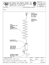
Parts
Tandem Supply System; Electronic Crossover Model Shown
TI10865A
2
3
4
5
6
7
8
9
10
11
12
2
3
4
5
6
10
11
12
Supply System A Supply System B
D200 Rams Shown

Parts
18 313529J
NOTE:
See on page 4 to identify the components included in
your Tandem Supply System.
★ Not shown.
❄ See Supply Systems Repair-Parts manual 313527 for
parts.
✠ See page 19 for parts.
† See page 23 for parts.
◆ See page 29 for parts.
❖ See page 30 for parts.
✓ See page 25 for parts.
Ref. Part Description Qty.
2 255648❄ RAM ASSEMBLY, D200, 3 in. 2
255688❄ RAM ASSEMBLY, D200s, 6.5 in. 2
257620❄ RAM ASSEMBLY, S20, 3 in. 2
257621❄ RAM ASSEMBLY, D60, 3 in. 2
3 see Table
2, page 6
PUMP, Check-Mate; see manual 312375
for parts
2
4 255662❄ PLATEN, 55 gal., o-ring, PTFE 2
255663❄ PLATEN, 55 gal., o-ring, EPDM 2
255661❄ PLATEN, 30 gal., D-style, EPDM 2
257728❄ PLATEN, 20 liter, single wiper, polyure-
thane
2
257729❄ PLATEN, 20 liter, single wiper, PTFE 2
257731❄ PLATEN, 20 liter, double wiper, polyure-
thane
2
257734❄ PLATEN, 30 liter, single wiper, PTFE 2
257736❄ PLATEN, 30 liter, double wiper, polyure-
thane
2
257738❄ PLATEN, 60 liter, single wiper, PTFE 2
257741❄ PLATEN, 60 liter, double wiper, polyure-
thane
2
5 255305❄ KIT, mounting, pump; 3 in.; 55 gal. 2
255308❄ KIT, mounting, pump; 3 in.; 20 liter and 30
gal.; for NXT 3400 and 6500 air motors
2
255309❄ KIT, mounting, pump; 3 in.; 20 liter and 30
gal.; for NXT 2200 air motors
2
255315❄ KIT, mounting, pump; 6.5 in.; 55 gal. 2
255316❄ KIT, mounting, pump; 6.5 in.; 20 liter and
30 gal.; for NXT 3400 and 6500 air motors
2
255317❄ KIT, mounting, pump; 6.5 in.; 20 liter and
30 gal.; for NXT 2200 air motors
2
256235❄ KIT, mounting, pump; 3 in.; 55 gal.; for
Dura-Flo pumps
2
257666❄ KIT, mounting, pump; S20, 3 in.; 5 gal.; for
NXT 2200 and 3400 air motors
2
257664❄ KIT, mounting, pump; S20, 3 in.; 5 gal.; for
NXT 200, 400, 700, 1200, and 1800 air
motors
2
257623❄ KIT, mounting, pump; D60, 3 in.; 5 gal.; for
NXT 2200 air motors
2
257624❄ KIT, mounting, pump; D60, 3 in.; 5 gal.; for
NXT 3400 and 6500 air motors
2
6 255392❄ KIT, mounting; for all 55 gal. and 30 gal.
platens
2
257630❄ KIT, mounting; for DuraFlo pumps to 20,
30, 60 liter platens
2
7 255706✠ KIT, electronic crossover, with display,
Vac; for 3 in. D200 and D60 Ram A
1
255759✠ KIT, electronic crossover, with display,
Vdc; for 3 in. D200 and D60 Ram A
1
255707✠ KIT, electronic crossover, with display,
Vac; for 6.5 in. D200s Ram A
1
255760✠ KIT, electronic crossover, with display,
Vdc; for 6.5 in. D200s Ram A
1
8 255708† KIT, electronic crossover, no display; for 3
in. D200 and D60 Ram B
1
255709† KIT, electronic crossover, no display; for
6.5 in. D200s Ram B
1
9 247504 KIT, fluid filter; included with electronic
crossover models only; see page 28
10 VALVE, safety relief; located out of view,
on back side of air controls
2
116643 For systems with pumps: P55xxx and
P57xxx
103347 For systems with pumps: P05xxx, P06xxx,
P10xxx, P11xxx, P12xxx, P14xxx,
P15xxx, P20xxx, P22xxx, P23xxx,
P26xxx, P29xxx, P30xxx, P31xxx,
P32xxx, P34xxx, P36xxx, P38xxx,
P39xxx, P40xxx, P41xxx, P44xxx,
P45xxx, P46xxx
120306 For systems with pumps: P61xxx, P63xxx,
and P67xxx
108124 For systems with pumps: P68xxx
110065 For systems with pumps: P82xxx
11 255452◆ KIT, pump outlet check valve; used on cst
Check-Mate 60 and 100 displacement
pumps
2
257377◆ KIT, pump outlet check valve; used on sst
Check-Mate 60 and 100 displacement
pumps
2
255453◆ KIT, pump outlet check valve; used on cst
Check-Mate 200 and 250 displacement
pumps
2
255454◆ KIT, pump outlet check valve; used on sst
Check-Mate 200 and 250 displacement
pumps
2
255455◆ KIT, pump outlet check valve; used on cst
Check-Mate 500 displacement pumps
2
255456◆ KIT, pump outlet check valve; used on sst
Check-Mate 500 displacement pumps
2
256882◆ KIT, pump outlet check valve; used on cst
Dura-Flo 430 and 580 displacement
pumps
12 255457❖ KIT, depressurization; cst; included with
electronic crossover models only
2
255458❖ KIT, depressurization; sst; included with
electronic crossover models only
2
13★ 255675✓ KIT, pneumatic crossover; for 3 in. D200
rams
1
255676✓ KIT, pneumatic crossover; for 6.5 in.
D200s rams
1
257633✓ KIT, pneumatic crossover; for S20 rams 1
257632✓ KIT, pneumatic crossover; for 3 in. D60
rams
1
Ref. Part Description Qty.

Parts
313529J 19
Electronic Crossover Kits, with display
255706, with display, Vac, for 3 in. D200 and D60 Ram A
255759, with display, Vdc, for 3 in. D200 and D60 Ram A
255707, with display, Vac, for 6.5 in. D200s Ram A
255760, with display, Vdc, for 6.5 in. D200s Ram A
114
113
116
117
109
110
r_257374_313529_4a
115 (Ref)
108
107
126
127
101
102
106
125
101
102
101
102
121
111
112
Harness (115) Detail
TI10909A_1
1
To connection 1 on fluid control module (126).
To air motor solenoid (129).
To drum empty sensor (124).
To accessory drum low sensor (if present).
1
2
4
5
2
4
5
See page 22 for
power supply detail
129
116
115 (Ref)
124
128
148
147
140
146
122
115 (Ref)

Parts
20 313529J
Electronic Crossover Kits, with display
Parts designated n/a are not available separately.
★ Not shown.
‡ D60 ram only: Position collar of actuator sensor
down, near ram weldment, with bracket pointing up.
* Requires Ref. 149 for programming.
Ref. Description
255706
(Vac, for D200
and D60 Rams;
see pages 18
and 22)
255759
(Vdc, for D200
and D60 Rams;
see pages 18
and 22)
255707
(Vac, for
D200s Ram; see
pages 18 and 22)
255760
(Vdc, for
D200s Ram; see
pages 18 and 22) Qty.
101 WASHER, lock; 1/4 100016 100016 100016 100016 15
102 SCREW, cap, socket-hd; 1/4-20 x
5/8 in. (16 mm)
101682 101682 101682 101682 15
106 COVER, shroud front, 3 in. n/a n/a 1
COVER, shroud front, 6.5 in.
n/a n/a 1
107 COVER, shroud rear, 3 in. n/a n/a 1
COVER, shroud rear, 6.5 in. n/a n/a 1
108 BRACKET, light tower, 3 in. n/a n/a 1
BRACKET, light tower, 6.5 in.
n/a n/a 1
109 CABLE, CAN, display/power sup-
ply; m x f; 0.4 m
121226 121226 121226 121226 1
110* MODULE, display 24F493 24F493 24F493 24F493 1
111 BRACKET, pivot n/a n/a n/a n/a 1
112 BRACKET, mounting, display mod-
ule
n/a n/a n/a n/a 1
113 SCREW, cap, socket-hd, 1/4-20 x
4.25 in. (108 mm)
121250 121250 121250 121250 1
114 NUT, lock, hex; 1/4-20 102040 102040 102040 102040 1
115 HARNESS, fluid control module 15X968 15X968 15X968 15X968 1
116 WASHER, plain 110755 110755 110755 110755 1
117 KNOB, display adjustment 121253 121253 121253 121253 1
121 CABLE, CAN, display/fluid control
module; fbe; 0.6 m
121227 121227 121227 121227 1
122 CABLE, M12, 8 pin, air motor reed
switch
15Y051 15Y051 15Y051 15Y051 1
124 SENSOR, inductive, low/empty 122716 122716 122716 122716 1
125 BRACKET, sensor, low/empty n/a n/a n/a n/a 1
126* MODULE, fluid control 289696 289696 289696 289696 1
127‡
ACTUATOR, sensor, low/empty;
3 in.
n/a n/a 1
ACTUATOR, sensor, low/empty; 6.5
in.
n/a n/a 1
128 MODULE, base, fluid control n/a n/a n/a n/a 1
129 SOLENOID, air motor 121235 121235 121235 121235 1
130★ LABEL, shutoff valve 15V954 15V954 15V954 15V954 1
127
D60 Ram
Actuator sensor position
/