
CAUTION
Read all precautions and instruc-
tions in this manual before using
this equipment. Save this manual
for future reference.
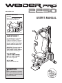
USERʼS MANUAL
M
odel No. WESY1955.1
Serial No.
Write the serial number in the
space above for reference.
Serial Number Decal (under seat)
QUESTIONS?
As a manufacturer, we are com-
mitted to providing complete
customer satisfaction. If you have
questions, or if parts are missing,
DO NOT CONTACT THE STORE;
please contact Customer Care.
IMPORTANT: You must note the
product model number and
serial number (see the drawing
above) before contacting us:
CALL TOLL-FREE:
1-877-992-5999
Mon.–Fri. 6 a.m.–6 p.m. MT
Sat. 8 a.m.–4 p.m. MT
ON THE WEB:
www.weiderservice.com
www.weider.com

2
WARNING DECAL PLACEMENT
TABLE OF CONTENTS
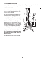
Keep hands and
fingers clear of
this area.
WARNING DECAL PLACEMENT . . . . . . . . . . . . . . . . . . . . . . . . . . . . . . . . . . . . . . . . . . . . . . . . . . . . . . . . . . . . . 2
I
MPORTANT PRECAUTIONS . . . . . . . . . . . . . . . . . . . . . . . . . . . . . . . . . . . . . . . . . . . . . . . . . . . . . . . . . . . . . . . .3
BEFORE YOU BEGIN . . . . . . . . . . . . . . . . . . . . . . . . . . . . . . . . . . . . . . . . . . . . . . . . . . . . . . . . . . . . . . . . . . . . . .4
PART IDENTIFICATION CHART . . . . . . . . . . . . . . . . . . . . . . . . . . . . . . . . . . . . . . . . . . . . . . . . . . . . . . . . . . . . . . 5
ASSEMBLY . . . . . . . . . . . . . . . . . . . . . . . . . . . . . . . . . . . . . . . . . . . . . . . . . . . . . . . . . . . . . . . . . . . . . . . . . . . . . . .7
ADJUSTMENT . . . . . . . . . . . . . . . . . . . . . . . . . . . . . . . . . . . . . . . . . . . . . . . . . . . . . . . . . . . . . . . . . . . . . . . . . . .15
WEIGHT RESISTANCE CHART . . . . . . . . . . . . . . . . . . . . . . . . . . . . . . . . . . . . . . . . . . . . . . . . . . . . . . . . . . . . . .17
TROUBLESHOOTING . . . . . . . . . . . . . . . . . . . . . . . . . . . . . . . . . . . . . . . . . . . . . . . . . . . . . . . . . . . . . . . . . . . . .18
CABLE DIAGRAMS . . . . . . . . . . . . . . . . . . . . . . . . . . . . . . . . . . . . . . . . . . . . . . . . . . . . . . . . . . . . . . . . . . . . . . .19
EXERCISE GUIDELINES . . . . . . . . . . . . . . . . . . . . . . . . . . . . . . . . . . . . . . . . . . . . . . . . . . . . . . . . . . . . . . . . . . .20
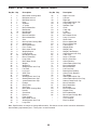
PART LIST . . . . . . . . . . . . . . . . . . . . . . . . . . . . . . . . . . . . . . . . . . . . . . . . . . . . . . . . . . . . . . . . . . . . . . . . . . . . . . 22
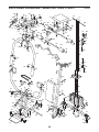
EXPLODED DRAWING . . . . . . . . . . . . . . . . . . . . . . . . . . . . . . . . . . . . . . . . . . . . . . . . . . . . . . . . . . . . . . . . . . . . 23
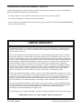
ORDERING REPLACEMENT PARTS . . . . . . . . . . . . . . . . . . . . . . . . . . . . . . . . . . . . . . . . . . . . . . . . . .Back Cover
LIMITED WARRANTY . . . . . . . . . . . . . . . . . . . . . . . . . . . . . . . . . . . . . . . . . . . . . . . . . . . . . . . . . . . . . .Back Cover
This drawing shows the location(s) of
the warning decal(s). If a decal is
missing or illegible, call the tele-
phone number on the front cover
of this manual and request a free
replacement decal. Apply the decal
in the location shown. Note: The
decal(s) may not be shown at actual
size.

3
IMPORTANT PRECAUTIONS
WARNING: To reduce the risk of serious injury, read all important precautions and
instructions in this manual and all warnings on your weight system before using your weight sys-
t
em. ICON assumes no responsibility for personal injury or property damage sustained by or
through the use of this product.
1. Before beginning any exercise program,
consult your physician. This is especially
important for persons over the age of 35 or
persons with pre-existing health problems.
2. It is the responsibility of the owner to ensure
that all users of the weight system are ade-
quately informed of all precautions.
3. Your weight system is intended for home
use only. Do not use your weight system in a
commercial, rental, or institutional setting.
4. Use your weight system only on a level sur-
face. Cover the floor beneath the weight
system to protect the floor.
5. Inspect and properly tighten all parts regu-
larly. Replace any worn parts immediately.
6. Keep children under age 12 and pets away
from your weight system at all times.
7. Your weight system should not be used by
persons weighing more than 300 lbs.
(136 kg).
8. Wear appropriate exercise clothes while
exercising; do not wear loose clothes that
could become caught on your weight sys-
tem. Always wear athletic shoes for foot
protection while exercising.
9. Keep hands and feet away from moving
parts.
10. Never release the press arm, butterfly arms,
leg lever, lat bar, or nylon strap while
weights are raised. The weights will fall with
great force.
11. Make sure that the cables remain on the pul-
leys at all times. If the cables bind while you
are exercising, stop immediately and make
sure that the cables are on the pulleys.
12. Always stand on the foot plate while per-
forming an exercise that could cause the
weight system to tip.
13. Never release the arms, leg lever, lat bar, or
handle strap while weights are raised; the
weights will fall with great force.
14. Always disconnect the lat bar from the
weight system before performing an exer-
cise that does not require the lat bar.
15. If you feel pain or dizziness while exercising,
stop immediately and begin cooling down.
16. Use your weight system only as described in
this manual.

4
BEFORE YOU BEGIN
Thank you for selecting the versatile WEIDER PRO™
2250 weight system. The weight system offers an
impressive array of weight stations designed to devel-
op every major muscle group of the body. Whether
y
our goal is to tone your body, build dramatic muscle
size and strength, or improve your cardiovascular sys-
tem, the weight system will help you to achieve the
specific results you want.
For your benefit, read this manual carefully before
you use the weight system. If you have questions
after reading this manual, please see the front cover of
this manual. To help us assist you, note the product
model number and serial number before contacting us.
The model number and the location of the serial num-
ber decal are shown on the front cover of this manual.
To avoid a registration fee for any service needed
under warranty, you must register the weight sys-
tem at www.weiderservice.com/registration.
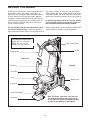
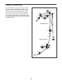
Before reading further, please familiarize yourself with
the parts that are labeled in the drawing below.
ASSEMBLED DIMENSIONS:
Height: 6 ft. 4 in. (193 cm)
Width: 3 ft. 2 in. (97 cm)
Length: 4 ft. 5 in. (135 cm)
Foot Plate
Low Pulley Station
High Pulley Station
Left Side
Right Side
Lat Bar
Leg Lever
Butterfly Arm
Press Arm
Weight Stack
Seat
Backrest
Note: The terms “right side” and “left side”
are determined relative to a person sitting
on the seat; they do not correspond to right
and left on the drawings in the manual.

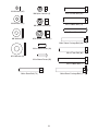
M10 x 75mm Bolt (22)
M
M10 x 67mm Bolt (11)
M10 x 80mm Bolt (16)
M10 x 90mm Bolt (85)
M
M10 x 198mm Bolt (59)
M8 x 70mm Bolt (81)
M
M8 x 117mm Bolt (68)
M
M10 x 67mm Carriage Bolt (14)
M10 x 95mm Bolt (71)
M8 x 67mm Carriage Bolt (86)
M6 x 65mm Screw (43)
5
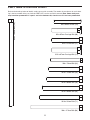
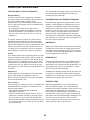
Refer to the drawings below to identify small parts used in assembly. The number in parentheses by each draw-
i
ng is the key number of the part, from the PART LIST near the end of this manual. Note: Some small parts
may have been preattached. If a part is not in the hardware kit, check to see if it has been preattached.
PART IDENTIFICATION CHART

M6 Washer (10)
M8 Washer (8)
M4 Washer (82)
M10 x 58mm Bolt (7)
M
M
10 x 45mm Bolt (83)
M10 x 48mm Bolt (12)
M
M8 x 45mm Bolt (72)
M8 x 57mm Bolt (80)
M
M6 x 50mm Carriage Bolt (38)
M6 x 50mm Screw (24)
M8 x 65mm Carriage Bolt (1)
M10 Washer (9)
M6 x 16mm Screw (18)
M4 x 20mm Screw (56)
M6 Nylon Locknut (2)
M8 Nylon Locknut (3)
M10 Nylon Locknut (21)
6

7
1
21
4
51
51
14
Small
Holes
1
5
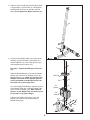
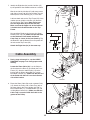
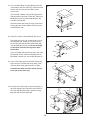
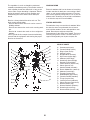
1.
Attach a Stabilizer Foot (51) to the Stabilizer (5)
with two M4 x 20mm Screws (56) and two M4
Washers (82). Attach another Stabilizer Foot in
the same way.
Insert two M10 x 67mm Carriage Bolts (14) up
through the Stabilizer (5). Insert two M8 x 65mm
Carriage Bolts (1) up through the Base (4). Note:
It may be helpful to place a piece of tape over
the bolt heads to hold the Carriage Bolts in
place.
Orient the Stabilizer (5) so that the small holes
are on the indicated side. Attach the Base (4) to
the Stabilizer with the two M10 x 67mm Carriage
Bolts (14) and two M10 Nylon Locknuts (21). Do
not tighten the Nylon Locknuts yet.
Frame Assembly
Before beginning assembly, make sure that
you have read and understand the informa-
tion in the box above.
ASSEMBLY
56
82
Before beginning assembly, carefully read the fol-
lowing information and instructions:
• Assembly requires two persons.
• Because of its size, the weight bench should be
assembled in the location where it will be used.
Make sure that there is enough clearance to walk
around the weight bench as you assemble it.
• Place all parts in a cleared area and remove the
packing materials. Do not dispose of the packing
materials until assembly is completed.
• Tighten all parts as you assemble them, unless
instructed to do otherwise.
• As you assemble the weight bench, make sure all
p
arts are oriented as shown in the drawings.
• For help identifying small parts, use the PART
IDENTIFICATION CHART on page 5.
• Assembly requires the included hex key(s)
and the following tools (not included):
two adjustable wrenches
one rubber mallet
one standard screwdriver
one Phillips screwdriver
Assembly may be more convenient if you have a
socket set, a set of open-end or closed-end
wrenches, or a set of ratchet wrenches.
M
ake Assembly Easier
Everything in this manual is designed to ensure
that the weight bench can be assembled suc-
cessfully by almost anyone. Set aside plenty of
time, so that assembly will go smoothly.

8
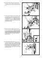
2. Slide the Front Upright (42) onto the M8 x 65mm
Carriage Bolts (1) in the Base (4). Hand tighten
two M8 Nylon Locknuts (3) onto the Carriage
B
olts. Do not tighten the Nylon Locknuts yet.
3. Attach the two Weight Guides (62) inside of the
Stabilizer (5) with two M10 x 67mm Bolts (11),
two M10 Washers (9), two 13mm Spacers (61),
and two M10 Nylon Locknuts (21).
See step 1. Tighten the M10 Nylon Locknuts
(21).
Slide two Weight Bumpers (19) onto the Weight
Guides (62). Stack the six Weights (25) on the
Weight Bumpers (19). Make sure that all of the
Weights are turned so the large pin grooves
are on the bottom of the Weights and are on
the same side of the weight stack.
Press the Weight Tube Bumper (64) into the end
of the Weight Tube (63). Insert the Weight Tube
into the stack of Weights (25). Make sure that
the pins on the Weight Tube are resting in the
pin grooves in the upper Weight.
Lubricate the insides of the holes in the Top
Weight (76). Slide the Top Weight onto the
Weight Guides (62).
2
3
42
3
1
4
62
76
21
61
9
9
11
64
63
25
Pin
Groove
19
5
Lubricate
Pin
Groove
Pin

9
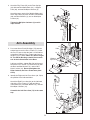
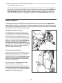
5. Press two 25mm Plastic Bushings (75) onto the
welded spacers on the Press Frame (17). Orient
the Press Frame so that the hole is in the indicat-
ed position. Slide the Press Frame into place on
the Base (4) as shown. Note: This will be a tight
fit. The Plastic Bushings should fit onto each
end of the indicated tube in the Base.
Lubricate an M10 x 198mm Bolt (59) with grease.
Attach the Press Frame (17) to the Base (4) with
the Bolt, two M10 Washers (9), and an M10
Nylon Locknut (21). Do not overtighten the
Nylon Locknut; the Press Frame must pivot
easily.
6. Identify the Right and Left Press Arms (46, 73) by
the position of the indicated holes.
Attach the Right Press Arm (46) to the indicated
side of the Press Frame (17) with two M10 x
75mm Bolts (22), four M10 Washers (9), and two
M10 Nylon Locknuts (21).
Assemble the Left Press Arm (73) in the same
way.
6
4
5
60
84
81
21
3
55
62
42
75
9
21
59
22
Holes
22
17
21
21
9
9
9
46
73
17
Tube
Lubricate
Welded
Spacers
4
Hole
9
9
9
Arm Assembly
4. Attach the Top Frame (55) to the Front Upright
(42) with two M8 x70mm Bolts (81), a Support
Plate (84), and two M8 Nylon Locknuts (3).
Attach the upper ends of the Weight Guides (62)
t
o the Top Frame (55) with an M10 x 155mm Bolt
(60), two M10 Washers (9), and an M10 Nylon
Locknut (21).
Tighten the M8 Nylon Locknuts (3) used in
steps 2 and 4.

10
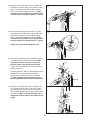
7. Identify the Right Arm (48) and the Left Arm (47)
by the position of the welded bracket on each Arm.
W
et the end of the Left Arm (47) with soapy water,
and slide a Large Pad (45) onto it. Make sure the
B
utterfly Arm Plastic Bushing (74) is in the Arm.
Lubricate both axles on the Top Frame (55). Have
another person slide the Left Arm (47) onto the
left axle on the Top Frame. Note: Do not con-
fuse the Right Arm (48) with the Left Arm.
Make sure that the upper end of the Left Arm
is behind the indicated bracket on the Top
Frame.
Set two 25mm Retainers (69) on top of a 25mm
Round Cover Cap (70). Make sure that the teeth
on the Retainers bend toward the Round
Cover Cap, as shown in the inset drawing. Tap
the Retainers and the Round Cover Cap onto the
left axle on the Top Frame (55).
Attach the Right Arm (48) in the same way.
8. During steps 8 through 19, see the CABLE
DIAGRAMS on page 19 to verify proper cable
routing.
Locate the Short Cable (58). Lay the Cable in
the bracket on the Base (4) and under the Press
Frame (17). Attach a 90mm Pulley (15) to the
bracket with an M10 x 48mm Bolt (12) and an
M10 Nylon Locknut (21). Make sure that the end
of the Cable with the ball is on the indicated
side of the bracket.
9. Route the Short Cable (58) under a 90mm Pulley
(15). Attach the Pulley and a Cable Trap (66) to
the lower hole in the Front Upright (42) with an
M10 x 95mm Bolt (71), an M10 Washer (9), and
an M10 Nylon Locknut (21). Make sure that the
Cable Trap is turned to hold the Cable in the
groove of the Pulley.
8
9
47
70
69
74
48
55
Bracket
Lubricate
Axle
15
17
21
12
4
Bracket
21
58
58
42
15
66
71
9
45
7
69
55
70
Cable Assembly

11
10. Route the Short Cable (58) around the 90mm
Pulley (15). Tighten the M10 x 80mm Bolt (16),
the M10 Washer (9), and the M10 Nylon Locknut
(
21).
11. Route the Short Cable (58) under a 90mm Pulley
(15). Attach the Pulley and a Cable Trap (66) to
the upper hole in the Front Upright (42) with an
M10 x 95mm Bolt (71), an M10 Washer (9), and
an M10 Nylon Locknut (21). Make sure that the
Cable Trap is turned to hold the Cable in the
groove of the Pulley.
12. Attach the end of the Short Cable (58) to the
Long “U”-bracket (57) with an M8 Nylon Locknut
(3) and an M8 Washer (8). See the inset draw-
ing. Do not overtighten the Nylon Locknut; it
should be threaded onto the end of the Cable
so that two threads are showing above the
Nylon Locknut.
13. Locate the Long Cable (23). Route the Long
Cable over a 90mm Pulley (15). Make sure that
the Cable is between the Pulley and the hook,
and that the end of the Cable with the ball is
on the indicated side of the hook. Attach the
Pulley with an M10 x 90mm Bolt (85) and an M10
Nylon Locknut (21).
13
10
11
12
57
23
15
Hook
Ball
85
21
58
21
15
5
8
9
16
3
8
21
58
42
15
66
71
9
58
57
3
8

12
17
14
15
16
21
50
7
6
7
48
47
47
23
50
21
6
3
23
21
12
Bracket
15
20
66
68
15
66
23
21
12
57
55
23
4
2
14. Wrap the Long Cable (23) over a “V”-pulley (6).
Attach the “V”-pulley and a Long Cable Trap (50)
to the Front Upright (42) with an M10 x 58mm
B
olt (7) and an M10 Nylon Locknut (21). Make
sure that the Long Cable Trap is positioned to
h
old the Cable in the groove of the “V”-pulley.
15. Route the Long Cable (23) around a “V”-pulley
(6). Attach the “V”-pulley and a Long Cable Trap
(50) to the Left Arm (47) with an M10 x 58mm
Bolt (7) and an M10 Nylon Locknut (21). Make
sure that the Long Cable Trap is positioned to
hold the Cable in the groove of the “V”-pulley.
Repeat this step with the Right Arm (48).
16. Route the Long Cable (23) over the 90mm Pulley
(15) attached to the Pulley Bracket (20). Make
sure that the Cable Trap (66) is oriented to
hold the Cable in the groove of the Pulley.
Tighten the M10 x 48mm Bolt (12) and the M10
Nylon Locknut (21).
Properly tighten the M8 x 117mm Bolt (68) and an
M8 Nylon Locknut (3) attaching the Pulley
Bracket (20) to the bracket on the Top Frame
(55). Do not overtighten the Nylon Locknut;
the Pulley Bracket must be able to pivot easily.
17. Wrap the Long Cable (23) under a 90mm Pulley
(15). Attach the Pulley and a Cable Trap (66) to
the indicated hole in the Long “U”-bracket (57)
with an M10 x 48mm Bolt (12) and an M10 Nylon
Locknut (21). Make sure that the Cable Trap is
oriented to hold the Cable in the groove of the
Pulley.

13
18
23
B
racket
15
83
21
20
41
10
10
43
43
23
3
72
63
8
3
67
42
19
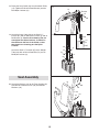
18. Route the Long Cable (23) over the 90mm Pulley
(15). Tighten the M10 x 45mm Bolt (83) and the
M10 Nylon Locknut (21).
19. Attach the Long Cable (23) to the Small “U”-
bracket (67) with an M8 Nylon Locknut (3) and an
M8 Washer (8).
See the inset drawing. Do not
overtighten the Nylon Locknut; it should be
threaded onto the end of the Cable so that
two threads are showing past the Nylon
Locknut.
Attach the Small “U”-bracket (67) to the Weight
Tube (63) with an M8 x 45mm Bolt (72) and an
M8 Nylon Locknut (3).
23
67
3
20. Attach the Backrest (41) to the Front Upright (42)
with two M6 x 65mm Screws (43) and two M6
Washers (10).
Seat Assembly
8

14
21. Insert an M6 x 50mm Carriage Bolt (38) into the
center hole in the Seat Plate (37). Attach the Seat
Plate to the Seat (13) with two M6 x 16mm
S
crews (18).
I
nsert the M6 x 50mm Carriage Bolt (38) into the
indicated hole in the Seat Frame (36). Tighten an
M6 Nylon Locknut (2) with an M6 Washer (10)
onto the Carriage Bolt.
Attach the other end of the Seat (13) to the Seat
Frame (36) with an M6 x 50mm Screw (24) and
an M6 Washer (10).
22. Lubricate an M8 x 57mm Bolt (80) with grease.
Orient the Leg Lever (29) so that the decal is on
the indicated side. Attach the Leg Lever to the
Seat Frame (36) with the M8 x 57mm Bolt (80)
and an M8 Nylon Locknut (3). Do not overtight-
en the Nylon Locknut; the Leg Lever must
pivot freely.
Insert an Eyebolt (35) into the Leg Lever (29) from
the direction shown. Attach the Eyebolt with an
M10 Nylon Locknut (21) and an M10 Washer (9).
23. Insert a Pad Tube (28) into the Seat Frame (36).
Next, wet the Pad Tube with soapy water. Then,
slide two Small Pads (30) onto the Pad Tube.
Assemble the other Pad Tube (28) to the Leg
Lever (29) in the same way.
24. Rest the Seat Frame (36) on the indicated pin in
the Front Upright (42). Attach the Seat Frame to
the Front Upright with an M8 x 67mm Carriage
Bolt (86) and the Seat Knob (40).
21
80
Lubricate
Decal
35
21
9
29
22
3
36
23
24
30
30
29
28
28
36
10
2
24
36
13
38
37
18
36
40
42
86
Pin

15
25. Make sure that all parts have been properly tightened. The use of the remaining parts will be explained
in ADJUSTMENT, beginning below.
B
efore using the weight system, pull each cable a few times to make sure that the cables move smoothly
over the pulleys. If one of the cables does not move smoothly, find and correct the problem. IMPORTANT: If
t
he cables are not properly installed, they may be damaged when heavy weight is used. See the
CABLE DIAGRAMS on page 19 of this manual for proper cable routing. If there is any slack in the
cables, you will need to remove it by tightening the cables; see TROUBLESHOOTING on page 18.
ADJUSTMENT
The instructions below describe how each part of the weight system can be adjusted. See the exercise guide
accompanying this manual to see how the weight system should be set up for each exercise. IMPORTANT:
When attaching the lat bar or handle, make sure that the attachments are in the correct starting position
for the exercise to be performed. If there is any slack in the cables or chain as an exercise is performed,
the effectiveness of the exercise will be reduced.
23
52
54
53
53
25
26
CHANGING THE WEIGHT SETTING
To change the weight setting of the weight stack,
insert the Weight Pin (26) under the desired Weight
(25). Make sure to insert the Weight Pin until the bent
end of the Weight Pin is touching the Weights, and
turn the bent end downward. The weight setting of the
weight stack can be changed from 18.5 pounds to 81
pounds, in increments of 12.5 pounds. Note: Due to
the cables and pulleys, the actual amount of
resistance at each exercise station may vary from
the weight setting. Use the WEIGHT RESISTANCE
CHART on page 17 to find the actual amount of
resistance at each weight station.
ATTACHING THE ACCESSORIES
Attach the Lat Bar (54) to the Long Cable (23) with a
Cable Clip (53). For some exercises, the Chain (52)
should be attached between the Lat Bar and the
Cable with two Cable Clips. Adjust the length of the
Chain between the Lat Bar and the Cable so the
Lat Bar is in the correct starting position for the
exercise to be performed.
The accessories can be attached to the Short
Cable (not shown) in the same way.
Note: The seat frame must be removed from the
front upright before the Short Cable (not shown)
is used with an accessory. (See ATTACHING AND
REMOVING THE SEAT on page 16.)

16
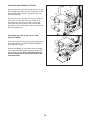
ATTACHING THE LEG LEVER TO THE LOW
PULLEY STATION
To use the Leg Lever (29), the seat must be attached
to the front upright (see ATTACHING AND REMOV-
ING THE SEAT, above).
Remove the Weight Pin (not shown) from the weight
stack. Attach the Short Cable (58) to the Eyebolt (35)
with a Cable Clip (53). Note: The Weight Pin must
also be removed when removing the Short Cable
from the Eyebolt.
53
58
29
35
ATTACHING AND REMOVING THE SEAT
Set the Seat Frame (36) onto the indicated pin on the
F
ront Upright (42). Attach the Seat Frame to the Front
Upright with an M8 x 67mm Carriage Bolt (86) and
t
he Seat Knob (40).
For some exercises, the Seat (13) must be removed.
First, make sure that the Chain (not shown) is not
attached to the Leg Lever (29). Next, remove the
Seat Knob (40) and the M8 x 67mm Carriage Bolt
(86) from the Seat Frame (36). Lift the Seat Frame off
the Front Upright (42).
40
36
42
Pin
13
29
86

17
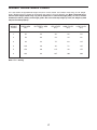
WEIGHT PRESS ARM BUTTERFLY ARM LEG LEVER HIGH PULLEY LOW PULLEY
PLATES (lbs.) (lbs.) (lbs.) (lbs.) (lbs.)
1 45 22 36 28 54
2 70 33 54 44 82
3 99 42 75 60 115
4 128 48 96 72 147
5 153 60 115 90 175
6 184 69 137 103 209
This chart shows the approximate weight resistance at each station. The numbers refer to the 12.5 lb. weight
plates. Weight resistance shown for the butterfly arm station is for each butterfly arm. Note: The actual resis-
t
ance at each weight station may vary due to differences in individual weight plates, as well as friction
between the cables, pulleys, and weight guides. Do not use the top weight by itself; the weight system
m
ay not function properly.
WEIGHT RESISTANCE CHART
Note: 1 lb. = 0.45 kg

18
TROUBLESHOOTING
I
nspect and tighten all parts each time the weight system is used. Replace any worn parts immediately. The
weight system can be cleaned with a damp cloth and mild non-abrasive detergent; do not use solvents.
TIGHTENING THE CABLES
Woven cable, the type of cable used on the weight
system, can stretch slightly when it is first used. If
there is slack in the cables before resistance is felt,
the cables should be tightened.
Slack can be removed by moving the 90mm Pulley
(15) to the lower hole in the Long “U”-bracket (57).
Remove the M10 Nylon Locknut (21) and the M10 x
48mm Bolt (12) from the Cable Trap (66), the Pulley,
and the Long “U”-bracket. Then, reattach the Pulley
and the Cable Trap. Make sure that the Cable Trap
is positioned to hold the Cable in place, and that
the Cable and the Pulley move smoothly.
Additional slack can be removed from the cables by
tightening the M8 Nylon Locknut (3) at the end of the
Long Cable (23) or at the end of the Short Cable (58).
To do this, you may need to remove the Small “U”-
bracket (67) from the Weight Tube (63) or remove the
90mm Pulley (15) from the Long “U”-bracket (57).
Make sure that the cables are not too tight, or the
Top Weight (76) will be lifted off the weight stack.
Note: If a cable tends to slip off the pulleys often,
the cable may have become twisted. Remove the
cable and re-install it.
If the cables need to be replaced, see ORDERING
REPLACEMENT PARTS on the back cover of this
manual.
57
67
63
66
15
3
3
58
23
12
21
76

CABLE DIAGRAMS
19
The cable diagrams show the proper routing of the
Long Cable (23) and the Short Cable (58). Use the
d
iagram to make sure that the two cables and the
cable traps have been assembled correctly. If the
c
ables have not been correctly routed, the weight
system will not function properly and damage may
occur. The numbers show the correct route for each
cable. Make sure that the cable traps do not touch
or bind the cables.
1
2
3
4
5
6
7
8
1
2
4
5
3
Long Cable (23)
Short Cable (58)

20
EXERCISE GUIDELINES
THE FOUR BASIC TYPES OF WORKOUTS
Muscle Building
To increase the size and strength of your muscles,
push them close to their maximum capacity. Your mus-
cles will continually adapt and grow as you
progressively increase the intensity of your exercise.
You can adjust the intensity level of an individual exer-
cise in two ways:
• by changing the amount of resistance used
• by changing the number of repetitions or sets per-
formed. (A “repetition” is one complete cycle of an
exercise, such as one sit-up. A “set” is a series of
repetitions.)
The proper amount of resistance for each exercise
depends upon the individual user. You must gauge
your limits and select the amount of resistance that is
right for you. Begin with 3 sets of 8 repetitions for each
exercise you perform. Rest for 3 minutes after each
set. When you can complete 3 sets of 12 repetitions
without difficulty, increase the amount of resistance.
Toning
You can tone your muscles by pushing them to a mod-
erate percentage of their capacity. Select a moderate
amount of resistance and increase the number of rep-
etitions in each set. Complete as many sets of 15 to
20 repetitions as possible without discomfort. Rest for
1 minute after each set. Work your muscles by com-
pleting more sets rather than by using high amounts of
resistance.
Weight Loss
To lose weight, use a low amount of resistance and
increase the number of repetitions in each set.
Exercise for 20 to 30 minutes, resting for a maximum
of 30 seconds between sets.
Cross Training
Cross training is an efficient way to get a complete and
well-balanced fitness program. An example of a bal-
anced program follows:
• Plan strength training workouts on Monday,
Wednesday, and Friday.
• Plan 20 to 30 minutes of aerobic exercise, such as
running on a treadmill or riding on an elliptical exer-
ciser or exercise cycle, on Tuesday and Thursday.
• Rest from both strength training and aerobic exercise
for at least one full day each week to give your body
time to regenerate.
The combination of strength training and aerobic exer-
c
ise will reshape and strengthen your body, plus
develop your heart and lungs.
PERSONALIZING YOUR EXERCISE PROGRAM
Determining the appropriate length of time for each
workout, and the numbers of repetitions and sets to
complete, is an individual matter. Avoid overdoing it
during the first few months of your exercise program.
Progress at your own pace and be sensitive to your
bodyʼs signals. If you experience pain or dizziness
while exercising, stop immediately and cool down.
Find out what is wrong before continuing. Remember
that adequate rest and a proper diet are important fac-
tors in any exercise program.
WARMING UP
Begin each workout with 5 to 10 minutes of stretching
and light exercise to warm up. Warming up prepares
your body for more strenuous exercise by increasing
circulation, raising your body temperature, and deliver-
ing more oxygen to your muscles.
WORKING OUT
Each workout should include 6 to 10 different exercis-
es. Select exercises for every major muscle group,
emphasizing areas that you want to develop most. To
give balance and variety to your workouts, vary the
exercises from workout to workout.
Schedule your workouts for the time of day when your
energy level is the highest. Each workout should be
followed by at least one day of rest. Once you find the
schedule that is right for you, stick with it.
EXERCISE FORM
Maintaining proper form is an essential part of an
effective exercise program. This requires moving
through the full range of motion for each exercise, and
moving only the appropriate parts of the body.
Exercising in an uncontrolled way will leave you feel-
ing exhausted. On the exercise guide accompanying
this manual you will find photographs showing the cor-
rect form for several exercises, and a list of the
muscles affected. See the muscle chart on the next
page to find the names of the muscles.
Page is loading ...
Page is loading ...
Page is loading ...
Page is loading ...
-
 1
1
-
 2
2
-
 3
3
-
 4
4
-
 5
5
-
 6
6
-
 7
7
-
 8
8
-
 9
9
-
 10
10
-
 11
11
-
 12
12
-
 13
13
-
 14
14
-
 15
15
-
 16
16
-
 17
17
-
 18
18
-
 19
19
-
 20
20
-
 21
21
-
 22
22
-
 23
23
-
 24
24


Weider 1200 User manual
- Type
- User manual
- This manual is also suitable for
Ask a question and I''ll find the answer in the document
Finding information in a document is now easier with AI
Related papers
-
Weider WESY2453 User manual
-
-
-
-
-
-
-
-
-
Other documents
-
Gold's Gym XR66 GGSY69530 User manual
-
-
Weslo Gym 1000 User manual
-
-
Sears 831.154020 User manual
-
-
Gold's Gym Platinum GGSY3058.0 User manual
-
-
-