Harbor Freight Tools Peak/11000 User manual
- Category
- Power generators
- Type
- User manual
This manual is also suitable for

ITEM 61725
Visit our website at: http://www.harborfreight.com
Email our technical support at: [email protected]
Email our engine support at: [email protected]
13,500 WATT
PORTABLE
GENERATOR
11,000 RUNNING WATTS
13,500 PEAK WATTS
Owner’s Manual & Safety Instructions
Save This Manual Keep this manual for the safety warnings and precautions, assembly,
operating, inspection, maintenance and cleaning procedures. Write the product’s serial number in the
back of the manual near the assembly diagram (or month and year of purchase if product has no number).
Keep this manual and the receipt in a safe and dry place for future reference.
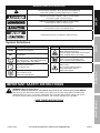
Using a generator indoors CAN
KILL YOU IN MINUTES.
Generator exhaust contains
carbon monoxide. This is a poison
you cannot see or smell.
NEVER use inside
a home or garage,
EVEN IF doors and
windows are open.
Only use OUTSIDE
and far away from
windows, doors,
and vents.
When unpacking, make sure that the product is intact
and undamaged. If any parts are missing or broken,
please call 1-888-866-5797 as soon as possible.
Copyright
©
2013 by Harbor Freight Tools
®
. All rights reserved.
No portion of this manual or any artwork contained herein may be reproduced in
any shape or form without the express written consent of Harbor Freight Tools.
Diagrams within this manual may not be drawn proportionally. Due to continuing
improvements, actual product may differ slightly from the product described herein.
Tools required for assembly and service may not be included.
Read this material before using this product.
Failure to do so can result in serious injury.
SAVE THIS MANUAL.
REV 15a

Page 2 For technical questions, please call 1-888-866-5797. ITEM 61725
Table of Contents
Specifications ............................................. 2
Safety ......................................................... 3
Setup .......................................................... 8
Operation ................................................... 16
Maintenance .............................................. 20
Troubleshooting ......................................... 24
Warranties ................................................. 26
Parts Lists and Diagrams .......................... 28
Specifications
Generator
Output
120/240VAC, 60Hz, 1 Phase
11,000W Rated
13,500W Maximum
Receptacles See Figure A: Control Panel on page 8
Displacement 670cc
Engine Type
Horizontal Dual Cylinder
4-stroke
Cooling System Forced air cooled
Fuel
Type
87+ octane stabilizer treated
unleaded gasoline
Capacity 7 Gallon
Engine Oil
Type SAE
10W-30 above 32° F
5W30 at 32° F or below
SJ class oil
Capacity 2 Quart
Run Time @ 50% Load
with full tank
7.5 hr.
Sound Level at 3 feet 78 dB
Bore x Stroke 78 mm x 70 mm
Compression Ratio 7.93:1
Rotation viewed from PTO
(power takeoff - the output shaft)
Counterclockwise
Spark Plug
Type
NGK
®
BP-6ES
NHSP
®
/ Torch
®
F6TC
Gap 0.7 - 0.8 mm
Valve Clearance
Intake 0.10 - 0.15 mm
Exhaust 0.15 - 0.20 mm
Speed Idle 1800 RPM
The emissions control system for this Engine is warranted for standards set by the
U.S. Environmental Protection Agency. For warranty information, refer to the last pages of this manual.

Page 3For technical questions, please call 1-888-866-5797.ITEM 61725
SAFETYOPERATIONMAINTENANCE SETUP
WARNING SYMBOLS AND DEFINITIONS
This is the safety alert symbol. It is used to alert you to potential
personal injury hazards. Obey all safety messages that
follow this symbol to avoid possible injury or death.
Indicates a hazardous situation which, if not avoided,
will result in death or serious injury.
Indicates a hazardous situation which, if not avoided,
could result in death or serious injury.
Indicates a hazardous situation which, if not avoided,
could result in minor or moderate injury.
Addresses practices not related to personal injury.
Symbol Definitions
Symbol Property or Statement
RPM
Revolutions Per Minute
HP
Horsepower
WARNING marking concerning
Risk of Eye Injury. Wear ANSI-approved
safety goggles with side shields.
Read the manual before
set-up and/or use.
WARNING marking concerning
Risk of Hearing Loss.
Wear hearing protection.
Symbol Property or Statement
WARNING marking concerning
Risk of Respiratory Injury.
Operate engine OUTSIDE and far away
from windows, doors, and vents.
WARNING marking concerning
Risk of Fire while handling fuel.
Do not smoke while handling fuel.
WARNING marking concerning
Risk of Fire.
Do not refuel while operating.
Keep flammable objects
away from engine.
IMPORTANT SAFETY INSTRUCTIONS
WARNING! Read all instructions.
Failure to follow all instructions listed below may result in fire, serious injury and/or DEATH.
The warnings and precautions discussed in this manual cannot cover all possible conditions and
situations that may occur. It must be understood by the operator that common sense and caution
are factors which cannot be built into this product, but must be supplied by the operator.
SAVE THESE INSTRUCTIONS

Page 4 For technical questions, please call 1-888-866-5797. ITEM 61725
SAFETY OPERATION MAINTENANCESETUP
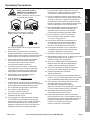
Set up Precautions
1. Gasoline fuel and fumes are flammable, and
potentially explosive. Use proper fuel storage
and handling procedures. Do not store fuel
or other flammable materials nearby.
2. Have multiple ABC class fire extinguishers nearby.
3. Operation of this equipment may create sparks that
can start fires around dry vegetation.
A spark arrestor may be required. The operator
should contact local fire agencies for laws or
regulations relating to fire prevention requirements.
4. Set up and use only on a flat, level,
well-ventilated surface.
5. All connections and conduits from the Generator
to the load must only be installed by trained and
licensed electricians, and in compliance with all
relevant local, state, and federal electrical codes and
standards, and other regulations where applicable.
6. Connections for standby power to a building
electrical system must be made by a qualified
electrician. The connection must isolate the
generator power from utility power, and must comply
with all applicable laws and electrical codes.
7. Wear ANSI-approved safety goggles, heavy-duty
work gloves, and dust mask/respirator during set up.
8. Use only lubricants and fuel recommended
in the Specifications chart of this manual.
9. Improper connections to a building electrical system
can allow electrical current from the generator
to backfeed into the utility lines. Such backfeed
may electrocute utility company workers or others
who contact the lines during a power outage,
and the generator may explode, burn, or cause
fires when utility power is restored. Consult
the utility company and a qualified electrician if
intending to use the generator for back up power.
10. Do not operate the Generator before grounding.
The Generator must be earth-grounded
in accordance with all relevant electrical
codes and standards before operation.

Page 5For technical questions, please call 1-888-866-5797.ITEM 61725
SAFETYOPERATIONMAINTENANCE SETUP
Operating Precautions
1. CARBON MONOXIDE HAZARD
Using a generator indoors
CAN KILL YOU IN MINUTES.
Generator exhaust contains
carbon monoxide. This is a poison
you cannot see or smell.
NEVER use inside a home or garage,
EVEN IF doors and windows are open.
Only use OUTSIDE and far away from windows,
doors, and vents.
2. Never use a generator indoors, including in
garages, basements, crawl spaces and sheds.
Opening doors and windows or using fans will NOT
prevent carbon monoxide build up in the home.
3. When using generators, keep them outdoors
and far away from open doors, windows,
and vents to avoid toxic levels of carbon
monoxide from building up indoors.
4. If you start to feel sick, dizzy, or weak while
using a generator, get to fresh air right away.
The carbon monoxide from generators can
quickly lead to full incapacitation and death.
5. Keep children away from the equipment,
especially while it is operating.
6. Keep all spectators at least six feet
from the Engine during operation.
7. Fire Hazard! Do not fill fuel tank while engine is
running. Do not operate if gasoline has been spilled.
Clean spilled gasoline before starting engine.
Do not operate near pilot light or open flame.
8. Do not touch engine during use.
Let engine cool down after use.
9. Never store fuel or other flammable
materials near the engine.
10. If the plugged in product operates abnormally
or unusually slow, immediately stop using the
generator as a power source. Read and adhere
to the instruction manual of the product to be
powered to make sure that it can be safely and
efficiently powered by a portable generator.
11. Before connecting an appliance or power cord
to the generator: Make sure that it is in good
working order. Faulty appliances or power cords
can create a potential for electrical shock.
12. Do not exceed the maximum power rating of the
generator. Make sure that the total electrical rating
of the all of the tools or appliances plugged into
the generator at the same time does not exceed
that of the generator. Check that the startup surge
will not be beyond the limit of the Generator.
13. Avoid substantially overloading which will trip
the circuit breaker. Slightly overloading the
generator may not trip the circuit breaker,
but will lead to premature generator failure.
14. Do not attempt to connect or disconnect
load connections while standing in water,
or on wet or soggy ground.
15. Do not touch electrically energized parts of
the Generator and interconnecting cables
or conductors with any part of the body, or
with any non-insulated conductive object.
16. Connect the Generator only to a load that is
compatible with the electrical characteristics
and rated capacities of the Generator.
17. Insulate all connections and disconnected wires.
18. Guard against electric shock. Prevent body contact
with grounded surfaces such as pipes,
radiators, ranges, and refrigerators.
19. Only use a suitable means of transport and
lifting devices with sufficient weight bearing
capacity when transporting the generator.
20. Secure the generator on transport vehicles to
prevent it from rolling, slipping, and tilting.
21. Industrial applications must follow
OSHA requirements.
22. Do not leave the generator unattended when it is
running. Turn off the generator (and remove safety
keys, if available) before leaving the work area.
23. The generator can produce high noise levels.
Prolonged exposure to noise levels
above 85 dBA is hazardous to hearing.
Wear ear protection when operating the generator
or when working nearby while it is operating.
24. Wear ANSI-approved safety glasses
and hearing protection during use.
25. People with pacemakers should consult their
physician(s) before use. Electromagnetic fields in
close proximity to a heart pacemaker could cause
pacemaker interference or pacemaker failure.
Caution is necessary when near the
engine’s magneto or recoil starter.

Page 6 For technical questions, please call 1-888-866-5797. ITEM 61725
SAFETY OPERATION MAINTENANCESETUP
26. Use only accessories that are recommended
by Harbor Freight Tools for your model.
Accessories that may be suitable for one
piece of equipment may become hazardous
when used on another piece of equipment.
27. Do not operate in explosive atmospheres,
such as in the presence of flammable
liquids, gases, or dust. Gasoline-powered
engines may ignite the dust or fumes.
28. Stay alert, watch what you are doing and
use common sense when operating this
generator. Do not use while tired or under the
influence of drugs, alcohol or medication.
29. Dress properly. Do not wear loose clothing or
jewelry. Keep hair, clothing and gloves away
from moving parts. Loose clothes, jewelry or
long hair can be caught in moving parts.
30. Parts, especially exhaust system components,
get very hot during use. Stay clear of hot parts.
31. Do not cover the generator during operation.
32. Keep the generator and surrounding
area clean at all times.
33. Use the equipment, accessories, etc., in
accordance with these instructions and in the
manner intended for the particular type of
equipment, taking into account the working
conditions and the work to be performed.
Use of the equipment for operations different from
those intended could result in a hazardous situation.
34. Do not operate the equipment with known
leaks in the engine’s fuel system.
35. WARNING: This product contains or, when
used, produces a chemical known to the State
of California to cause cancer and birth defects
or other reproductive harm. (California Health
& Safety Code § 25249.5, et seq.)
36. When spills of fuel or oil occur, they must be
cleaned up immediately. Dispose of fluids and
cleaning materials as per any local, state, or
federal codes and regulations. Store oil rags in
a bottom-ventilated, covered, metal container.
37. Keep hands and feet away from moving parts.
Do not reach over or across
equipment while operating.
38. Before use, check for misalignment or binding of
moving parts, breakage of parts, and any other
condition that may affect the equipment’s operation.
If damaged, have the equipment serviced
before using. Many accidents are caused
by poorly maintained equipment.
39. Use the correct equipment for the application.
Do not modify the equipment and do not use the
equipment for a purpose for which it is not intended.
Operating Precautions (cont.)

Page 7For technical questions, please call 1-888-866-5797.ITEM 61725
SAFETYOPERATIONMAINTENANCE SETUP
Service Precautions
1. Before service, maintenance, or cleaning:
a. Unplug all devices from the generator.
b. Turn the engine switch to its “OFF” position.
c. Allow the engine to completely cool.
d. Then, remove the spark plug cap
from the spark plug.
2. Keep all safety guards in place and in
proper working order. Safety guards include
muffler, air cleaner, mechanical guards,
and heat shields, among other guards.
3. Keep all electrical equipment clean and dry.
Replace any wiring where the insulation is
cracked, cut, abraded, or otherwise degraded.
Replace terminals that are worn, discolored, or
corroded. Keep terminals clean and tight.
4. Do not alter or adjust any part of the
equipment or its engine that is sealed by the
manufacturer or distributor. Only a qualified
service technician may adjust parts that may
increase or decrease governed engine speed.
5. Wear ANSI-approved safety goggles,
heavy-duty work gloves, and
dust mask/respirator during service.
6. Maintain labels and nameplates on the equipment.
These carry important information.
If unreadable or missing, contact
Harbor Freight Tools for a replacement.
7. Have the equipment serviced by a qualified repair
person using only identical replacement parts.
This will ensure that the safety of the equipment
is maintained. Do not attempt any service or
maintenance procedures not explained in this
manual or any procedures that you are uncertain
about your ability to perform safely or correctly.
8. Store equipment out of the reach of children.
9. Follow scheduled engine and
equipment maintenance.
Refueling:
1. Do not smoke, or allow sparks, flames,
or other sources of ignition around the
equipment, especially when refuelling.
2. Do not refill the fuel tank while the
engine is running or hot.
3. Do not fill fuel tank to the top.
Leave a little room for the fuel to expand as needed.
4. Refuel in a well-ventilated area only.
5. Wipe up any spilled fuel and allow excess
to evaporate before starting engine.
To prevent FIRE, do not start the engine
while the smell of fuel hangs in the air.
SAVE THESE INSTRUCTIONS.

Page 8 For technical questions, please call 1-888-866-5797. ITEM 61725
SAFETY OPERATION MAINTENANCESETUP
Set Up
Read the ENTIRE IMPORTANT SAFETY INFORMATION section at the beginning of this manual
including all text under subheadings therein before set up or use of this product.
TO PREVENT SERIOUS INJURY:
Operate only with proper spark arrestor installed.
Operation of this equipment may create sparks that can start fires around dry vegetation.
A spark arrestor may be required.
The operator should contact local fire agencies for laws or regulations
relating to fire prevention requirements.
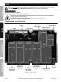
Components and Controls
Display
Switch
Choke Knob
120/240VAC
46A Breakers
Low Oil Indicator
120/240VAC 46A
Receptacle
120/240VAC
30A Receptacle
and Breakers
120VAC 30A
Receptacle
and Breaker
120VAC 20A
Receptacles
and Breaker
120VAC 20A
Receptacles
and Breaker
Ground
Terminal
12VDC Receptacle
and Breaker
Figure A: Control Panel

Page 9For technical questions, please call 1-888-866-5797.ITEM 61725
SAFETYOPERATIONMAINTENANCE SETUP
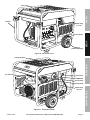
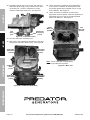
Control Panel
Battery
(sold separately)
Handle
Spark Plug
(1 of 2)
Fuel Cap
Figure B: Generator Front
Lifting Bracket
Fuel Valve
Muffler
Oil Fill Plug
Dipstick
Spark Plug
(2 of 2)
Air Cleaner
Figure C: Generator Back

Page 10 For technical questions, please call 1-888-866-5797. ITEM 61725
SAFETY OPERATION MAINTENANCESETUP
High Altitude Operation Above 3000 feet
WARNING! TO PREVENT SERIOUS INJURY FROM FIRE:
Follow instructions in a well-ventilated area away from ignition sources.
If the engine is hot from use, shut the engine off and wait for it to cool before proceeding. Do not smoke.
NOTICE: Warranty void if necessary adjustments are not made for high altitude use.
At high altitudes, the engine’s carburetor, governor, and any other parts that control the fuel-air ratio will need
to be adjusted by a qualified mechanic to allow efficient high-altitude use and to prevent damage to the engine
and any other devices used with this product. The fuel system on this engine may be influenced by operation
at higher altitudes. Proper operation can be ensured by installing an altitude kit at altitudes higher than 3000 ft.
above sea level. At elevations above 8000 ft, the engine may experience decreased performance, even with
the proper main jet. Operating this engine without the proper altitude kit installed may increase the engine’s
emissions and decrease fuel economy and performance. The kit should be installed by a qualified mechanic.
High Altitude Kit Parts List - A
Part Description Qty
A1 Left Main Jet 3000-6000 ft. 1
A2 Right Main Jet 3000-6000 ft. 1
A3 Left Main Jet 6000-8000 ft. 1
Part Description Qty
A4 Right Main Jet 6000-8000 ft. 1
137d Outer Bowl O-ring (replacement) 1
137e Inner Bowl O-ring (replacement) 1
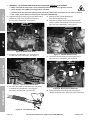
Disassembly
1. Turn off the engine.
2. Close the fuel valve.
3. Remove the Air Cleaner Top Knob (142a) and the
two Air Cleaner Front Knobs (102). See Figure D.
Air Cleaner
Top Knob (142a)
Air Cleaner
Front Knob
(102)
Figure D: Remove Knobs
4. Remove the Air Cleaner Front Cover (101),
pulling it up then out. See Figure E.
Air Cleaner
Front Cover (101)
Figure E: Remove Front Cover

Page 11For technical questions, please call 1-888-866-5797.ITEM 61725
SAFETYOPERATIONMAINTENANCE SETUP
5. Remove the Air Cleaner Top Cover (142b) and
internal Air Cleaner components
(Spacer, Foam and Paper Filters (142c-142e)).
See Figure F.
Air Cleaner
Top Cover
(142b)
Air Cleaner
Spacer (142c)
Foam Air
Filter (142d)
Paper Air
Filter (142e)
Figure F: Remove Air Cleaner
Top Cover and components
6. Remove the two Intake Cover Bolts (143) and the
two Air Cleaner Base Bolts (146). See Figure G.
7. Detach the top of the Fuel Filter Clip (147)
from the Air Cleaner Base (142g).
Intake Cover
Bolts (143)
Air Cleaner
Base Bolts
(146)
Fuel Filter
Clip (147)
Air Cleaner
Base (142g)
Figure G: Remove Bolts and Clip
from Air Cleaner Base
8. Remove the Air Cleaner Base.
9. Remove the four Shroud Nuts (99) and the two
Flange Shoulder Bolts (112) from the Shroud (100).
The Flange Shoulder Bolt on the right holds the
Lifting Bracket (111) in place. See Figure H.
Shroud
Nuts (99)
Flange
Shoulder
Bolt (112)
Flange Shoulder
Bolt (112)
behind Lifting Bracket
Shroud (100)
Note: Air Cleaner Front Cover is still shown,
although it should have been removed in step 4.
Figure H: Remove Shroud
10. Remove the Shroud.

Page 12 For technical questions, please call 1-888-866-5797. ITEM 61725
SAFETY OPERATION MAINTENANCESETUP
11. WARNING! TO PREVENT SERIOUS INJURY FROM FIRE, BEFORE CONTINUING:
a. Make sure that the work area is well-ventilated and that there are no ignition sources.
b. Have multiple class ABC fire extinguishers available.
c. Double-check that fuel hose leading from fuel tank to Fuel Filter is clamped or fuel valve is closed.
d. Use a safe, proper means to clean up all fuel spills immediately.
12. Squeeze the Spring Clamp (140) and slide it back.
Detach the Fuel Hose (141) from the port at
the top of the Carburetor. See Figure I.
Spring
Clamp (140)
fuel
port
Fuel
Hose (141)
Figure I: Detach Fuel Hose
13. Locate the Throttle Rod (174) connection on
the left side of the carburetor. See Figure J.
Throttle
Rod (174)
Throttle Rod
Spring (175)
Throttle Rod
Clip (139)
Figure J: Disconnect Throttle Rod
14. A: Swing the black Throttle Rod Clip (139) down
to release the Throttle Rod. See Figure K.
B: Pull the Throttle Rod out of the Clip.
A
B
Figure K: Throttle Rod Clip
15. Disconnect the Throttle Rod Spring
from the Throttle Rod Clip.
16. Squeeze the Spring Wire Clamp (32) and slide
it back. Detach the Breather Hose (33) from the
right side of the Carburetor. See Figure L.
Spring Wire
Clamp (32)
Breather
Hose (33)
Figure L: Detach Breather Hose
17. Locate the Choke Rod (177) connection on the
right side of the carburetor. See Figure M.
Choke
Rod (177)
Choke Rod
Clip (176)
Figure M: Disconnect Choke Rod
18. Swing the black Choke Rod Clip (176) aside to
release the Choke Rod. Disconnect the Choke Rod.

Page 13For technical questions, please call 1-888-866-5797.ITEM 61725
SAFETYOPERATIONMAINTENANCE SETUP
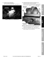
19. At the front of the Carburetor,
remove the Bolt (38) holding the
Fuel Pump Bracket (40) in place. See Figure N.
Fuel Pump
Bracket (40)
Bolt (38)
Figure N: Remove Fuel Pump Bracket
20. Underneath where the Fuel Pump Bracket was,
the Solenoid Valve (138) is connected.
Note the location of the green wire and green dot on
the connector. Unplug the connector. See Figure O.
Solenoid wire
connector
Note location
of dots here.
Bolt (133)
Carburetor
Intake Elbow
(131)
Bolt
(132)
Bolt
(132)
Figure O: Disconnect Solenoid Valve wire connector
21. Remove Bolt (133) and two Bolts (132) from the
Carburetor Intake Elbow (131). See Figure O.
22. Remove the Carburetor assembly from the engine.
Keep it upright, it may contain fuel.

Page 14 For technical questions, please call 1-888-866-5797. ITEM 61725
SAFETY OPERATION MAINTENANCESETUP
23. Hold the fuel drain port over a bowl, and open the
Carburetor Drain Plug (137a) to allow fuel to drain
out of that port. Once the carburetor is empty,
close the Carburetor Drain Plug. See Figure P.
Carburetor
Drain Plug
(137a)
fuel
drain
port
Figure P: Carburetor Drain
24. Turn the Carburetor assembly over.
25. Remove the four Carburetor Bowl Bolts (137b) and
remove the Carburetor Bowl (137c). See Figure Q.
Carburetor
Bowl Bolt
(137b)
Carburetor
Bowl Bolt
(137b)
Carburetor
Bowl
(137c)
Carburetor
Bowl Bolt
(137b)
Carburetor
Bowl Bolt
(137b)
Figure Q: Carburetor Bowl Bolts
26. Use a carburetor screwdriver (sold separately)
to remove the Left Main Jet and replace it with
the proper replacement Left Main Jet (A1 or A3)
for the altitude. See Figure R.
27. Use a carburetor screwdriver to remove the
Right Main Jet and replace it with the replacement
Right Main Jet (A2 or A4) for the same altitude
as the Left Main Jet. See Figure R.
Right
Main Jet
(A2/A4)
Left
Main Jet
(A1/A3)
Note: Since carburetor is upside-down,
left and right sides are reversed.
Figure R: Main Jets

Page 15For technical questions, please call 1-888-866-5797.ITEM 61725
SAFETYOPERATIONMAINTENANCE SETUP
Reassembly
Note: Reassembly step references shown in brackets.
1. Replace the Outer and Inner Bowl O-rings
(137d, 137e) with the replacements
from the altitude kit. Do not reuse existing O-rings.
Carburetor
Bowl
Outer Bowl
O-ring
Inner Bowl
O-ring
Figure S: Replace Bowl O-rings
2. Assemble the Carburetor Bowl using four
Carburetor Bowl Bolts. [#25] Assemble Carburetor
Intake Elbow to Intake using Bolts. [#21]
3. Attach Solenoid Valve connector, line up green
wire with the green dot on the connector. [#20]
4. Attach Fuel Pump Bracket to front of intake
using Bolt. Gently lift the Bracket after
assembly to ensure proper alignment. [#19]
5. Attach the Choke Rod on the right side of the
Carburetor, and secure it with its Clip. [#17,18]
6. Attach the Breather Hose to the Carburetor,
and secure it with its Clamp. [#16]
7. Attach the Throttle Rod Spring to the Throttle Rod
Clip on the left side of the Carburetor. [#15]
8. Insert the Throttle Rod on the left side of the
Carburetor, and secure it with its Clip. [#14]
9. Attach the Fuel Hose to the port at the top of the
Carburetor and attach it using its Clamp. [#12]
10. Install Shroud using four Shroud Bolts and two
Flange Shoulder Bolts. [#9,10] Include the Lifting
Bracket in place on the right Flange Shoulder Bolt.
11. Install Air Cleaner Base using two Air Cleaner Base
Bolts. Connect Fuel Filter Clip under left side of
Air Cleaner Base. Install the Intake Cover and
Intake Screen using the Intake Cover Bolts. [#6-8]
12. Place the Paper Air Filter, Foam Air Filter,
Air Cleaner Spacer, and Air Cleaner Top Cover
into place on the Air Cleaner Base. [#5]
13. Replace the Air Cleaner Front Cover. [#4]
14. Use the Air Cleaner Top Knob and Air Cleaner
Front Knobs to secure the Covers in place. [#3]
15. Once all connections are secure, open fuel valve.
16. Wipe up any spilled fuel and allow excess
to evaporate before starting engine.
To prevent FIRE, do not start the engine
while the smell of fuel hangs in the air.
Battery Setup Instructions
1. Place a fully charged, lead-acid 12 volt,
36 Ah battery (not included) in a stable,
flat location near the engine.
2. Use provided battery cables only.
3. Attach the positive cable securely to
the positive battery terminal to prevent
disconnection and short circuits.
4. Attach the negative cable securely to
the negative battery terminal to prevent
disconnection and short circuits.
5. Coat the terminals and cable ends with
a corrosion-preventive coating.
Grounding
1. The Generator must be properly grounded
in accordance with all relevant electrical
codes and standards before operation.
Have the unit grounded by a qualified electrician
if you are not qualified to do so.
2. To ground the Generator, connect a #XX AWG
grounding wire (not included) from the
Grounding Terminal on the Control Panel
to a grounding rod (not included).
The grounding rod must be an earth-driven
copper or brass rod (electrode) which can
adequately ground the Generator.
3. Refer to local regulations for
ground source information.

Page 16 For technical questions, please call 1-888-866-5797. ITEM 61725
SAFETY OPERATION MAINTENANCESETUP
Operation
Read the ENTIRE IMPORTANT SAFETY INFORMATION section at the beginning of this manual
including all text under subheadings therein before set up or use of this product.
Pre-Start Checks
Inspect engine and equipment looking for damaged, loose, and missing parts before set up and starting.
If any problems are found, do not use equipment until fixed properly.
Checking and Filling Engine Oil
NOTICE: Your Warranty is VOID if the engine’s
crankcase is not properly filled with oil before
each use. Before each use, check the oil level.
Do not run the engine with low or no engine oil.
Running the engine with no or low engine oil
WILL permanently damage the engine.
1. Make sure the engine is stopped and is level.
2. Close the Fuel Valve.
3. On the back of the Generator, pull the Dipstick out,
and wipe its end off with a clean, lint free rag.
4. Reinsert the Dipstick fully and remove it to
check the oil level. The oil level should be
up to the full level as shown in Figure U.
5. If the oil level is at or below the low mark:
a. Clean the top of the yellow Oil Fill Cap
and the area around it.
b. Remove the Oil Fill Cap by turning
it counterclockwise.
c. Add the appropriate type of oil until the oil level
is at the proper level. SAE 10W-30 oil is
recommended for general use.
(Table A: SAE Viscosity Grades on page 21 in
the Maintenance section shows other viscosities
to use in different average temperatures.)
6. Thread the Oil Fill Cap back in
and reinsert the Dipstick.
NOTICE: Do not run the engine with too little oil.
The engine will be permanently damaged.
Oil Fill Cap
(yellow)
Dipstick
Figure T: Oil Fill Cap and Dipstick
(on back of Generator)
Full Level
Dipstick
Engine
Crankcase
Figure U: Oil Fill Level

Page 17For technical questions, please call 1-888-866-5797.ITEM 61725
SAFETYOPERATIONMAINTENANCE SETUP
Checking and Filling Fuel
WARNING! TO PREVENT SERIOUS
INJURY FROM FIRE:
Fill the fuel tank in a well-ventilated area
away from ignition sources. If the engine is
hot from use, shut the engine off and wait
for it to cool before adding fuel.
Do not smoke.
1. Clean the Fuel Cap and the area around it.
2. Unscrew and remove the Fuel Cap.
3. If needed, fill the Fuel Tank to about 1 inch under
the fill neck of the Fuel Tank with 87 octane or
higher unleaded gasoline that has been treated
with a fuel stabilizer additive. Follow fuel stabilizer
manufacturer’s recommendations for use.
Note: Do not use gasoline containing more than
10% ethanol (E10). Do not use E85 ethanol.
Note: Do not use gasoline that has been stored in a
metal fuel container or a dirty fuel container. It can
cause particles to enter the carburetor, effecting
engine performance and/or causing damage.
4. Then replace the Fuel Cap.
5. Wipe up any spilled fuel and allow excess
to evaporate before starting engine.
To prevent FIRE, do not start the engine
while the smell of fuel hangs in the air.

Page 18 For technical questions, please call 1-888-866-5797. ITEM 61725
SAFETY OPERATION MAINTENANCESETUP
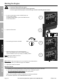
Starting the Engine
Before starting the engine:
a. Inspect the generator and engine.
b. Disconnect all electrical loads from the generator.
c. Fill the engine with the proper amount and type of both unleaded gasoline and oil.
1. To start a cold engine, pull the START Knob out
to the START position.
To restart a warm engine, push the START Knob in
to the RUN position.
2. Open the Fuel Valve.
3. Turn the Engine Switch to START.
4. Allow the Engine to run for several seconds.
Then, if the START lever is in the START position,
move the START Lever very slowly to its RUN position.
Note: Moving the START Lever too
fast could stall the engine.
IMPORTANT: Allow the engine to run at no load for five minutes with no
load after each start-up so that the engine can stabilize.
5. Adjust the Throttle as needed.
Break-in Period:
a. Breaking-in the engine will help to ensure proper equipment and engine operation.
b. The break-in period will last about 25 hours of use. DO NOT exceed
75% of the Generator’s rated capacity during this period.
• Change the engine oil after this period.
Under normal operating conditions subsequent maintenance follows
the schedule explained in the MAINTENANCE section.
1
2
3
ON
OFF START
4
OFF
ON

Page 19For technical questions, please call 1-888-866-5797.ITEM 61725
SAFETYOPERATIONMAINTENANCE SETUP
Connecting Loads to the Generator
Load and Circuit Breaker:
1. The total combined load through the outlet
on the Generator must not exceed the
rated maximum power of the unit.
2. Reduce the load if the AC Circuit Breaker turns off.
Once the load is reduced, press the Circuit Breaker
Button to reset the Generator and continue operation.
Calculate Power Draw:
Power draw can be calculated by multiplying volts
and amps. The resulting number is wattage.
• Never exceed the rated maximum wattage for
the Generator or any outlet amperage rating.
• Refer to appliance/tool owner’s manuals to
determine the wattage of electrical load devices.
• Long power cords and extension cords draw
additional power. Keep cord length at a minimum.
Wattage Estimates
Wattages listed below are estimates for that
type of equipment only. Check nameplate wattages
on all loads before connecting to Generator.
This Unit Can Power Any
One of the Following Items:
Running
Watts
Start-up
Watts
1/4 HP Air Compressor 600 900
1/6 HP Motor 500 800
3/8" Drill 400 600
Mini Refrigerator 400 700
Table/Box Fan 200
15 Amp Battery Charger 380
String Trimmer 350
Hedge Trimmer 500
Radio 50
Ten 75 Watt Light Bulbs 750
3. Allow the Engine to run at no load for five minutes
after each start-up to allow the Engine to stabilize.
Figure V: Plug Load In
4. Plug the power cord of the 120 volt appliance/
tool into the 120 volt AC Outlet on the Generator.
Note: Do not allow the generator to completely run out of fuel with devices attached.
A generator’s output may sharply spike as it runs out of fuel, causing damage to attached devices.
Stopping the Engine
1. To stop the engine in an emergency,
turn the Engine Switch off.
2. Under normal conditions, use the following procedure:
a. Remove all electrical load devices
from the Generator.
b. Turn the Engine Switch off.
c. Close the Fuel Valve.
NOTICE
See Long-Term Storage on page 23
for complete storage instructions.

Page 20 For technical questions, please call 1-888-866-5797. ITEM 61725
SAFETY OPERATION MAINTENANCESETUP
Maintenance
WARNING
TO PREVENT SERIOUS INJURY FROM ACCIDENTAL STARTING:
Turn the Power Switch of the equipment to its “OFF” position, wait for the engine to cool, and disconnect
the spark plug cap before performing any inspection, maintenance, or cleaning procedures.
TO PREVENT SERIOUS INJURY FROM EQUIPMENT FAILURE:
Do not use damaged equipment. If abnormal noise, vibration, or excess
smoking occurs, have the problem corrected before further use.
Follow all service instructions in this manual. The engine may fail critically if not serviced properly.
Many maintenance procedures, including any not detailed in this manual, will need to be performed
by a qualified technician for safety. If you have any doubts about your ability to safely service the
equipment or engine, have a qualified technician service the equipment instead.
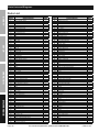
Cleaning, Maintenance, and Lubrication Schedule
Note: This maintenance schedule is intended solely as a general guide. If performance decreases or if
equipment operates unusually, check systems immediately. The maintenance needs of each piece of equipment
will differ depending on factors such as duty cycle, temperature, air quality, fuel quality, and other factors.
Note: The following procedures are in addition to the regular checks and maintenance
explained as part of the regular operation of the engine and equipment.
Procedure
Before
Each Use
Monthly or
every 20
hr. of use
Every 3 mo. or
50 hr. of use
Every 6 mo. or
100 hr. of use
Yearly or
every 300
hr. of use
Every
2 Years
Brush off outside of engine
Check engine oil level
Check air cleaner
Check sediment cup
Change engine oil
Clean air filter
*
Check and clean spark plug
1. Check/adjust idle speed
2. Check/adjust valve clearance
3. Clean fuel tank, strainer
and carburetor
4. Clean carbon build-up from
combustion chamber
** **
Replace fuel line if necessary
**
*Service more frequently when used in dusty areas.
**These items should be serviced by a qualified technician.
Page is loading ...
Page is loading ...
Page is loading ...
Page is loading ...
Page is loading ...
Page is loading ...
Page is loading ...
Page is loading ...
Page is loading ...
Page is loading ...
Page is loading ...
Page is loading ...
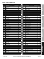
-
 1
1
-
 2
2
-
 3
3
-
 4
4
-
 5
5
-
 6
6
-
 7
7
-
 8
8
-
 9
9
-
 10
10
-
 11
11
-
 12
12
-
 13
13
-
 14
14
-
 15
15
-
 16
16
-
 17
17
-
 18
18
-
 19
19
-
 20
20
-
 21
21
-
 22
22
-
 23
23
-
 24
24
-
 25
25
-
 26
26
-
 27
27
-
 28
28
-
 29
29
-
 30
30
-
 31
31
-
 32
32


Harbor Freight Tools Peak/11000 User manual
- Category
- Power generators
- Type
- User manual
- This manual is also suitable for
Ask a question and I''ll find the answer in the document
Finding information in a document is now easier with AI
Related papers
-
Pittsburgh Automotive 1000 lb. Capacity Engine Support Bar Owner's manual
-
Harbor Freight Tools Peak/2200 User manual
-
-
-
-
-
-
-
-
Other documents
-
 DEEGO CAT6-01Black User manual
-
Predator Item 64931 Owner's manual
-
Smith Blair Inc 24500066306000 Installation guide
-
Bauer 56202 Owner's manual
-
 NIK EP2800i User manual
-
Predator Item 57080-UPC 792363570800 Owner's manual
-
-
Central Machinery Item 97869-UPC 193175328304 Owner's manual
-
-
Predator 63086 Owner's manual

