Harman Kardon AVR 230 Owner's manual
- Category
- AV receivers
- Type
- Owner's manual

DIGITAL LOGIC 7
VID 1
DVD
CD
FMAM
TAPE
6 8 CH
VID 2
VID 3
VID 4
PRO LOGIC
3 STEREO DSP
5 CH. STEREO
SURR. OFF
AVR 230
AUDIO/VIDEO RECEIVER
OWNER’S MANUAL
Power for the Digital Revolution.
®
®

AVR 230 AUDIO/VIDEO RECEIVER
3 Introduction
4 Important Safety Information
4 Unpacking
5 Front-Panel Controls
7 Rear-Panel Connections
10 Main Remote Control Functions
13 Installation and Connections
15 System Configuration
15 Speaker Placement
15 System Setup
17 Input Setup
17 Surround Setup
18 Speaker Setup
20 Delay Settings
21 Output Level Adjustment
21 Using EzSet
22 Manual Output Level Adjustment
24 Operation
24 Basic Operation
24 Source Selection
24 6-Channel/8-Channel Direct Input
24 Volume Control
24 Surround Mode Selection
25 Digital Audio Playback
26 Surround Mode Chart
28 Tuner Operation
29 Tape Recording
29 Output Level Trim Adjustment
30 Advanced Features
30 Display Brightness
30 Turn-On Volume Level
30 Semi-OSD Settings
31 Full-OSD Time-Out Adjustment
32 Programming the Remote
32 Programming the Remote
32 Direct Code Entry
32 Auto Search Method
32 Code Readout
32 Macro Programming
33 Programmed Device Functions
34 Volume Punch-Through
34 Channel Control Punch-Through
34 Transport Control Punch-Through
34 Reassigning Device Control
Selectors
35 Resetting the Remote Memory
36 Function List
38 Setup Code Tables
48 Troubleshooting Guide
48 Processor Reset
49 Technical Specifications
49 Trademark Acknowledgements
2 TABLE OF CONTENTS
Typographical Conventions
In order to help you use this manual with the remote control, front-panel controls and rear-panel connections,
certain conventions have been used.
EXAMPLE – (bold type) indicates a specific remote control or front-panel button, or rear-panel
connection jack
EXAMPLE – (OCR type) indicates a message that is visible on-screen or on the front-panel
information display
1 – (number in a square) indicates a specific front-panel control
¡ – (number in a circle) indicates a rear-panel connection
a – (number in an oval) indicates a button or indicator on the remote

INTRODUCTION
Thank you for choosing Harman Kardon
®
! With
the purchase of a Harman Kardon AVR 230 you are
about to begin many years of listening enjoyment.
Designed to provide all the excitement and detail of
movie soundtracks and
every nuance of musical selec-
tions, the AVR 230
is truly a multichannel receiver for
the new millennium.
The AVR 230 has been engineered so that it is easy
to take advantage of all the power of its digital tech-
nology. However, to obtain the maximum enjoyment
from your new receiver, we urge you to read this
manual. A few minutes spent learning the functions of
the various controls will enable you to take advantage
of all the power the AVR 230 is able to deliver.
If you have any questions about this product, its instal-
lation or its operation, please contact your retailer or
custom installer. They are your best local sources of
information.
Description and Features
The AVR 230 is versatile and multifeatured, incorpo-
rating a wide range of listening options. In addition to
Dolby
* Digital and DTS
®
decoding for digital sources,
a broad choice of Matrix surround-encoded or Stereo
surround modes are available for use with sources
such as CD, VCR, TV broadcasts and the AVR 230’s
own FM/AM tuner. Along with Dolby Digital EX, Dolby
Pro Logic
* II, DTS Neo:6
®
, Dolby 3 Stereo, and Hall
and Theater modes, the AVR 230 offers Harman
International’s exclusive Logic 7
®
process in both
5.1 and 7.1 versions to create a wider, more enveloping
field environment and more defined fly-overs and pans.
Another exclusive is VMAx
®
, which uses proprietary
processing to create an open, spacious sound field
even when only two front speakers are available.
In addition to providing a wide range of listening
options, the AVR 230 is easy to configure so that it
provides the best results with your speakers and spe-
cific listening-room environment. On-screen menus
make it simple to enter settings for speaker configura-
tions and bass management, and the EzSet remote
measures a system’s sound levels and automatically
calibrates them for perfectly balanced sound field
presentation.
For the ultimate in flexibility, the AVR 230 features
connections for five video devices, all with both com-
posite and S-Video inputs. Two additional audio inputs
are available, and six digital inputs make the AVR 230
capable of handling all the latest digital audio sources.
For compatibility with the latest HDTV video sources
and progressive scan DVD players, the AVR 230 also
features two-input, wide-bandwidth, low-crosstalk
component video switching.
The front panel offers coax and optical digital inputs
for direct connection to digital recorders. Two video
recording outputs, preamp-out and a color-coded
eight-channel input, with complete digital bass man-
agement, make the AVR 230 virtually future-proof, with
everything needed to accommodate tomorrow’s new
formats right onboard.
The AVR 230’s powerful amplifier uses traditional
Harman Kardon high-current design technologies
to meet the wide dynamic range of any program
selection.
Harman Kardon invented the high-fidelity receiver fifty
years ago. With
state-of-the-art circuitry and time-hon-
ored circuit designs, the AVR 230 is the perfect combi-
na
tion of the latest in digital audio technology, a
quiet
yet powerful analog amplifier in an
elegant, easy-to-use
package.
For Canadian model
Modèle pour les Canadien
■A wide range of digital and matrix surround
modes, including Dolby
®
Digital, Dolby Digital EX
,
Dolby Pro Logic
®
II, DTS
®
, DTS-ES
®
Discrete and
Matrix and DTS Neo:6
®
■ Six channels of high-current amplification
■
Harman Kardon’s exclusive Logic 7
®
processing
,
available for the first time with both 7.1 and
5.1 processing in a variety of modes, and two
modes of VMAx
®
■
™
remote automatically sets
output
levels for optimum performance
■ High-bandwidth, HDTV-compatible component
video switching
■ Discrete front-panel coaxial and optical digital
inputs for easy connection to portable digital
devices and video game consoles
■ Extensive bass management options, includ-
ing three separate crossover groupings
■ On-screen menu and display system
T
Cet appareil numérique de la classe B est conforme
à la norme NMB-003 du Canada.
Sur les modèles dont la fiche est polarisee:
ATTENTION: Pour éviter les chocs électriques, introduire
la lame la plus large de la fiche dans la borne
correspondante de la prise et pousser jusqu’au fond.
This class B digital apparatus complies with Canadian
ICES-003.
For models having a power cord with a polarized plug:
CAUTION: To prevent electric shock, match wide blade
of plug to wide slot, fully insert.
INTRODUCTION 3
CAUTION
RISK OF ELECTRIC SHOCK
DO NOT OPEN
CAUTION: To prevent electric shock,
do not use this (polarized)
plug with an extension cord,
receptacle or other outlet
unless the blades can
be fully inserted to
prevent blade exposure.
The lightning flash with arrowhead symbol,
within an equilateral triangle, is intended to
alert the user to the presence of uninsulated
“dangerous voltage” within the product’s
enclosure that may be of sufficient magnitude to constitute a
risk of electric shock to persons.
The exclamation point within an equilateral
triangle is intended to alert the user to the
presence of important operating and
maintenance (servicing) instructions in the
literature accompanying the appliance.

SAFETY INFORMATION
Important Safety Information
Verify Line Voltage Before Use
Your AVR 230 has been designed for use with
120-volt AC current. Connection to a line voltage
other than that for which it is intended can create a
safety and fire hazard and may damage the unit.
If you have any questions about the voltage requirements
for your specific model, or about the line voltage in your
area, contact your selling dealer before plugging the unit
into a wall outlet.
Do Not Use Extension Cords
To avoid safety hazards, use only the power cord
attached to your unit. We do not recommend that
extension cords be used with this product. As with all
electrical devices, do not run power cords under rugs
or carpets or place heavy objects on them. Damaged
power cords should be replaced immediately by an
authorized service center with a cord meeting factory
specifications.
Handle the AC Power Cord Gently
When disconnecting the power cord from an AC out-
let, always pull the plug; never pull the cord. If you do
not intend to use the unit for any considerable length
of time, disconnect the plug from the AC outlet.
Do Not Open the Cabinet
There are no user-serviceable components inside this
product. Opening the cabinet may present a shock
hazard, and any modification to the product will void
your guarantee. If water or any metal object such as a
paper clip, wire or a staple accidentally falls inside the
unit, disconnect it from the AC power source immedi-
ately, and consult an authorized service center.
CATV or Antenna Grounding
If an outside antenna or cable system is connected to
this product, be certain that it is grounded so as to pro-
vide some protection against voltage surges and static
charges. Section 810 of the National Electrical Code,
ANSI/NFPA No. 70-1984, provides information with
respect to proper grounding of the mast and supporting
structure, grounding of the lead-in wire to an antenna
discharge unit, size of grounding conductors, location
of antenna discharge unit, connection to grounding
electrodes and requirements of the grounding
electrode.
NOTE TO CATV SYSTEM INSTALLER: This reminder
is provided to call the CATV (Cable TV) system
installer’s attention to article 820-40 of the NEC that
provides guidelines for proper grounding and, in par-
ticular, specifies that the cable ground shall be con-
nected to the grounding system of the building, as
close to the point of cable entry as possible.
Installation Location
■ To ensure proper operation and to avoid the poten-
tial for safety hazards, place the unit on a firm and
level surface. When placing the unit on a shelf, be
certain that the shelf and any mounting hardware
can support the weight of the product.
■ Make certain that proper space is provided both
above and below the unit for ventilation. If this
product will be installed in a cabinet or other
enclosed area, make certain that there is sufficient
air movement within the cabinet. Under some cir-
cumstances a fan may be required.
■ Do not place the unit directly on a carpeted
surface.
■ Avoid installation in extremely hot or cold locations,
or in an area that is exposed to direct sunlight or
heating equipment.
■ Avoid moist or humid locations.
■ Do not obstruct the ventilation slots on the top of
the unit, or place objects directly over them.
■ Due to the weight of the AVR 230 and the heat
generated by the amplifiers, there is the remote
possibility that the rubber padding on the bottom
of the unit’s feet may leave marks on certain
wood or veneer materials. Use caution when
placing the unit on soft woods or other materials
that may be damaged by heat or heavy objects.
Cleaning
When the unit gets dirty, wipe it with a clean, soft, dry
cloth. If necessary, wipe it with a soft cloth dampened
with mild soapy water, then a fresh cloth with clean
water. Wipe dry immediately with a dry cloth. NEVER
use benzene, aerosol cleaners, thinner, alcohol or any
other volatile cleaning agent. Do not use abrasive
cleaners, as they may damage the finish of metal parts.
Avoid spraying insecticide near the unit.
Moving the Unit
Before moving the unit, be certain to disconnect any
interconnection cords with other components, and
make certain that you disconnect the unit from the
AC outlet.
Important Information for the User
This equipment has been tested and found to comply
with the limits for a Class-B digital device, pursuant to
Part 15 of the FCC Rules. The limits are designed to
provide reasonable protection against harmful interfer-
ence in a residential installation. This equipment gener-
ates,
uses and can radiate radio-frequency energy
and,
if not installed and used in accordance with the
instructions, may cause harmful interference to radio
communication. However, there is no guarantee that
harmful interference will not occur in a particular instal-
lation. If this equipment does cause harmful interfer-
ence to radio or television reception, which can be
determined by turning the equipment off and on, the
user is encouraged to try to correct the interference by
one or more of the following measures:
■ Reorient or relocate the receiving antenna.
■ Increase the separation between the equipment
and receiver.
■ Connect the equipment into an outlet on a circuit
different from that to which the receiver is connected.
■ Consult the dealer or an experienced radio/TV
technician for help.
This device complies with Part 15 of the FCC Rules.
Operation is subject to the following two conditions:
(1) this device may not cause harmful interference,
and (2) this device must accept interference received,
including interference that may cause undesired
operation.
NOTE: Changes or modifications may cause this
unit to fail to comply with Part 15 of the FCC Rules
and may void the user’s authority to operate the
equipment.
Unpacking
The carton and shipping materials used to protect your
new receiver during shipment were specially designed
to cushion it from shock and vibration. We suggest
that you save the carton and packing materials for
use in shipping if you move, or should the unit ever
need repair.
To minimize the size of the carton in storage, you may
wish to flatten it. This is done by carefully slitting the
tape seams on the bottom and collapsing the carton.
Other cardboard inserts may be stored in the same
manner. Packing materials that cannot be collapsed
should be saved along with the carton in a plastic bag.
If you do not wish to save the packaging materials,
please note that the carton and other sections of the
shipping protection are recyclable. Please respect the
environment and discard those materials at a local
recycling center.
it is important that you remove the protective plastic
film from the front-panel lens. Leaving the film in place
will affect the performance of your remote control.
4 SAFETY INFORMATION4 SAFETY INFORMATION

FRONT-PANEL CONTROLS
1 Main Power Switch: Press this button to apply
power to the AVR 230. When the switch is pressed
in, the unit is in a Standby mode, as indicated by the
amber LED
2 above the Standby/On Switch 3.
This button MUST be pressed in to operate the unit.
To turn the unit off and prevent the use of the remote
control, this switch should be pressed until it pops
out from the front panel and the word “OFF” is seen
at the top of the switch.
NOTE: This switch is normally left in the “ON” position.
2 Power Indicator: This LED lights amber when the
unit is in the Standby mode to signal that the AVR is
ready to be turned on. When the unit is in operation,
the indicator is blue.
3 Standby/On Switch: When the Main Power
Switch
1
is “ON,” press this button to turn on the
AVR 230; press it again to turn the unit off. The
Power
Indicator
3
turns blue when the unit is on.
4 Headphone Jack: This jack may be used to listen
to the AVR 230’s output through a pair of headphones.
The speakers will automatically be turned off when the
headphone jack is in use.
5 Tone Mode: Pressing this button enables or dis-
ables the Bass and Treble tone controls. When the but-
ton is pressed so that
TONE IN appears in the
Lower Display Line ¯, the Bass and Treble
Ú controls may be used to adjust the output signals.
When the button is pressed once or twice so that the
words
TONE OUT appear in the Lower Display
Line
¯, the output signal will be “flat,” no matter how
the actual
Bass and Treble Controls Ú are
adjusted.
6 Speaker Selector: Press this button to begin
the process of configuring the unit to match the type
of speakers used in your listening room. (See pages
18–20 for more information on speaker setup and
configuration.)
7 Surround Mode Group Selector: Press this but-
ton to select the top-level group of surround modes.
Each press of the button will select the current or last
used mode in each of the surround mode groups
(e.g., Dolby, DTS, DTS Neo:6, Logic 7, DSP, Stereo).
When the button is pressed so that the name of the
surround mode group appears in the on-screen display
and in the
Lower Display Line ¯, press the
Surround Mode Selector 8 to cycle through the
individual modes available. For example, press this but-
ton to select Dolby modes, and then press the
Surround Mode Selector 8 to choose from the
various mode options.
1 Main Power Switch
2 Power Indicator
3 Standby/On Switch
4 Headphone Jack
5 Tone Mode
6 Speaker Selector
7 Surround Mode Group Selector
8 Surround Mode Selector
9 Tuning Selector
)
‹/›
Buttons
! Tuner Band Selector
@ Set Button
# Digital Input Selector
$ Preset Station Selector
% Delay Adjust Selector
^ Input Source Selector
& Tuner Mode Selector
* Optical 3 Digital Input
( Coaxial 3 Digital Input
Ó Video 4 Video Input Jacks
Ô Video 4 Audio Input Jacks
Bass Control
Ò Balance Control
Ú Treble Control
Û Channel Adjust Selector
Ù Volume Control
ı Input Indicators
ˆ Speaker/Channel Input Indicators
˜ Upper Display Line
¯ Lower Display Line
˘ Surround Mode Indicators
¸ Remote Sensor Window
DIGITAL LOGIC 7
VID 1
DVD
CD
FMAM
TAPE
6 8 CH
VID 2
VID 3
VID 4
PRO LOGIC
3 STEREO DSP
5 CH. STEREO
SURR. OFF
1
2
6
7
#
¸ ˆ
Ú
Ô
(
*
Û
Ù
ı
8
)
!
@
)
&
%
3
4
˘
¯
˜
5
9
$
^
Ò
Ó
FRONT-PANEL CONTROLS
FRONT-PANEL CONTROLS 55
NOTE: To make it easier to follow the instructions that refer to this illustration, a larger copy may be downloaded from the Product Support section for this product
at www.harmankardon.com.

8 Surround Mode Selector: Press this button
to select from among the available surround mode
options for the mode group selected. The specific
modes will vary based on the number of speakers
available, the mode group and if the input source is
digital or analog. For example, press the
Surround
Mode Group Selector
7 to select a main mode
grouping such as Dolby or Logic 7, and then press
this button to see the specific mode choices available.
For more information on mode selection, see page 26.
9 Tuning Selector: Press the left side of the button
to tune lower-frequency stations and the right side of
the button to tune higher-frequency stations. When the
tuner is in the Manual mode, each tap will increase or
decrease the frequency by one increment. When the
tuner receives a strong enough signal for adequate
reception,
MANUAL TUNED will appear in the
on-screen display and the
Lower Display Line ¯.
When the tuner is the Auto mode, press the button
once, and the tuner will scan for a station with accept-
able signal strength. When the next station with a
strong signal is tuned the scan will stop and the on-
screen display and
Lower Display Line ¯ will indi-
cate
AUTO TUNED. When an FM Stereo station
is tuned, the display will read
AUTO ST
TUNED
.
To switch back and forth between the Auto and
Manual tuning modes, press the
Tuner Mode
Selector
&.
) ‹/› Buttons: When configuring the AVR 230’s
settings, use these buttons to select from the available
choices
.
! Tuner Band Selector: Press this button to turn
the AVR on and to select the Tuner as the input. Press
it again to switch between the AM and FM frequency
bands. (See page 28 for more information on the tuner.)
@ Set Button: When making choices during the
setup and configuration process, press this button
to enter the desired setting into the AVR 230’s memory.
# Digital Input Selector: Press this button to
select one of the digital inputs or the analog input for
any source. (See pages 25–28 for more information
on digital audio.)
$ Preset Stations Selector: Press this button to
scroll up or down through the list of stations that have
been entered into the preset memory. (See page 28
for more information on tuner presets.)
% Delay Adjust Selector: Press this button to
begin the steps required to enter delay settings. (See
page 20 for more information on delay times.)
^ Input Source Selector: Press this button to
change the input by scrolling up or down through the
list of
Input Indicators ı.
& Tuner Mode Selector: Press this button to select
Auto or Manual tuning. When the button is pressed so
that the
AUTO appears in the Lower Display Line
¯, the tuner will search for the next station with an
acceptable signal when the
Tuning Selector 9u
is pressed. When the button is pressed so that
MANUAL appears in the Lower Display Line ¯,
each press of the
Tuning Selector 9u will
increase the frequency. This button may also be used to
switch between Stereo and Mono modes for FM radio
reception. When weak reception is encountered, press
the button so that
MANUAL appears in the Lower
Display Line
¯ and on the on-screen display to
switch to Mono reception. Press it again to switch back
to Stereo mode. (See page 28 for more information on
using the tuner.)
* Optical 3 Digital Input: Connect the optical digital
audio output of an audio or video product to this jack.
When the input is not in use, be certain to keep the
plastic cap installed to avoid dust contamination that
might degrade future performance.
( Coaxial 3 Digital Input: This jack is used for
connection to the output of portable audio devices,
video game consoles or other products that have a
coax digital audio jack.
Ó Video 4 Video Input Jacks: These jacks may
be used for temporary connection to the composite or
S-Video output of video games, camcorders or other
portable video products. You may make a connection
to either jack at any time, but not to both simultaneously.
Ô Video 4 Audio Input Jacks: These audio jacks
may be used for temporary connection to video
games or portable audio/video products such as
camcorders and portable audio players.
Bass Control: Turn this control to modify the low-
frequency output of the left/right channels by as much
as ±10dB.
Ò Balance Control: Turn this control to change the
relative volume for the front left/right channels.
NOTE: For proper operation of the surround modes
this control should be at the midpoint or “12 o’clock”
position.
Ú Treble Control: Turn this control to modify the high
frequency output of the left/right channels by as much
as ±10dB.
Û Channel Adjust Selector: Press this button to
begin the process of trimming the channel output lev-
els using an external audio source. (For more informa-
tion on output level trim adjustment, see page 29.)
Ù Volume Control: Turn this knob clockwise to
increase the volume, counterclockwise to decrease the
volume. If the AVR 230 is muted, adjusting the
Volume Control Ù will automatically release
the unit from the silenced condition.
ı Input Indicators: The current selected source will
appear as one of these indicators. Note that when the
unit is turned on, the entire list of available modes will
light briefly, and then revert to normal operation with
only the active mode indicator illuminated.
ˆ Speaker/Channel Input Indicators: These indi-
cators are multipurpose, indicating both the speaker
type selected for each channel and the incoming data-
signal configuration. The left, center, right, right surround
and left surround speaker indicators are composed of
three boxes, while the subwoofer is a single box. The
center box lights when a “small” speaker is selected,
and the two outer boxes light when “large” speakers are
selected. When none of the boxes are lit for the center,
surround or subwoofer channels, no speaker has been
assigned that position. (See page 18 for more informa-
tion on configuring speakers.) The letters inside each
box displays the active input channels. For standard
analog inputs, only the L and R will light, indicating a
stereo input. For a digital source, the indicators will light
to display the channels being received at the digital
input. When the letters flash, the digital input has been
interrupted. (See page 27 for more information on the
Channel Indicators.)
˜ Upper Display Line: Depending on the unit’s sta-
tus, a variety of messages will appear here. In normal
operation, this line will show current input source and
which analog or digital input is in use. When the tuner is
the input, this line will identify the station as AM or FM
and show the frequency and preset number, if any.
¯ Lower Display Line: Depending on the unit’s sta-
tus, a variety of messages will appear here. In normal
operation, the current surround mode will show here.
˘ Surround Mode Indicators: The current selected
surround mode will appear as one of these indicators.
Note that when the unit is turned on, the entire list of
available modes will light briefly, and then revert to
normal operation with only the active mode indicator
illuminated.
¸ Remote Sensor Window: The sensor behind
this window receives infrared signals from the remote
control. Aim the remote at this area and do not block
or cover it.
38
FRONT-PANEL CONTROLS
6 FRONT-PANEL CONTROLS

REAR-PANEL CONNECTIONS 7
•
∞
¶
⁄
fi
ª
¡
£
‹
°
b
d
g
j
i
a
37
35
™
¢
§
‚
¤
›
fl
‡
·
c
e
f
h
38
36
34
33
k
32
31
REAR-PANEL CONNECTIONS
¡ FM Antenna Jack
™ CD Audio Inputs
£ Tape Outputs
¢ Tape Inputs
∞ Remote IR Input
§ Remote IR Output
¶ Preamp Outputs
• Subwoofer Output
ª Front Speaker Outputs
‚ Surround Back Speaker Outputs
⁄ Surround Speaker Outputs
¤ Center Speaker Outputs
‹ Video 2 Component Video Inputs
› DVD Component Video Inputs
fi Component Video Monitor Outputs
fl AC Power Cord
‡ Switched AC Accessory Outlet
° Unswitched AC Accessory Outlet
· Optical Digital Audio Output
a Coaxial Digital Audio Output
b S-Video Monitor Output
c Coaxial Digital Audio Inputs
d DVD S-Video Input
e Video 1 S-Video Input
f Optical Digital Audio Inputs
g Video 1 S-Video Output
h Video 2 S-Video Input
i Video 2 S-Video Output
j 6/8-Channel Direct Inputs
k Video 3 S-Video Input
Video Monitor Output
DVD Audio/Video Inputs
Video 1 Audio/Video Inputs
Video 1 Audio/Video Outputs
Video 2 Audio/Video Inputs
Video 2 Audio/Video Outputs
Video 3 Audio/Video Inputs
AM Antenna Terminals
38
37
36
35
34
33
32
31
NOTE: To assist in making the correct connections for
multichannel input, output and speaker connections,
all connection jacks and terminals are color-coded
in conformance with the CEA standards as follows:
Front Left: White
Front Right: Red
Center: Green
Surround Left: Blue
Surround Right: Gray
Surround Back Left: Brown
Surround Back Right: Tan
Subwoofer: Purple
Coaxial Digital Audio: Orange
Composite Video: Yellow
Component Video “Y”: Green
Component Video “Pr”: Red
Component Video “Pb”: Blue
¡ FM Antenna Jack: Connect the supplied indoor (or
an optional external) FM antenna to this terminal.
™ CD Audio Inputs: Connect these jacks to the
analog audio output of a compact disc player or CD
changer.
£
Tape Outputs: Connect these jacks to the
RECORD/INPUT
jacks of an audio recorder.
¢ Tape Inputs:
Connect these jacks to the
PLAY/OUT
jacks of an audio recorder.
∞ Remote IR Input: If the AVR 230’s front-panel
IR sensor is blocked due to cabinet doors or other
obstructions, an external IR sensor may be used.
Connect the output of the sensor to this jack.
§ Remote IR Output: This connection permits the
IR sensor in the receiver to serve other remote con-
trolled devices. Connect this jack to the “IR IN” jack on
Harman Kardon (or other compatible) equipment.
¶ Preamp Outputs: Connect these jacks to an
optional, external power amplifier for applications
where higher power is desired.
NOTE: To make it easier to follow the instructions that refer to this illustration, a larger copy may be downloaded from the Product Support section for this product
at www.harmankardon.com.

8 REAR-PANEL CONNECTIONS
REAR-PANEL CONNECTIONS
• Subwoofer Output: Connect this jack to the line-
level input of a powered subwoofer. If an external sub-
woofer amplifier is used, connect this jack to the sub-
woofer amplifier input.
ª Front Speaker Outputs: Connect these outputs
to the matching + or – terminals on your left and right
speakers. When making speaker connections always
make certain to maintain correct polarity by connecting
the color-coded (white for front left and red for front
right) (+) terminals on the AVR 230 to the red (+)
terminals on the speakers and the black (–) terminals
on the AVR 230 to the black (–) terminals on the
speakers. See page 13 for more information on
speaker polarity.
‚ Surround Back Speaker Outputs: These
speaker terminals are normally used to power the sur-
round back speaker in a 6.1-channel system.
⁄ Surround Speaker Outputs: Connect these out-
puts to the matching + and – terminals on your sur-
round channel speakers. In conformance with the CEA
color-code specification, the blue terminal is the posi-
tive, or “+,” terminal that should be connected to the
red (+) terminal on the Surround Left speaker with
older color-coding, while the gray terminal should be
connected to the red (+) terminal on the Surround
Right speaker with the older color-coding. Connect the
black (–) terminal on the AVR to the matching black
negative (–) terminals for each surround speaker. (See
page 13 for more information on speaker polarity.)
¤ Center Speaker Outputs: Connect these outputs
to the matching + and – terminals on your center
channel speaker. In conformance with the CEA
color-code specification, the green terminal is the
positive, or “+,” terminal that should be connected to
the red (+) terminal on speakers with the older color-
coding. Connect the black (–) terminal on the AVR to
the black (–) terminal on your speaker. (See page 13
for more information on speaker polarity.)
‹ Video 2 Component Video Inputs: Connect the
Y/Pr/Pb component video outputs of an HDTV set-top
converter, satellite receiver or other video source
device with component video outputs to these jacks.
› DVD Component Video Inputs: Connect the
Y/Pr/Pb component video outputs of a DVD player to
these jacks.
fi Component Video Monitor Outputs: Connect
these outputs to the component video inputs of a
video projector or monitor. When a source connected
to one of the
Component Video Inputs ‹› is
selected, the signal will be sent to these jacks.
fl AC Power Cord: Connect the AC power cord to a
non-switched AC wall outlet.
‡ Switched AC Accessory Outlet: These outlets
may be used to power any device you wish to have
turned on when the AVR 230 is turned on.
° Unswitched AC Accessory Outlet: This outlet
may be used to power any AC device. The power will
remain on at this outlet regardless of whether the
AVR 230 is on or off.
NOTE: The total power consumption of all devices
connected to the accessory outlets should not exceed
100 watts.
· Optical Digital Audio Output: Connect this jack
to the optical digital input connector on a CD-R/RW,
MiniDisc or other digital recorder.
a Coaxial Digital Audio Output: Connect this jack
to the coaxial digital input of a CD-R/RW, MiniDisc or
other digital recorder.
b S-Video Monitor Output: If any of the input
sources used in your system have S-Video connec-
tions to the AVR, connect this jack to the S-Video input
on your television, projector or other video display.
c Coaxial Digital Audio Inputs: Connect the coax
digital output from a DVD player, HDTV receiver,
LD
player
or CD player to these jacks. The signal may be a
Dolby Digital signal, DTS signal or a standard PCM digital
source. Do not connect the RF digital output of an LD
player to these jacks.
d DVD S-Video Input: Connect the S-Video output
of a DVD player or other video source to this jack.
e Video 1 S-Video Input: If the product connected to
the
Video 1 Audio Inputs has S-Video capability,
connect this jack to the PLAY/OUT S-Video jack on
that unit and then make certain that the
S-Video
Monitor Output
b is connected as described above.
f Optical Digital Audio Inputs: Connect the optical
digital output from a DVD player, HDTV receiver, LD
player or CD
player to these jacks. The signal may be a
Dolby Digital signal, a DTS signal or a standard PCM
digital source.
g Video 1 S-Video Output: If the product connected
to the
Video 1 Audio/Video Outputs has S-Video
capability, connect this jack to the REC/IN S-Video jack
on that unit.
h Video 2 S-Video Input: If the product connected
to the
Video 2 Audio/Video Inputs has S-Video
capability, connect this jack to the PLAY/OUT S-Video
jack on that unit and then make certain that the
S-Video Monitor Output b is connected as
described above.
i Video 2 S-Video Output: If the product con-
nected to the
Video 2 Audio/Video Outputs
has S-Video capability, connect this jack to the
REC/IN S-Video jack on that unit.
j 6/8-Channel Direct Inputs: These jacks are
used for connection to source devices such as DVD-
Audio or SACD players with discrete analog outputs.
Depending on the source device in use, all eight jacks
may be used, though in many cases only connections
to the front left/right, center, surround left/right and
LFE (subwoofer input) jacks will be used for standard
5.1 audio signals.
k Video 3 S-Video Input: If the product connected
to the
Video 3 Audio/Video Inputs has S-Video
capability, connect this jack to the PLAY/OUT S-Video
jack on that unit and then make certain that the
S-Video Monitor Output b is connected as
described above.
Video Monitor Output: Connect this jack to the
composite video input of a TV monitor or video projec-
tor to view the on-screen menus and the output of a
standard video source.
DVD Audio/Video Inputs: Connect the composite
video and L/R analog audio outputs of a DVD player or
other video source to these jacks.
Video 1 Audio/Video Inputs: Connect the com-
posite or Video and L/R analog audio PLAY/OUT jacks
of a VCR or other video source to these jacks.
Video 1 Audio/Video Outputs: Connect the
composite or Video and L/R analog audio REC/IN
jacks of a VCR or other video recording device such
as a DVD recorder or PVR to these jacks.
Video 2 Audio/Video Inputs: Connect the com-
posite or Video and L/R analog audio PLAY/OUT jacks
of a VCR or other video source to these jacks.
35
34
33
32
31
37
36
35
34
33
REAR-PANEL CONNECTIONS
8 REAR-PANEL CONNECTIONS

REAR-PANEL CONNECTIONS 9
REAR-PANEL CONNECTIONSREAR-PANEL CONNECTIONS
Video 2 Audio/Video Outputs: Connect the
composite or Video and L/R analog audio REC/IN
jacks of a VCR or other video recording device such
as a DVD recorder or PVR to these jacks.
Video 3 Audio/Video Inputs: Connect the com-
posite or Video and L/R analog audio PLAY/OUT jacks
of a VCR or other video source to these jacks.
AM Antenna Terminals: Connect the AM loop
antenna supplied with the receiver to these terminals. If
an external AM antenna is used, make connections to
the
AM and GND terminals in accordance with the
instructions supplied with the antenna.
Note on video connections: When connecting a
video source product such as a VCR, DVD player,
satellite receiver, cable set-top box, personal video
recorder or video game to the AVR 230, you may
use either a composite or S-Video connection,
but not both.
38
37
36

MAIN REMOTE CONTROL FUNCTIONS
10 MAIN REMOTE CONTROL FUNCTIONS
●
●
●
●
●
●
●
●
●
●
●
●
●
●
●
●
a Power Off Button
b IR Transmitter Window
c Program/SPL Indicator
d Power On Button
e Input Selectors
f AVR Selector
g AM/FM Tuner Select
h Dim Button
i Test Button
j Sleep Button
k DSP Surround Mode Selector
l Night Mode
m Channel Select Button
n
⁄
/
¤
Buttons
o
‹
/
›
Buttons
p Set Button
q Digital Select
r Numeric Keys
s Tuner Mode
t Direct Button
u Tuning Up/Down
v OSD Button
w Dolby Mode Selector
x DTS Digital Mode Selector
y Logic 7 Mode Select Button
z Skip Up/Down Buttons
` Transport Controls
28
Stereo Mode Select Button
29
DTS Neo:6 Mode Select
30
Macro Buttons
31
Disc Skip Button
32
Preset Up/Down
33
Clear Button
34
Memory Button
35
Delay/Prev. Ch.
36
Speaker Select
37
Spare Button
38
Volume Up/Down
39
TV/Video Selector
40
SPL Selector
41
6-Channel/8-Channel Direct Input
42
Mute
43
EzSet Sensor Microphone
NOTE:
• The function names shown here are each button’s feature
when used with the AVR 230. Most buttons have additional
functions when used with other devices. See pages 36–37
for a list of these functions.
• To make it easier to follow the instructions that refer to
this illustration, a larger copy may be downloaded from
the Product Support section for this product at
www.harmankardon.com.
s
a
bc
d
e
f
g
h
j
n
n
p
o
o
q
r
t
v
`
32
30
29
28
36
37
38
39
40
z
x
35
POWER
MUTE
AVR
DVD
AM/FM
CD
TAPE
VID 2
VCR
TV
CBL/SAT
6/8 CH SPL
VID 1
VID 3 VID 4
OFF
ON
SLEEP
T/V
SURR.
CH.
VOL.
G
U
I
D
E
C
H
.
E
X
I
T
D
I
G
I
T
A
L
M
E
N
U
S
P
K
R
P
R
E
V
.
C
H
.
D
E
L
A
Y
SET
1
2
3
4
7
6
5
9
0
TU
N
-M
M
EM
M
2
M
3
M
4
D
.SKIP
M
1
D
IRECT
O
SD
TU
N
IN
G
D
O
LB
Y
D
TS SU
RR
D
TS N
EO
:6
STEREO
LO
G
IC 7
SKIP
UP
DOWN
PRESET
CLEA
R
TEST
NIGHT
230
8
l
u
DIM
i
k
m
34
33
w
y
41
43
TM
31
42

MAIN REMOTE CONTROL FUNCTIONS
MAIN REMOTE CONTROL FUNCTIONS 11MAIN REMOTE CONTROL FUNCTIONS 11
IMPORTANT NOTE: The AVR 230’s remote may be
programmed to control up to eight devices, including
the AVR 230. Before using the remote, it is important to
remember to press the Input Selector Button e
that corresponds to the unit you wish to operate.
In addition, the AVR 230’s remote is shipped from
the factory to operate the AVR 230 and most
Harman Kardon CD or DVD players and cassette
decks. The remote is also capable of operating a
wide variety of other products using the control codes
that are part of the remote. Before using the remote
with other products, follow the instructions on pages
32–33 to program the proper codes for the products
in your system.
It is also important to remember that many of the but-
tons on the remote take on different functions, depend-
ing on the product selected using the Device Control
Selectors. The descriptions shown here primarily detail
the functions of the remote when it is used to operate
the AVR 230. (See page 33 for information about
alternate functions for the remote’s buttons.)
a Power Off Button: Press this button to place the
AVR 230 or a selected device in the Standby mode.
Note that this will turn off the main room functions, but if
the Multiroom system is activated, it will continue to
function.
b IR Transmitter Window: Point this window
towards the AVR 230 when pressing buttons on the
remote to make certain that infrared commands are
properly received.
c Program/SPL Indicator: This three-color indica-
tor is used to guide you through the process of pro-
gramming the remote and it is also used as a level
indicator when using the remote’s EzSet capabilities.
(See page 21 for more information on setting output
levels, and see page 32 for information on program-
ming the remote.)
d Power On Button: Press this button to turn on
the power to a device selected by pressing one of the
Input Selectors e.
e Input Selectors: Pressing one of these buttons
will perform three actions at the same time. First, if the
AVR 230 is not turned on, this will power up the unit.
Next, it will select the source shown on the button as
the input to the AVR 230. Finally, it will change the
remote control so that it controls the device selected.
After pressing one of these buttons you must press
the
AVR Selector Button f again to operate the
AVR 230’s functions with the remote.
f AVR Selector: Pressing this button will switch the
remote so that it will operate the AVR 230’s functions. If
the AVR 230 is in the Standby mode, it will also turn the
AVR 230 on.
g AM/FM Tuner Select: Press this button to select
the AVR 230’s tuner as the listening choice. Pressing
this button when the tuner is already in use will select
between the AM and FM bands.
h Dim Button: Press this button to activate the
Dimmer function, which reduces the brightness of the
front panel display, or turn it off entirely. The first press of
the button shows the default state, which is full bright-
ness by indicating
DIMMER FULL in the Lower
Display Line
¯. Press the button again within five
seconds to reduce the brightness by 50%, as indicated
by
DIMMER HALF showing in the Lower
Display Line
¯. Press the button again within five
seconds and the main display will go completely dark.
Note that this setting is temporary, in that regardless of
any changes, the display will always return to full bright-
ness when the AVR is turned on. In addition, the
Power
Indicator
2 will always remain at full brightness
regardless of the setting. This is to remind you that the
AVR is still turned on.
i Test Button: Press this button to begin the
sequence used to calibrate the AVR 230’s output levels.
(See page 21 for more information on calibrating the
AVR 230.)
j Sleep Button: Press this button to place the unit
in the Sleep mode. After the time shown in the display,
the AVR 230 will automatically go into the Standby
mode. Each press of the button changes the time until
turn-off in the following order:
This button is also used to change channels on your
TV when the TV is selected.
When the AVR 230 remote is being programmed with
the codes to operate another device, this button is also
used in the “Auto Search” process. (See page 32 for
more information on programming the remote.)
k DSP Surround Mode Selector: Press this but-
ton to cycle through the DSP, VMAx and Stereo sur-
round modes such as Hall, Theater, VMAx Near and
Far, and Surround Off. This button is also used to tune
channels when the TV is selected using the device
Input Selector e.When the AVR 230 remote is
being programmed with the codes of another device,
this button is also used in the “Auto Search” process.
(See page 32 for more information on programming
the remote.)
l Night Mode: Press this button to activate the
Night mode. This mode is available in specially
encoded digital sources, and it preserves dialogue
(center channel) intelligibility at low volume levels.
m Channel Select Button: This button is used to
start the process of setting the AVR 230’s output levels to
an external source. Once this button is pressed, use the
⁄
/
¤
Buttons n
to select the channel being adjusted,
then press the Set Button p, followed by the
⁄
/
¤
Buttons
n again, to change the level setting. (See
page 29 for more information.)
n
⁄
/
¤
Buttons: These multipurpose buttons are
used to change or scroll through items in the on-
screen menus, make configuration settings such as
digital inputs or delay timing, or to select surround
modes. When changing a setting, first press the button
for the function or setting to be changed (e.g., press
the
DSP Surround Mode Selector k to select a
sound field mode or the
Digital Select Button q
to change a digital input) and then press one of these
buttons to scroll through the list of options or to
increase or decrease a setting. The sections in this
manual describing the individual features and functions
contain specific information on using these buttons
for each application.
o
‹/›
Buttons: These buttons are used to change
the menu selection or setting during some of the setup
procedures for the AVR 230.
p Set Button: This button is used to enter settings
into the AVR 230’s memory. It is also used in the
setup procedures for delay time, speaker configuration
and channel output level adjustment.
q Digital Select: Press this button to assign one
of the digital inputs
*(cf to a source. (See
page 25 for more information on using digital inputs.)
r Numeric Keys: These buttons serve as a 10-
button numeric keypad to enter tuner preset positions.
They are also used to select channel numbers when
TV, Cable or SAT has been selected on the remote, or
to select track numbers on a CD, DVD or LD player,
depending on how the remote has been programmed.
s Tuner Mode: Press this button when the tuner
is in use to select between automatic tuning and
manual tuning. When the button is pressed so that
MANUAL appears in the Lower Display Line ¯,
pressing the
Tuning Buttons u9 will move the
frequency up or down in single-step increments.
When the FM band is in use, pressing this button when
a station’s signal is weak will change to monaural
reception. (See page 28 for more information.)
90
min
80
min
70
min
60
min
50
min
40
min
30
min
20
min
10
min
OFF

12 MAIN REMOTE CONTROL FUNCTIONS
MAIN REMOTE CONTROL FUNCTIONS
t Direct Button: Press this button when the tuner
is in use to start the sequence for direct entry of a sta-
tion’s frequency. After pressing the button, simply
press the proper
Numeric Keys r to select a sta-
tion. (See page 28 for more information on the tuner.)
u Tuning Up/Down: When the tuner is in use, these
buttons will tune up or down through the selected fre-
quency band. If the
Tuner Mode Button s& has
been pressed so that
AUTO appears in the on-
screen display and
Lower Display Line ¯, pressing
and holding either of the buttons for three seconds will
cause the tuner to seek the next station with acceptable
signal strength for quality reception. When
MANUAL
appears in the Lower Display Line ¯, pressing these
buttons will tune stations in single-step increments. (See
page 28 for more information.)
v OSD Button: Press this button to activate the
On-Screen Display (OSD) system used to set up or
adjust the AVR 230’s parameters.
w Dolby Mode Selector: This button is used to
select from among the available Dolby Surround pro-
cessing modes. Each press of this button will select
one of the Dolby Pro Logic II modes or Dolby 3
Stereo. When a Dolby Digital-encoded source is in use,
the Dolby Digital mode may also be selected. (See
page 26 for the available Dolby surround mode
options.)
x DTS Digital Mode Selector: When a DTS-
encoded digital source is selected, each press of this
button will scroll through the available DTS modes. The
specific choice of modes will vary according to whether
or not the source material contains DTS-ES 6.1
Discrete encoding. When a DTS source is not in use,
this button has no function. (See page 26 for the avail-
able DTS Digital options.)
y Logic 7 Mode Select Button: Press this button
to select from among the available Logic 7 surround
modes. (See page 26 for the available Logic 7
options.)
z Skip Up/Down Buttons: These buttons do not
have a direct function with the AVR 230, but when
used with a compatibly programmed CD or DVD
changer they will change to the previous disc in the
changer or carousel.
` Transport Controls: These buttons do not have
any functions for the AVR 230, but they may be
programmed for the forward/reverse play operation
of a wide variety of CD or DVD players, and audio or
video cassette recorders. (See page 36 for more
information.)
Stereo Mode Select Button: When the button
is pressed so that
DSP SURR OFF appears in
the
Lower Display Line ¯, the AVR will operate in
a bypass mode with true, fully analog, two-channel
left/right stereo mode with no surround processing or
bass management, as opposed to other modes where
digital processing is used. When the button is pressed
so that
SURROUND OFF appears in the Lower
Display Line
¯, you may enjoy a two-channel pre-
sentation of the sound along with the benefits of bass
management. Depending on whether your system is
configured for 5.1 or 6.1/7.1 channels, the next press
of the button will cause either
5CHSTEREO or
7CHSTEREO to appear, and the stereo signal
will be routed to all five (or seven) speakers. (See
page 26 for more information on stereo playback
modes.)
DTS Neo:6 Mode Select: Press this button to
select a DTS Neo:6 mode. These modes take a two-
channel stereo- or matrix surround-encoded source
and create a full five-, six- or seven-channel sound
field. (See page 26 for the DTS Neo:6 options.)
Macro Buttons: Press these buttons to store or
recall a “Macro”, which is a preprogrammed sequence
of commands stored in the remote. (See page 32 for
more information on storing and recalling macros.)
Disc Skip Button: This button has no direct
function for the AVR 230 but is most often used to
change to the next disc in a CD or DVD player when
the remote is programmed for that type of device.
(See page 36 for more information on using the
remote with products other than the AVR 230.)
Preset Up/Down: When the tuner is in use,
press these buttons to scroll through the stations
programmed into the AVR 230’s memory. When
some source devices, such as CD players, VCRs and
cassette decks, are selected using the device
Input
Selectors
e, these buttons may function as
Chapter Step or Track Advance.
Clear Button: Press this button to clear incorrect
entries when using the remote to directly enter a radio
station’s frequency.
Memory Button: Press this button to enter a
radio station into the AVR 230’s preset memory. First,
tune the desired station, and then press this button.
Two underline indicators will flash at the right side of
the
Upper Display Line ˜, and within five seconds
press the
Numeric Keys r for the preset number
between 01 and 30 that you wish to assign to the
station. (See page 28 for more information.)
Delay/Prev Ch.: Press this button to begin
the process for setting the delay times used by the
AVR 230 when processing surround sound. After
pressing this button, the delay times are entered by
pressing the
Set Button p and then using the
⁄
/
¤
Buttons n to change the setting. Press the
Set Button p again to complete the process.
(See page 20 for more information.)
Speaker Select: Press this button to begin
the process of configuring the AVR 230’s bass man-
agement system for use with the type of speakers
used in your system. Once the button has been
pressed, use the
⁄
/
¤
Buttons n to select the
channel you wish to set up. Press the
Set Button
p and then select another channel to configure.
When all adjustments have been completed, press
the
Set Button p twice to exit the settings and
return to normal operation. (See page 18 for more
information.)
Spare Button: This button has no direct function
for the AVR 230.
Volume Up/Down: Press these buttons to raise
or lower the system volume.
TV/Video Selector: This button does not have a
direct function on the AVR 230, but when used with a
compatible VCR, DVD or satellite receiver, pressing this
button will switch between the output of the device
and the external video input.
SPL Selector: This button activates the
AVR 230’s EzSet function to quickly and accurately
calibrate the AVR 230’s output levels. Press and hold
the button for three seconds and then release it. Press
the “
5” or “7” Numeric Key r to indicate whether
you are using a 5.1-channel or a 6.1/7.1-channel
speaker system with the AVR 230. The test tone will
begin circulating, and the
Program/SPL Indicator
c will change colors. During this sequence, EzSet
will automatically adjust the output levels for all chan-
nels until they are equal, as shown by the
Program/
SPL Indicator
c lighting green for each channel.
Press this button again when the adjustment is com-
plete to turn off the test tone. (See page 21 for more
information on EzSet.)
6-Channel/8-Channel Direct Input: Press
this button to select the device connected to the
6/8-Channel Direct Inputs j.
(See page 24 for
more information.)
Mute: Press this button to momentarily silence
the AVR 230 or TV set being controlled, depending on
which device has been selected. When the AVR 230
remote is being programmed to operate another device,
this button is pressed with the
Input Selector Button
e to begin the programming process. (See page
32 for more information on programming the remote.)
EzSet Sensor Microphone: The sensor micro-
phone for the EzSet microphone is behind these slots.
When using the remote to calibrate speaker output
levels using EzSet, be sure that you do not hold the
remote in a way that covers these slots. (See page 21
for more information on using EzSet.)
43
42
41
40
39
38
37
36
35
34
33
32
31
30
29
28

INSTALLATION AND CONNECTIONS 13
INSTALLATION AND CONNECTIONS
System Installation
After unpacking the unit, locating it in a place with ade-
quate ventilation and placing it on a solid surface capable
of supporting its weight, you will need to make the con-
nections to your audio and video equipment.
IMPORTANT NOTE: For your personal safety and to
avoid possible damage to your equipment and speakers,
it is always a good practice to turn off and unplug the
AVR and ALL source equipment from the AC output
before making any audio or video system connections.
Audio Equipment Connections
We recommend that you use high-quality interconnect
cables when making connections to source equipment
and recorders to preserve the integrity of the signals.
1. Connect the analog output of a CD player to the
CD Audio Inputs
™
.
NOTE: When the CD player has both fixed and vari-
able audio outputs, it is best to use the fixed output
unless you find that the input to the receiver is so low
that the sound is noisy, or so high that it is distorted.
2. Connect the analog Play/Out jacks of a cassette
deck, MD, CD-R or other audio recorder to the
Tape
Input Jacks
¢. Connect the analog Record/In jacks
on the recorder to the
Tape Output Jacks £ on
the AVR 230.
3. Connect the output of any digital sources such as
a CD or DVD changer or player, advanced video
game, a digital satellite receiver, HDTV tuner or digital
cable set-top box or the output of a compatible
computer sound card to the
Optical and Coaxial
Digital Audio Inputs
f*(.
4. Connect the coaxial or optical
Digital Audio Outputs
·a on the rear panel of the AVR 230 to the matching
digital input connections on a CD-R or MiniDisc recorder.
5. Assemble the AM Loop Antenna supplied with the
unit so that the tabs at the bottom of the antenna loop
snap into the holes in the base. Connect it to the
AM
Antenna Terminals
.
6. Connect the supplied FM antenna to the
FM (75-
ohm)
Connection ¡. The FM antenna may be an
external roof antenna, an inside powered or wire-lead
antenna or a connection from a cable TV system. If
the antenna or connection uses 300-ohm twin-lead
cable, you must use the 300-ohm-to-75-ohm adapter
supplied with the unit to make the connection.
7. Connect the front, center, surround and surround
back speaker outputs
ª‚⁄¤ to the respective
speakers.
To ensure that all the audio signals are carried to your
speakers without loss of clarity or resolution, we sug-
gest that you use high-quality speaker cable. Many
brands of cable are available and the choice of cable
may be influenced by the distance between your
speakers and the receiver, the type of speakers you
use, personal preferences and other factors. Your dealer
or installer is a valuable resource to consult in select-
ing the proper cable.
Regardless of the brand of cable selected, we recom-
mend that you use a cable constructed of
multistrand
copper with a gauge of 14 or smaller.
Remember that
in specifying cable, the lower the number, the thicker
the cable.
Cable with a gauge of 16 may be used for short runs
of less than 10 feet. We do not recommend that you
use cables with an AWG equivalent of 18 or higher,
due to the power loss and degradation in performance
that will occur.
Cables that are run inside walls should have the appro-
priate markings to indicate listing with UL, CSA or other
appropriate testing agency standards. Questions about
running cables inside walls should be referred to your
installer or a licensed electrician who is familiar with
the NEC and/or the applicable local building codes in
your area.
When connecting wires to the speakers, be certain to
observe proper polarity. Note that the positive (+) ter-
minal of each speaker connection may carry a specific
color code, as noted on page 7. However, many
speakers still use a red terminal for the positive (+)
connection. Connect the “negative” or “black” wire
to the same terminal on both the receiver and
the speaker.
NOTE: While most speaker manufacturers adhere to
an industry convention of using black terminals for
negative and red ones for positive, some may vary
from this configuration. To ensure proper phase and
optimal performance, consult the identification plate on
your speaker or the speaker’s manual to verify polarity.
If you do not know the polarity of your speaker, ask
your dealer for advice before proceeding, or consult
the speaker’s manufacturer.
We also recommend that the length of cable used
to connect speaker pairs be identical. For example,
use the same length piece of cable to connect the
front-left and front-right or surround-left and sur-
round-right speakers, even if the speakers are a
different distance from the AVR 230.
8. Connections to a subwoofer are normally made via
a line-level audio connection from the
Subwoofer
Output
• to the line-level input of a subwoofer with
a built-in amplifier. When a passive subwoofer is used,
the connection first goes to a power amplifier, which
will be connected to one or more subwoofer speakers.
If you are using a powered subwoofer that does not
have line-level input connections, follow the instruc-
tions furnished with the speaker for connection
information.
9. If an external multichannel audio source with 5.1
outputs such as an external digital processor/decoder,
DVD-Audio or SACD player is used, connect the
outputs of that device to the
6/8-Channel Direct
Inputs
j.
External Amplifier Connections
The AVR 230’s internal-power amplifier is a traditional
Harman Kardon high-current/ultrawide bandwidth
design. As such, it is more than suitable for most loud-
speakers. However, in some circumstances you may
wish to use an optional, external power amplifier for
added power. This is easily done by connecting the
Preamp Output Jacks ¶ on the AVR 230 to the
input jacks on the amplifier for the channels to be
used. The speakers to be used with the external
amplifier are then connected to the appropriate
output terminals on the power amplifier, not those
on the AVR.
Since the AVR 230 is designed with a full seven-chan-
nel audio path for use with modes such as Dolby
Digital EX and Logic 7/7.1, you may also wish to use
an optional, external amplifier to include both back
surround channels in your system. This is done by
connecting the
SBL and SBR Preamp Out Jacks
¶ on the AVR to the input jacks on the power ampli-
fier. As is the case with the use of any external amplifier,
the speakers are then connected to the appropriate
output terminals on the external amplifier.
When an external amplifier is used for the Surround
Back channels, no special adjustments are needed to
the AVR, other than to make certain that the Surround
Back speakers are properly configured to “Large” or
“Small,” as shown in the Speaker Setup section on
page 18 of this manual. This is necessary to tell the
AVR’s digital processing system that 6.1/7.1 modes
should be activated, as opposed to the default setting
of 5.1 modes.
We also recommend that when an external amplifier is
used for the Surround Back channels you use a stereo
amplifier to feed both channels, although a single,
mono amplifier may be used for one channel
(e.g., SBL), while the AVR’s internal amplifier feeds
the other channel (e.g., SBR). The use of a stereo
amplifier ensures that the two back channels will be
fed with equal power.
38

14 INSTALLATION AND CONNECTIONS
INSTALLATION AND CONNECTIONS
Video Equipment Connections
Video equipment is connected in the same manner as
audio components. Again, the use of high-quality inter-
connect cables is recommended to preserve signal
quality.
1. Connect a VCR’s, personal video recorder’s or other
video source’s audio and video Play/Out jacks to the
Video 1/Video 2 Audio/Video and/or S-Video Input
Jacks
eh on the rear panel. The Audio and
Video Record/In jacks on the VCR should be connect-
ed to the
Video 1/Video 2 Audio/Video and/or S-
Video Output Jacks
gi on the AVR 230.
2. Connect the analog audio and video outputs of a
satellite receiver, cable TV converter, television set or
any other video source to the
Video 3 Audio/Video
and S-Video Input Jacks
k .
3. Connect the analog audio and video outputs of a
DVD or laser disc player to the
DVD Audio/Video
and S-Video Inputs
d .
4. Connect the digital audio outputs of a DVD player,
satellite receiver, cable box or HDTV converter to the
appropriate
Optical or Coaxial Digital Inputs
cf*(.
5. Connect the
Video and/or S-Video Monitor
Output
b jacks on the receiver to the composite
or S-Video input of your television monitor or video
projector.
6. If your DVD player and monitor both have compo-
nent video connections, connect the component out-
puts of the DVD player to the
DVD Component
Video Inputs
›. Even when component video con-
nections are used, the audio connections should still
be made to either the analog
DVD Audio Inputs
or any of the Optical or Coaxial Digital Input
Jacks
cf*(.
7. If another device with component video outputs is
available, connect it to the
Video 2 Component
Video Inputs
‹. The audio connections for this
device should be made to either the
Video 2 Audio
Inputs
or any of the Optical or Coaxial Digital
Input Jacks
cf*(
.
8. If the component video inputs are used, connect
the
Component Video Monitor Outputs fi to
the component video inputs of your TV, projector
or display device.
9. If you have a camcorder, video game or other
audio/video device that is connected to the AVR on a
temporary rather than permanent basis, connect the
audio, video and digital audio outputs of that device
to the
Front-Panel Inputs *(ÓÔ.A device
connected here is selected as the Video 4 input, and
the digital inputs must be assigned to the Video 4
input. (See page 17 for more information on input
configuration.)
Video Connection Notes:
• When the component video jacks are used, the on-
screen menus are not visible and you must switch
to the standard composite or S-Video input on your
TV to view them.
• The AVR 230 will accept either standard composite,
S-Video or Y/Pr/Pb component video signals.
However, it will not convert composite or S signals
to component video.
• When connecting a video source to the AVR 230,
you may use either composite, component or
S-Video, but only one type of video may be
connected for each device.
• When more than one video format is used, it is
necessary to make a separate connection from
the AVR to your video display for each format. For
example, if both composite and component sources
are connected to the AVR 230, both the composite
and component video monitor outputs
fi must
be connected to the appropriate inputs on your
video display.
System and Power Connections
The AVR 230 is designed for flexible use with multi-
room systems, external control components and
power amplifiers.
Remote Control Extension
If the receiver is placed behind a solid or smoked
glass cabinet door, the obstruction may prevent the
remote sensor from receiving commands. In this
event, an optional remote sensor may be used.
Connect the output of the remote sensor to the
Remote IR Input ∞ jack.
If other components are also prevented from receiving
remote commands, only one sensor is needed. Simply
use this unit’s sensor or a remote eye by running a
connection from the
Remote IR Output § jack to
the Remote IR Input jack on Harman Kardon or other
compatible equipment.
AC Power Connections
This unit is equipped with two accessory AC outlets.
They may be used to power accessory devices, but
they should not be used with high-current-draw equip-
ment such as power amplifiers. The total power draw
to each outlet may not exceed 100 watts.
The
Switched AC Accessory Outlet ‡ will receive
power only when the unit is on. This is recommended
for devices that have no power switch or a mechanical
power switch that may be left in the “ON” position.
NOTE: Many audio and video products go into a
Standby mode when they are used with switched out-
lets, and cannot be fully turned on using the outlet
alone without a remote control command.
The
Unswitched AC Accessory Outlet ° will
receive power as long as the unit is plugged into a
powered AC outlet.
Once the
AC Power Cord fl is connected, you are
almost ready to enjoy the AVR 230’s incredible power
and fidelity!
31
35
32
31
32
37
36
34
35
33

SYSTEM CONFIGURATION 15
SYSTEM CONFIGURATION
When all audio, video and system connections have
been made, there are a few configuration adjustments
that must be made. A few minutes spent to correctly
configure and calibrate the unit will greatly add to your
listening experience.
Speaker Selection and Placement
The placement of speakers in a multichannel home
theater system can have a noticeable impact on the
quality of sound reproduced.
No matter which type or brand of speakers is used,
the same model or brand of speaker should be used
for the left front, center and right front speakers. This
creates a seamless front soundstage and eliminates
the possibility of distracting sonic disturbances that
occur when a sound moves across mismatched
front-channel speakers.
Speaker Placement
Depending on the type of center channel speaker
in
use and your viewing device, place the center speaker
either directly above or below your TV, or in the center
behind a perforated front projection screen.
Once the center channel speaker is installed, position
the front left and front right speakers so that they are
as far away from one another as the center channel
speaker is from the preferred listening position. Ideally,
the front channel speakers should be placed so that
their tweeters are no more than 24" above or below
the tweeter in the center channel speaker.
Depending on the specifics of your room acoustics
and the type of speakers in use, you may find that
imaging is improved by moving the left front and right
front speakers slightly forward of the center channel
speaker. If possible, adjust all front loudspeakers
so that they are aimed at ear height when you are
seated in the listening position.
Using these guidelines, you’ll find that it takes some
experimentation to find the correct location for the front
speakers in your particular installation. Don’t be afraid to
move things around until the system sounds correct.
Optimize your speakers so that audio transitions across
the front of the room sound smooth, and sounds from
all speakers appear to arrive at the listening position at
the same time (without delay from the center speaker
compared to the left and right speakers).
When the AVR 230 is used in 5.1-channel operation,
the preferred location for surround speakers is on the
side walls of the room, at or slightly behind the listen-
ing position. In a 6.1-channel system, both side sur-
round speakers and a back surround speaker are
required. The center of the speaker should face into
the room. The speakers should be located so that
A) Front-channel speaker installation with direct-view
TV sets or rear-screen projectors
B) Rear-wall speaker mounting using the positions
marked “7.1” is an alternate location for 5.1 systems,
and it should also be used for full 7.1 systems when
an optional, external power amplifier is used to power
the rear speakers. When the AVR’s internal amplifier
only is used for a 6.1 speaker configuration, the
position marked “6.1” should be used.
the bottom of the cabinet is at least two feet higher
than the listeners’ ears when the listeners are seated in
the desired area.
Rear surround speaker mounting locations will vary
according to the requirements of your specific system.
If you are using the AVR 230’s internal amplifiers only,
the rear surround speaker should be mounted as
close as possible to the center of the rear wall for a
“6.1” system. If an optional, external power amplifier is
available so that both the Surround Back Left and
Surround Back Right channels are in use, place the
speakers on the rear wall, as shown in the diagram
below left. The rear wall location may also be used in
place of side-wall mounting in 5.1 systems when it is
not practical to place the main surround speakers at
the sides of the room.
As with the side speakers, rear surround speakers
should be located so that the bottom of the cabinet
is at least two feet higher than the listeners’ ears.
The speakers should be no more than six feet behind
the rear of the seating area.
If dipole-type speakers are used on either the side or
rear walls of the room, please note that if there are
arrows on the speakers they should face the front of
the room for the side speakers, or toward the center
of the wall for the rear speakers.
Subwoofers produce nondirectional sound, so they
may be placed almost anywhere in a room. Actual
placement should be based on room size and shape
and the type of subwoofer used. One method of find-
ing the optimal location for a subwoofer is to begin by
placing it in the front of the room, about six inches
from a wall, or near the front corner of the room.
Another method is to temporarily place the subwoofer
at your normal listening position, and then walk
around the room until you find a spot where the sub-
woofer sounds best. Place the subwoofer in that spot.
You should also follow the instructions of the sub-
woofer’s manufacturer, or you may wish to experi-
ment with the best location for a subwoofer in your
listening room.
System Setup
Once the speakers have been placed in the room and
connected, the remaining steps in the setup process
are to program the AVR 230’s bass management sys-
tem for the type of speakers used in your system,
calibrate the output levels, and set the delay times
used by the surround sound processor.
You are now ready to power up the AVR 230 to begin
these final adjustments.
1. Make certain that the AC power cord
fl is firmly
inserted into an unswitched AC outlet. To maintain
the unit’s safety rating, DO NOT substitute the
power cord for one with lower current capacity.
Center Front
Speaker
Rear-Wall Mounting
TV or Projection Screen
Right Front
Speaker
Left Front
Speaker
No more than 6 feet
when rear-mounted
speakers are used
7.1 7.16.1

16 SYSTEM CONFIGURATION
SYSTEM CONFIGURATION
2. Press the Main Power Switch 1 in until it
latches and the word “OFF” on the top of the
switch disappears inside the front panel. Note that
the
Power Indicator 2 will turn amber,
indicating that the unit is in the Standby mode.
3. Remove the protective plastic film from the front-
panel lens. If left in place, the film will affect the
performance of your remote control.
4. Install the three supplied AAA batteries in the
remote as shown. Be certain to follow the (+)
and (–) polarity indicators that are on the top of
the battery compartment.
5. Turn the AVR 230 on either by pressing the
Standby/On Switch 2 on the front panel, or
via the remote by pressing the
Power On Button
d, the AVR Selector f or any of the Input
Selectors
eg on the remote. When the unit
is turned on, the entire list of options will briefly
light for both the
Input Indicators ı and the
Surround Mode Indicators ˘. After a few
seconds, the majority of those indicators will go
dark, leaving only the indications for the active
surround mode and input illuminated. The
Display Lines ˜¯ will display the unit’s sta-
tus, the
Power Indicator 2 will turn blue, and
the accent light inside the
Volume Control Ù
will also light up to remind you that the unit is
turned on.
Using the On-Screen Display
When making the following adjustments, you may find
it easier to use the AVR 230’s on-screen display sys-
tem. These easy-to-read displays give you a clear pic-
ture of the current status of the unit and make it easy
to see which speaker, delay, input or digital selection
you are making.
To view the on-screen menus, make certain that you
have made a connection from the
Video or S-Video
Monitor Out Jack
b on the rear panel to the
composite or S-Video input of your TV or projector. In
order to view the AVR 230’s displays, the correct
video source must be selected on the video display.
The on-screen menus are not available when a com-
ponent video display is in use.
IMPORTANT NOTE: When viewing the on-screen
menus using a CRT-based projector, plasma display or
any direct-view CRT monitor or television, it is important
that they not be left on the screen for an extended period
of time. The constant display of a static image such as
these menus or video game images may cause the
image to be permanently “burned into” the projection
tubes, plasma screen or CRT. This type of damage is not
covered by the AVR 230 warranty and may not be cov-
ered by the projector/TV set’s warranty.
The AVR 230 has two on-screen display modes,
“Semi-OSD” and “Full-OSD.” When making configura-
tion adjustments, it is recommended that the Full-OSD
mode be used. This will place an option listing on the
screen, making it easier to view the available options.
Making Configuration Adjustments
The full-OSD system is available by pressing the
OSD Button v. When this button is pressed, the
MASTER MENU (Figure 1) will appear, and
adjustments are made from the individual menus.
Figure 1
The semi-OSD system is also available, allowing you
to make adjustments directly, by pressing the appro-
priate buttons on the front panel or remote control for
the specific parameter to be adjusted. For example, to
change the digital input for any of the sources, press
the
Digital Select Button q and then press the
⁄
/
¤
Buttons n to scroll through the list of
options as they appear in the on-screen display or the
Lower Display Line ¯.
To use the full-OSD menu system, press the
OSD
Button
v. When the menu is on the screen, press
the
⁄
/
¤
Buttons n until the on-screen
›
cursor
is next to the item you wish to adjust, and then press
the
Set Button p to adjust that item. The menus
will remain on the screen for 20 seconds, and then
they will “time-out” and disappear from
the screen. The
time-out may be increased to as much as 50 seconds
by going to the
ADVANCED menu, and changing
the item titled
FULL OSD TIME OUT.
When the full-OSD menu system is used,
OSD ON
will appear in the Upper Display Line ˜ to remind
you that a video display must be used. When the
semi-OSD system is used in conjunction with the dis-
crete configuration buttons, the on-screen display will
show the current menu selection. That selection will
also be shown in the
Upper Display Line ˜ or
the
Lower Display Line ¯, depending on which
parameter is being adjusted.
Setting the System Configuration Memory
The AVR 230 features an advanced memory system
that enables you to establish different configurations
for the digital input, surround mode, delay times and
output levels for each input source. This flexibility
enables you to customize the way in which you listen
to each source and have the AVR 230 memorize
those settings. This means, for example, that you
may use different output levels or trims for different
sources. Once these settings are made, they will auto-
matically be recalled whenever you select that input. In
addition to the settings listed above, which always vary
with the input, you may also choose to set different
speaker configurations for size and crossover frequency
for each input. In most cases, this is not required, so
the factory default is to have these settings remain the
same for all inputs. However, should you wish to have
these settings change for any one, or all, inputs, follow
the instructions shown on page 20 to select the
Independent mode for speaker configuration.
The factory default settings for the AVR 230 have all
inputs configured for an analog audio input except for
the DVD input, where the
Coaxial Digital Audio
Input 1
c is the default. The default speaker settings
are for “Large” speakers at the front left/right, “Small”
at all other positions, and the subwoofer on. However,
once the DSP processing system is used the first time
for any input, the speaker settings will automatically
default to “Small” at all positions with the subwoofer
set to “LFE.” The default setting for all sources using
an analog input is the Logic 7 Music mode, although
Dolby Digital or DTS will automatically be selected as
appropriate when a source with digital encoding is
in use. When a Dolby Digital 2.0 source is detected,
the AVR 230 will automatically add Dolby Pro Logic II
processing.
Before using the unit, you will probably want to
change the settings for most inputs so that they are
properly configured to reflect the use of digital or ana-
log inputs and the surround mode specifics of your
home theater system. Remember that since the
AVR 230 memorizes these settings for each input
individually, you will need to make these adjustments
for each input used. However, once they are made,
further adjustment is only required when system com-
ponents are changed.
* MASTER MENU *
INPUT SETUP
SURROUND SELECT
SPEAKER SETUP
DELAY ADJUST
CHANNEL ADJUST
ADVANCED
31
16 SYSTEM CONFIGURATION

SYSTEM CONFIGURATION 17
SYSTEM CONFIGURATION
SYSTEM CONFIGURATION 17
SYSTEM CONFIGURATION
To make this process as quick and easy as possible,
we suggest that you use the full-OSD system with the
on-screen menus, and step through each input. Once
you have completed the settings for the first input,
many settings may be duplicated for the remaining
inputs. It is also a good idea to set the configuration
data in the order these items are listed in the
MAS-
TER MENU
, as some settings require a specific
entry in a prior menu item. Remember that once the
settings are made for one input, they must be made
for all other input sources in your system.
Input Setup
The first step in configuring the AVR 230 is to configure
each input. Once an input is selected,
all settings for
the Digital Input, Surround Mode and Delay Timing will
“attach” themselves to that input and be stored in a
nonvolatile memory. This means that once made, the
selection of an input will automatically recall those set-
tings. For that reason, the procedures described below
must be repeated for each input source so that you
have the opportunity to customize each source to your
specific listening requirements. However, once made,
they need not be changed again unless you need to
alter a setting.
When using the full-OSD system to make the setup
adjustments, press the
OSD Button v once so that
the
MASTER MENU (Figure 1) appears. The
›
cursor will be next to the INPUT SETUP line.
Press the
Set Button p to enter the menu and the
INPUT SETUP menu (Figure 2) will appear on
the screen. Press the
‹
/
›
Buttons o until the
desired input name appears in the highlighted video,
as well as being indicated in the front-panel
Input
Indicators
ı. If the input will use the standard left/
right analog inputs, no further adjustment is needed.
Figure 2
If you wish to associate one of the digital inputs with
the selected input source, press the
¤
Button n
on the remote while the INPUT SETUP menu
(Figure 2) is on the screen, and the on-screen cursor
will drop down to the
DIGITAL IN line. Press
the
‹
/
›
Buttons o until the name of the desired
digital input appears. To return to the analog input,
press the buttons until the word
ANALOG appears.
When the correct input source appears, press the
¤
Button n once so that the
›
cursor appears next
to
BACK TO MASTER MENU, and press the
Set Button p.
To change the digital input at any time using the dis-
crete function buttons and the semi-OSD system,
press the
Digital Select Button q on the remote.
Within five seconds, make your input selection using
the
⁄
/
¤
Buttons n until the desired digital or
analog input is shown in the
Upper Display Line ˜
and in the lower line of the on-screen display. Press
the
Set Button p to enter the new digital input
assignment.
When all needed adjustments have been made, press
the
¤
Button n until the
›
cursor is next to
BACK TO MASTER MENU to continue with
the system configuration.
Surround Setup
T
he next step is to set the surround mode you wish
to use with the input that was previously selected in
the
INPUT menu. Since surround modes are a
matter of personal taste, feel free to select any mode
you wish – you may change it later. However, to make
it easier to establish the initial parameters for the
AVR 230, it is best to select Dolby Pro Logic II or
Logic 7 for most analog inputs and Dolby Digital for
inputs connected to digital sources. In the case of
inputs such as a CD Player, Tape Deck or Tuner, you
may wish to set the mode to Stereo (“Surround off”)
as they are not typically used with multichannel
program material, and it is unlikely that sur
round-
encoded material will be used. Alternatively, the
Logic 7
Music mode is a good choice for stereo-only source
material. See page 26 for more information on avail-
able surround modes.
When selecting surround modes for digital program
material, the AVR 230 will always examine the data
stream and automatically select Dolby Digital or DTS
as applicable.
It is easiest to complete the surround setup using the
full-OSD on-screen menus. From the
MASTER
MENU (Figure 1), press the
⁄
/
¤
Buttons n
until the
›
cursor is next to the SURROUND
SELECT
line. Press the Set Button p until the
SURROUND SELECT menu (Figure 3) is on
the screen.
Figure 3
Each of the option lines on this menu (Figure 3)
selects the surround mode category, and within each
of those categories there will be a choice of the
specific mode options. The choice of modes will
vary according to the speaker configuration in your
system. When the
SURR BACK line of the
SPEAKER SETUP menu (Figure 5) is set to
NONE the AVR 230 will be configured for 5.1-
channel operation, and only the modes appropriate to
a five-speaker system will appear. When the
SURR
BACK
line of the SPEAKER SETUP menu
(Figure 5) is set to
SMALL or LARGE the
AVR 230 will be configured for 6.1/7.1-channel oper-
ation, and additional modes such as Dolby Digital EX
and DTS-ES will appear, as they are only available
when seven main speakers are present. In addition,
some of the modes available in the AVR 230 will
not appear unless a digital source is selected and is
playing the correct bitstream. Remember that when
you use only the AVR 230’s internal amplifier and a
single, surround back speaker, you will get all the ben-
efits of a 6.1/7.1 system, but with only one speaker
installed at the back of the room. The mode indica-
tions will show 7.1 in some cases, but no additional
adjustment is needed for 6.1 operation.
To select the mode that will be used as the initial
default for an input, first press the
⁄
/
¤
Buttons
n until the on-screen cursor is next to the desired
mode’s master category name, such as
DOLBY,
DTS, DSP <SURR> or VMAX. Next, press
the
Set Button p to view the sub-menu. Press the
‹
/
›
Buttons o to scroll through the available
choices, and then press the
¤
Button n so that
the cursor is next to
BACK TO MASTER
MENU
to continue the setup process.
The following few paragraphs detail the instructions
needed for modes with multiple choices.
On the
DOLBY menu (Figure 4), choices include
Dolby Digital, Dolby Pro Logic II-Music, Dolby Pro
Logic II-Movie, Dolby Pro Logic and Dolby 3 Stereo.
The Dolby Digital EX mode is only available when the
system is set for 6.1/7.1 operation by configuring the
Surround Back speakers to “Small” or “Large” as
described on page 19. When a disc is playing that
* SURROUND SELECT *
DOLBY
DTS
LOGIC 7
DSP <SURR>
VMAX
STEREO
BACK TO MASTER MENU
* INPUT SETUP *
INPUT :VIDEO 1
DIGITAL IN :ANALOG
BACK TO MASTER MENU

SYSTEM CONFIGURATION
18 SYSTEM CONFIGURATION18 SYSTEM CONFIGURATION
contains a special “flag” signal in the digital audio data
stream, the EX mode will be selected automatically. It
may also be selected using this menu or through the
front panel or remote controls as shown on page 24.
A complete explanation of these modes is found on
page 26.
When the Dolby Digital mode is selected, there are
additional settings available for the Night mode.
Figure 4
The Night mode is a feature of Dolby Digital that uses
special processing to preserve the dynamic range and
full intelligibility of a movie soundtrack while reducing
the peak level. This prevents abruptly loud transitions
from disturbing others, without reducing the sonic
impact of a digital source. The Night mode is only
available when specially encoded Dolby Digital signals
are played.
To adjust the Night mode setting, make certain that the
›
cursor is on the NIGHT line of the DOLBY
menu. Next, press
‹
/
›
Buttons o to choose
between the following settings, as they appear in the
on-screen display:
OFF:When OFF is highlighted, the Night mode
will not function.
MID:When MID is highlighted, a mild compres-
sion will be applied.
MAX:When MAX is highlighted, a more severe
compression algorithm will be applied.
We recommend that you select the
MID setting as a
starting point and change to the
MAX setting later, if
desired.
The Night mode may also be adjusted directly any
time a Dolby Digital source is playing by pressing the
Night Mode Button l. When the button is
pressed,
D-RANGE will appear in the lower third
of the video screen and in the
Lower Display Line
¯. Press the
⁄
/
¤
Button n within three sec-
onds to select the desired setting.
When all settings for the surround setup have been
made, press the
⁄
/
¤
Buttons n so that the
›
cursor is next to BACK TO MASTER MENU,
and press the
Set Button p to return to the
MASTER MENU.
On the
DTS menu, the choices made with the
‹
/
›
Buttons o on the remote are determined by a
combination of the type of program material in use
and whether the 5.1- or 6.1/7.1-channel configura-
tion is in use.
When a DTS source is playing, the choice of modes
for 7.1 systems will vary according to the type of pro-
gram source (DTS 5.1, DTS-ES Matrix or DTS-ES
Discrete). Press the
‹
/
›
Buttons o to scroll
through the choices that are available for your system
and the program in use. The DTS Neo:6 Music mode
is available with analog stereo sources and the DTS
Neo:6 Cinema mode is available with analog matrix
surround-encoded sources to deliver an enhanced
5.1-channel sound field.
When the 5.1 configuration is in use, the AVR will
automatically select the 5.1 version of DTS processing
when a DTS data stream is selected. When the
6.1/7.1 mode is selected, the DTS-ES Discrete mode
will automatically be activated when a DTS source with
the ES Discrete “flag” is in use. When a non-ES DTS
disc is in use, you may select the DTS-ES Matrix
mode through this menu to create a full eight-speaker
surround mode. See page 26 for a complete explana-
tion of the DTS modes.
On the
LOGIC 7
menu, the choices
made with
the
‹
/
›
Buttons o on the remote are determined
by whether the 5.1- or 6.1/7.1-channel configuration
is in use. In either case, the selection of a Logic 7
mode enables Harman Kardon’s exclusive Logic 7
processing to create fully enveloping, multichannel
surround sound from either two-channel Stereo or
Matrix-encoded programming such as VHS cassettes,
laser discs or television broadcasts produced with
Dolby surround.
In the 5.1 configuration, you may select the Logic 7/
5.1 Music, Cinema or Enhance mode. They work best
with two-channel music, surround-encoded programs
or standard two-channel programming of any type,
respectively. For 6.1/7.1 configurations, the Music and
Cinema modes may be selected. The Logic 7 modes
are not available when either Dolby Digital or DTS
digital soundtracks are in use. See page 26 for a
complete explanation of the Logic 7 modes.
On the
DSP <SURR> menu, the choices made
with the
‹
/
›
Buttons o on the remote select from
one of the DSP surround modes that are designed for
use with two-channel stereo programs to create a
variety of sound field presentations. The choices avail-
able are Hall 1, Hall 2, Theater, VMAx Near and VMAx
Far. The Hall and Theater modes are designed for
multichannel installations, while the two VMAx modes
are optimized for use in delivering a full surround field
when only the front left and front right speakers are
installed. See page 26 for a complete explanation of
the DSP surround modes.
On the
STEREO menu, the choices made with the
‹
/
›
Buttons o on the remote may either turn the
surround processing off for a traditional two-channel
stereo presentation, or select
5 STEREO or 7
STEREO
depending on whether a 5.1 or 6.1/7.1
configuration is in use. The latter modes feed a two-
channel presentation to all speakers, regardless of
the number of speakers in use. See page 26 for a
complete explanation of the 5 Stereo and 7 Stereo
modes.
After the selections are made on the Dolby, DTS,
Logic 7, DSP (Surround) or Stereo menus, press the
⁄
/
¤
Buttons n so that the cursor moves to the
BACK TO MASTER MENU line and press
the
Set Button p.
Speaker Setup
This menu tells the AVR 230 which type of speakers
are in use. This is important as it adjusts the settings
that decide whether your system will use the “5-chan-
nel” or “6-channel/7-channel” modes, as well as
determining which speakers receive low-frequency
(bass) information.
For each of these settings, use the
LARGE setting
if the speakers for a particular position are traditional
full-range loudspeakers. Use the
SMALL setting for
smaller, frequency-limited satellite speakers that do not
reproduce sounds below 200Hz. Note that when
“small” speakers are used, a subwoofer is required to
reproduce low-frequency sounds. Remember that the
“large” and “small” descriptions do not refer to the
actual physical size of the speakers, but to their ability
to reproduce low-frequency
sounds. If you are in
doubt as to which category
describes your speakers,
consult the specifications in the speakers’ owner’s
manual, or ask your dealer.
This menu screen also allows you to enter the settings
for the AVR 230’s Triple Crossover feature, which
allows a different crossover point to be used for the
front left/right, center and surround speakers. In sys-
tems where full-range or tower speakers are used for
the front soundstage or where different brands or
models are in use at the various speaker positions, this
feature allows you to customize the bass management
and redirection circuits with a precision not previously
possible.
It is easiest to enter the proper settings for speaker
setup through the
SPEAKER SETUP menu
* DOLBY *
MODE: DOLBY
DIGITAL
NIGHT: OFF MID MAX
BACK TO SURR SELECT

SYSTEM CONFIGURATIONSYSTEM CONFIGURATION
SYSTEM CONFIGURATION 19SYSTEM CONFIGURATION 19
(Figure 5). If that menu is not already on your screen
from the prior adjustments, press the
OSD Button
v to bring up the MASTER MENU (Figure 1),
and then press the
¤ Button n until the cursor is
on the
SPEAKER SETUP line. At this point,
press the
Set Button p to bring
up the
SPEAKER SETUP menu (Figure 5).
Figure 5
The first line of the SPEAKER SETUP menu
(Figure 5) allows you to switch the menu to change
either the speaker size setting or the exact crossover
point used for that speaker group. For the first pass
through the menu, leave the setting at its default
option of
SIZE, and then proceed as outlined
below. Once the speaker choices have been set, you
may wish to return to this line to change the option so
that the crossover settings may be adjusted.
Begin the speaker setup process by making certain that
the cursor is pointing toward the
LEFT/RIGHT
line, which sets the configuration for the front left and
right speakers. If you wish to make a change to the
front speakers’ configuration, press the
‹
/
›
Buttons
o so that either LARGE or SMALL appears,
matching the appropriate description from the definitions
shown above.
When
SMALL is selected, low-frequency sounds will
be sent only to the subwoofer output. If you choose this
option and there is no subwoofer connected, you will
not hear any low-frequency sounds from the front
channels.
When
LARGE is selected, a full-range output will be
sent to the front left and front right outputs. Depending
on the choice made in the
SUBWOOFER line in
this menu, bass information may also be directed to the
front left/right speakers, a subwoofer or both.
NOTE: When the front speakers are set to LARGE
and the surround mode is set to "Surround Off", or pure
two-channel stereo, if an analog audio source is selected,
it will be routed directly from the input to the volume
control without being digitized or processed. If you have
full-range front speakers and wish to remove all digital
processing from the circuit path, select this configura-
tion. If you wish to use this option with only one input,
such as a CD player or an optional, external phono
preamp, choose the
INDEPENDENT setting on
the
BASS MGR line at the bottom of this menu
so that only those inputs where the analog bypass is
desired will be routed in this fashion.
When you have completed your selection for the front
channel, press the
¤
Button n on the remote to
move the cursor to
CENTER.
Press the
‹
/
›
Buttons o on the remote
to select
the option that best describes your system, based on the
speaker definitions shown below.
When SMALL is selected, low-frequency center
channel sounds will be sent only to the subwoofer out-
put. If you choose this option and there is no subwoofer
connected, you will not hear low-frequency sounds from
the center channel.
When
LARGE is selected, a full-range output will be
sent to the center speaker output, and NO center
channel signal will be sent to the subwoofer output.
NOTE: If you choose Logic 7 as the surround mode
the “large” option will not be available for the center
speaker. This is due to the requirements of Logic 7
processing, and does not indicate a problem with
your receiver.
When
NONE is selected, no signals will be sent to
the center channel output. The receiver will operate in
a “phantom” center channel mode and center channel
information will be sent to the left and right front chan-
nel outputs. When only front left and right speakers are
used, with no center or surround speakers, VMAx is a
good alternative mode.
When you have completed your selection for the cen-
ter channel, press the
¤
Button n on the remote
to move the cursor to
SURROUND.
Press the
‹
/
›
Buttons o on the remote to select
the option that best describes the surround speakers in
your system based on the speaker definitions shown on
this page.
When
SMALL is selected, low-frequency surround
channel sounds will be sent to the subwoofer output
only. If you choose this option and there is no sub-
woofer connected, you will not hear any low-frequency
sounds from the surround channel.
When
LARGE is selected, a full-range output will
be sent to the surround channel outputs, and NO sur-
round channel signals will be sent to the subwoofer
output.
When
NONE is selected, surround sound informa-
tion will be split between the front left and front right
outputs. For optimal performance when no surround
speakers are in use, the Dolby 3 Stereo mode should
be used.
NOTE: In order to adjust the speaker settings for the
surround back channels, either a Logic 7 or DTS
Neo:6 mode must first be selected or a multichannel,
Dolby Digital or DTS source must be playing. This
enables the system to activate the surround back
processing mode.
When you have completed your selections for the
main surround channels, press the
¤ Button n on
the remote to move the cursor to
SURR BACK.
This line serves two functions in that it not only config-
ures the setting for the surround back channels when
they are present; it also tells the AVR 230’s processing
system to configure the unit for either 5.1 or 6.1/7.1
operation.
Press the
‹/› Buttons o on the remote to select
the option that best describes the speakers in use at
the left and right back surround positions based on the
definitions on this page:
When
NONE is selected, the system will adjust so
that only 5.1-channel surround processing/decoding
modes are available.
When
SMALL is selected, the system will adjust so
that the full complement of 6.1/7.1 surround processing
/
decoding modes are available, and low-frequency
information below the crossover point will be sent to
the subwoofer output. If you choose this option and
there is no subwoofer connected, you will not hear
any low-frequency sounds from the surround back
channel.
When
LARGE is selected, the system will adjust so
that the full complement of 6.1/7.1 surround process-
ing/decoding modes are available, and a full-range
signal will be sent to the surround back channels, with
no low-frequency information sent to the subwoofer
output.
NOTE: There is no difference in the setting for the
Surround Back speakers when either one speaker is
present for 6.1 operation using the internal amplifier
or two speakers are present for 7.1 operation in
conjunction with an optional, external power amplifier.
When you have completed your selection for the back
surround channels, press the
¤
Button n on the
remote to move the cursor to
SUBWOOFER.
Press the
‹
/
›
Buttons o on the remote to select
the option that best describes your system.
The choices available for the subwoofer position will
depend on the settings for the other speakers, particu-
larly the front left/right positions.
* SPEAKER SETUP *
MODE :SIZE
LEFT/RIGHT : LARGE
CENTER : SMALL
SURROUND : SMALL
SURR BACK : SMALL
SUB WOOFER : SUB(LFE)
BASS MGR : GLOBAL
BACK TO MASTER MENU

SYSTEM CONFIGURATIONSYSTEM CONFIGURATION
20 SYSTEM CONFIGURATION20 SYSTEM CONFIGURATION
If the front left/right speakers are set to SMALL,
the subwoofer will automatically be set to
SUB,
which is the “on” position.
If the front left/right speakers are set to
LARGE,
three options are available:
• If no subwoofer is connected to the AVR 230,
press the
‹
/
›
Buttons o on the remote so
that
NONE appears in the on-screen menu.
When this option is selected, all bass information
will be routed to the front left/right “main” speakers.
• If a subwoofer is connected and you wish to have
the front left/right “main” speakers reproduce bass
frequencies at all times, and have the subwoofer
operate only when the AVR 230 is being used
with a digital source that contains a dedicated
Low-Frequency Effects, or LFE, soundtrack. Press
the
‹
/
›
Buttons o on the remote so that
LFE appears in the on-screen menu.
• If a subwoofer is connected and you wish to use it
for bass reproduction in conjunction with the main
front left/right speakers, regardless of the type of
program source or Surround mode, press the
‹
/
›
Buttons o on the remote so that SUB
LFE+L/R
appears in the on-screen menu.
When this option is selected, a full-range signal
will be sent to the front left/right “main” speakers,
and the subwoofer will receive the bass frequen-
cies under frequency selected, as described
below, as well as the LFE information.
When all initial speaker “size” settings have been
made, you now have the option to take advantage of
the AVR 230’s Triple Crossover system, which allows
individual crossover settings to be made for each
speaker grouping. The low-frequency crossover point
is set by the design of your speakers. Depending on
the design and driver complement of your speakers, it
is defined as the frequency which is either the lowest
possible frequency the speaker is capable of repro-
ducing, or the frequency at which sound is sent to the
speaker’s internal low-frequency driver, as opposed to
the mid-range driver. Before making any changes to
the settings for the crossover point, we suggest that
you find the crossover point for the speakers in each
of the three groupings, front left/right, center and sur-
rounds, by looking at the specifications page of each
speakers’ owner’s manual, or by contacting your dealer
or the manufacturer’s customer service department
or Web site. You will need this figure to accurately
configure the next group of settings.
The factory default setting for all speaker positions is
100Hz. If that setting is acceptable for all channels,
then no adjustments are needed and you may skip
this section. However, should you wish to change one
of the settings, please proceed by pressing the
⁄
Button n so that the cursor moves back up to the
top of the list of setting options. Press the
⁄
/
¤
Buttons n so that X-OVER is highlighted and
the menu data will change to the screen shown in
Figure 6.
Figure 6
To change the setting for any of the three speaker
groups, press the
⁄
/
¤
Buttons n until the cursor
is next to the line where you wish to make a change
and then press the
‹
/
›
Buttons o until the
desired setting appears. The available choices at which
point low-frequency information will be sent to the
subwoofer, rather than to the main speaker channel,
are 40Hz, 60Hz, 80Hz, 100Hz, 120Hz and 200Hz.
Pick the choice that is identical to the information for
the speakers, or if an exact match is not possible, pick
the closest choice that is ABOVE the speaker’s low-
frequency limit or crossover point to avoid the creation
of a low-frequency “hole” where your system will have
no bass information.
In cases where
LARGE has been selected as the
front-channel speaker option and
LFE+L/R has
been selected as the subwoofer option, the front-
channel sound information below the setting shown
will be sent to BOTH the front-channel speakers and
the subwoofer. Note, also, that when the
LARGE-
LFE+L/R
setting has been selected, the
crossover point is set by making adjustments at the
SUBWOOFER line, but the setting for the front
left/right speakers will automatically change in tandem
so that the same setting appears for both speaker
positions. This ensures that there is no “hole” in the
sound field due to different crossover points at the
front and subwoofer speakers.
When all crossover settings have been made, or in
those cases where none are needed, press the
¤
Button n so that the cursor is next to the BASS
MGR
line to make the final setting on this menu.
This setting allows you to use the same speaker con-
figuration, crossover settings and output levels for all
inputs, or to have different settings for each input. In
most cases the factory default setting of
GLOBAL
will be appropriate, as most listeners do not need to
have individualized settings. However, some listeners,
particularly those with full-range front speakers that are
used for both movies and music, may prefer that dif-
ferent crossover points be used when listening to
music through a CD player as opposed to a movie
from a DVD player, VCR or cable/satellite set-top.
If you wish to customize the speaker settings and out-
put levels for each input, make certain that the cursor
is on the
BASS MGR line and press the
‹
/
›
Buttons o so that INDEPENDENT
appears. When this setting is entered by exiting the
menu, you may need to go back to the
INPUT
menu to select another input, and then return to this
menu page again to change the settings for that
input. Repeat the procedure for any input where you
wish to have a different set of speaker configuration
and crossover settings.
When all speaker selections have been made, press
the
¤
Button n and then the Set Button p to
return to the
MASTER MENU.
Delay Settings
Due to the different distances between the listening
position for the front channel speakers and the sur-
round speakers, the amount of time it takes for sound
to reach your ears from the front versus surround
speakers differs. You may compensate for this differ-
ence through the use of the delay settings to adjust
the timing for the speaker placement and acoustic
conditions in your listening room or home theater.
The AVR 230’s advanced software enables you to
quickly and easily set delay times without the need to
calculate them using a complex formula. Instead, all
you need to do is measure the approximate distance
between your listening position and each of the
speakers in your system. When you enter those
distances into the AVR’s memory as shown below,
the AVR’s microprocessor does the rest of the work,
calculating the proper delay time. The measurements
need not be accurate to the inch, as the system is
designed to accommodate a typical listening area
rather than require the precise measurement to one
“sweet spot” position.
Due to the differences in the way each surround
mode operates, some modes allow for a greater range
of delay times than others. To avoid problems, we
recommend that delay times be adjusted using the
Dolby Digital mode. If a different mode is selected at
a later time, the AVR 230 will automatically restrict
the delay settings to those required by the surround
mode in use.
** SPEAKER SETUP **
MODE :X-OVER
LEFT/RIGHT:100HZ
CENTER :100HZ
SURROUND :100HZ
SURR BACK :-----
SUBWOOFER :SUB (LFE)
BASS MGR :GLOBAL
BACK TO MASTER MENU
Page is loading ...
Page is loading ...
Page is loading ...
Page is loading ...
Page is loading ...
Page is loading ...
Page is loading ...
Page is loading ...
Page is loading ...
Page is loading ...
Page is loading ...
Page is loading ...
Page is loading ...
Page is loading ...
Page is loading ...
Page is loading ...
Page is loading ...
Page is loading ...
Page is loading ...
Page is loading ...
Page is loading ...
Page is loading ...
Page is loading ...
Page is loading ...
Page is loading ...
Page is loading ...
Page is loading ...
Page is loading ...
Page is loading ...
Page is loading ...
Page is loading ...
Page is loading ...
-
 1
1
-
 2
2
-
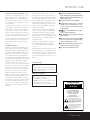 3
3
-
 4
4
-
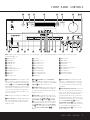 5
5
-
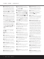 6
6
-
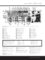 7
7
-
 8
8
-
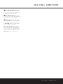 9
9
-
 10
10
-
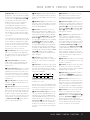 11
11
-
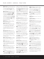 12
12
-
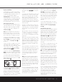 13
13
-
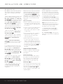 14
14
-
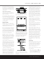 15
15
-
 16
16
-
 17
17
-
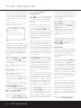 18
18
-
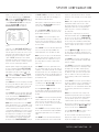 19
19
-
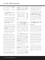 20
20
-
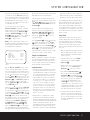 21
21
-
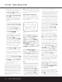 22
22
-
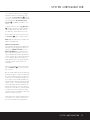 23
23
-
 24
24
-
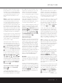 25
25
-
 26
26
-
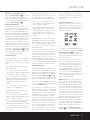 27
27
-
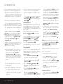 28
28
-
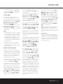 29
29
-
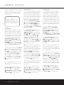 30
30
-
 31
31
-
 32
32
-
 33
33
-
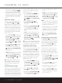 34
34
-
 35
35
-
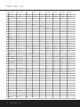 36
36
-
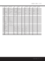 37
37
-
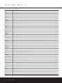 38
38
-
 39
39
-
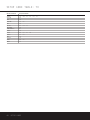 40
40
-
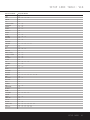 41
41
-
 42
42
-
 43
43
-
 44
44
-
 45
45
-
 46
46
-
 47
47
-
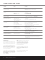 48
48
-
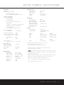 49
49
-
 50
50
-
 51
51
-
 52
52


Harman Kardon AVR 230 Owner's manual
- Category
- AV receivers
- Type
- Owner's manual
Ask a question and I''ll find the answer in the document
Finding information in a document is now easier with AI
Related papers
-
Harman Kardon 418 User manual
-
Harman Kardon AVR 245 User manual
-
-
-
-
-
-
-
-
Other documents
-
JBL AVR480 User manual
-
AKG AVR 135/230 Datasheet
-
 Pacific Digital AVR 635 User manual
-
Harman-Kardon AVR 147 User manual
-
Harman/Kardon AVR 156 Owner's manual
-
-
-
-
-
jWIN JS-P905 User manual
