Installation Instructions
6
&211(&7,1*7+('5<(572+286(9(17
RIGID METAL TRANSITION DUCT
• For best drying performance, a rigid metal transition duct is
recommended.
•
Rigid metal transitions ducts reduce the risk of crushing and kinking.
8//,67(')/(;,%/(0(7$/6(0,5,*,'75$16,7,21'8&7
,IULJLGPHWDOGXFWFDQQRWEHXVHGWKHQ8/OLVWHGÀH[LEOH
metal (semi-rigid) ducting can be used (Kit WX08X10077).
1HYHULQVWDOOÀH[LEOHPHWDOGXFWLQZDOOVFHLOLQJVÀRRUVRU
other enclosed spaces.
7RWDOOHQJWKRIÀH[LEOHPHWDOGXFWVKRXOGQRWH[FHHGIHHWP
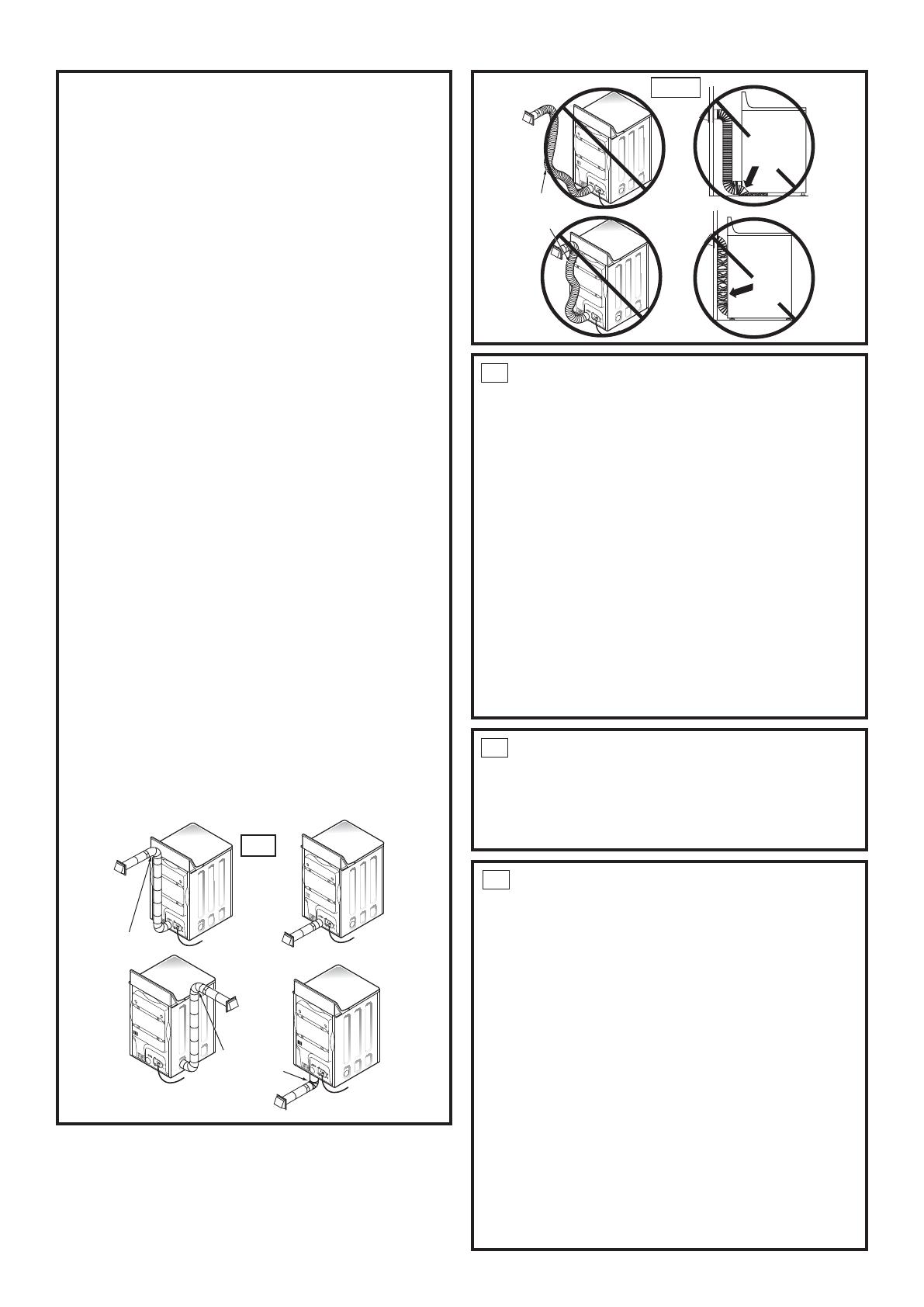
• For many applications, installing elbows at both the dryer
and the wall is highly recommended (see illustrations below).
Elbows allow the dryer to sit close to the wall without kinking
and or crushing the transition duct, maximizing drying
performance.
• Avoid resting the duct on sharp objects.
8//,67(')/(;,%/(0(7$/)2,/7<3(75$16,7,21'8&7
• In special installations, it may be necessary to connect the
GU\HUWRWKHKRXVHYHQWXVLQJDÀH[LEOHPHWDOIRLOW\SHGXFW
$8/OLVWHGÀH[LEOHPHWDOIRLOW\SHGXFWPD\EHXVHG21/<
LQLQVWDOODWLRQVZKHUHULJLGPHWDORUÀH[LEOHPHWDOVHPLULJLG
ducting cannot be used AND where a 4” diameter can be
maintained throughout the entire length of the transition duct.
,Q&DQDGDDQGWKH8QLWHG6WDWHVRQO\WKHÀH[LEOHPHWDOIRLO
type) ducts that comply with the “Outline for Clothes Dryer
Transition Duct Subject 2158A” shall be used.
1HYHULQVWDOOÀH[LEOHPHWDOGXFWLQZDOOVFHLOLQJVÀRRUVRU
other enclosed spaces.
7RWDOOHQJWKRIÀH[LEOHPHWDOGXFWVKRXOGQRWH[FHHGIHHWP
• Avoid resting the duct on sharp objects.
• For best drying performance:
1.
Slide one end of the duct over the clothes dryer outlet
pipe.
2.
Secure the duct with a clamp.
3.
With the dryer in its permanent position, extend the duct
to its full length. Allow 2” of duct to overlap the exhaust
SLSH&XWRȺDQGUHPRYHH[FHVVGXFW.HHSWKHGXFWDV
VWUDLJKWDVSRVVLEOHIRUPD[LPXPDLUÀRZ
4.
Secure the duct to the exhaust pipe with the other clamp.
ELBOWS HIGHLY
RECOMMENDED
ELBOW HIGHLY
RECOMMENDED
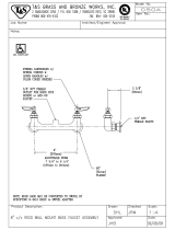
DO
DO NOT
SIT DRYER
ON FLEXIBLE
EXHAUST
DO NOT USE
EXCESSIVE
EXHAUST
LENGTH
DO NOT
CRUSH
FLEXIBLE
EXHAUST
AGAINST
WALL.
DON’T
9
$/&29(25&/26(7,167$//$7,21
• If your dryer is approved for installation in an alcove or closet,
it will be stated on a label on the dryer back.
• The dryer MUST be vented to the outdoors. See the (;+$867
INFORMATION section.
• Minimum clearance between dryer cabinet and adjacent
walls or other surfaces is:
0 in. either side
3 in. front and rear
0LQLPXPYHUWLFDOVSDFHIURPÀRRUWRRYHUKHDGFDELQHWV
ceiling, etc. is 52 in.
• Closet doors must be louvered or otherwise ventilated and
must contain a minimum of 60 sq. in. of open area equally
distributed. If the closet contains both a washer and a dryer,
doors must contain a minimum of 120 sq.in. of open area
equally distributed.
• The closet should be vented to the outdoors to prevent gas
pocketing in case of a gas leak in the supply line.
• No other fuel-burning appliance shall be installed in the same
closet with the dryer.
11
MOBILE OR MANUFACTURED HOME INSTALLATION
• Installation must conform to the MANUFACTURED HOME
&216758&7,216$)(7<67$1'$5'7,7/(3$57
or, when such standard is not applicable, with AMERICAN
1$7,21$/67$1'$5')2502%,/(+20(12%.
• The dryer MUST be vented to the outdoors with the
termination securely fastened to the mobile home structure.
(See (;+$867,1)250$7,21 section 6.)
• The vent MUST NOT be terminated beneath a mobile or
manufactured home.
• The vent duct material MUST BE METAL.
• .,7'0867 be used to attach the dryer securely to
the structure.
• The vent MUST NOT be connected to any other duct, vent, or
chimney.
• Do not use sheet metal screws or other refastening devices
which extend into the interior of the exhaust vent.
• Provide an opening with a free area of at least 25 sq. in.or
introduction of outside air into the dryer room.
• Stacking of a gas dryer is not permitted in a mobile home or
manufactured home.
10
BATHROOM OR BEDROOM INSTALLATION
• The dryer MUST be vented to the outdoors. See (;+$867
INFORMATION section 6.
• The installation must conform with local codes or, in the
absence of local codes, with the 1$7,21$/)8(/*$6&2'(
$16,=