Page is loading ...

I
I
TEK
CUSTOMER
PRODUCT
SERVICING
INFORfylATION
iublished by Tektronix Service
ldministrative Support
Syrac"Use
" I
Albuquerque
COMMITTED
TO
EXCELLENCE

Service Admin1strat1ve Support
October,
1883
laaue
31
)
)
)
TABLE
OF
CONTENTS
DAS9100
CIRCUIT
BOARD
PACKAGING
•.....••.•
DC5090/DC510
MICROPROCESSOR
RESET
CYCLER
••..
IDD
TOUCH-UP
PAINT
PART
NUMBERS:
OLD/NEW
COLORS
•.
Jl6
OPERATING
HINTS
••••...••
. . . 1
. . . . . 1
. . . . . . 1
OF150
LINE
FUSE
FAILURE
MOD
•.••.•
.
..
. . . .
. . . . 2
. . . 4
PORTABLE
CARRYING
STRAP
NOW
AVAILABLE
••
P6131
MANUAL
CORRECTION
P/N
070-4210-00
•.
S3200
RACK,
EQUIPMENT
SLIDE
ASSEMBLY
EXTENDER.
S3200
SAFETY,
FRONT
PANEL
LINE
VOLTAGE,
M46259.
S3200
SERIES
SITE
LOG
BOOK,
062-7232-00
•...•
S3200
2943/2944
CORRECTION
FOR
SIGNAL
EDGE
JITTER
.
TDC1/TDC2
MANUAL
CHANGE
•
TDCl/2
SPURIOUS
OUTPUT
..••.•
TV
LINEARITY
GRATICULES
..•...
TV
MANUAL
REVISIONS
(JUNE,
JULY)
TV
MANUAL
REVISIONS
(AUGUST)
••••
7L14
A48A5
U1755
REPLACEMENT
..•
50M40
WRONG
RESPONSE
TO
11
CONFIGURE?
11
COMMAND.
401X
OPTION
22/23
INSTALLATION/REPLACEMENT
CHANGES
•••
463X
HARD
COPY
MOTOR
IMPROVEMENTS
•••••.••
468
NEW
FAN
FILTER
REDUCES
OPERATING
TEMPERATURE.
. . . . . 4
5
• • 6
. . . 6
• • 7
• • 8
. . . . 5
. .
.10
. •
.10
.12
. . . .
.12
.
.13
. .13
. .
.13
. . . . .14
. . . .14
.14
613
HIGH
VOLTAGE
MODIFICATION
#50474
•.•••••
670/A,
671A,
672
COLOR
TEMPERATURE
MOD.
. • • •
.15
690SR/6942
HV
POWER
SUPPLY
FAILURE
••
834
POWER
SUPPLY
AUDIBLE
NOISE
••••••
1450
RF
LEVEL
INDICATION
•••.•..••
1502/1503
DEFECTIVE
CHART
RECORDER
PAPER.
1800
SERIES
TEST
STATION,
SIGNAL
SENSE
CARD,
MANUAL
CORRECTION.
1910
+5V
POWER
SUPPLY
FAILURES.
1980
PRINTER
PATCH
•••.•
~2465
INOPERATIVE
SWEEP
••••.
4010-1
NOISY
HARD
COPY
FIX
••••
4016-1
POWER
CORD
HOLDER
HINT
•
. . . .
.15
. . .
.15
• •
.15
. . . .
.16
. . . .
.16
.
.17
. . . . .
.17
. . . . . . .18
. . . . . .18
. . . . .
.19

)
)
)
Service Administrative Support • October,
1883
laeue 31
4027/27A
RELIABILITY
MODS
TO
DEFLECTION
BOARD
••••••.•••••••••
19
4052/4052A/4054/4054A
FIRMWARE
INFORMATION
••••••..••.•••••.•
20
4054/4114/4016-l/GMA101A/GMA102A/GMA125/618
POWER
SUPPLY
INTERCONECT
CABLE
MODI
FI
CATION.
• • • • • • • • . • . • • • . • • • • • • • . • . . • . • . • .
20
4110/4112A/4113A/4114A
FLEXIBLE
DISK
DRIVES
TWO
WIRE
STRAPS
•••.•.•••
22
4110/4112/4113/4114/4112
4113A/4114A/4116A
PROCESSOR
BATTERY
MOD
511340
••
24
4113A
OPTION
9
045-0054-00
UPGRADE
KIT
•••••••••
~
•••••.••..
24
4114/4114A/4114A30/4116A/4116A30
DISPLAY
CONTROLLER
SHORT
VECTOR
MOD.
•
.25
4691
INSTALLATION
AND
SPIRAL
HOSE
DISPOSITION
•••
• . • .
25
4691
LOW
INK
LEVEL
DETECTION
ADJUSTMENT
• . • • • • • . • • • . . • • .
.2b

)
)
)
Service Administrative Support
DAS9100
CIRCUIT
BOARD
PACKAGING
Affected instruments:
All
DAS
Circuit
Boards.
A shipping
package
is
now
available
in
which
DAS
circuit
boards
can
be
reliably
transported.
It's
part
number
is 004-2181-00.
It's
dimensions allow
packaging
of a
circuit
board
that is
17"
x 7.5"
which
is
the size of
DAS
plug
in
modules.
This
package
could also
accommodate
many
MDP
and
IDD
circuit
boards.
w2
Issue
13-21
DC5090/DC510
MICROPROCESSOR
RESET
CYCLER
serial
Numbers
Affected:
All
The
following
procedure
can
be
very
useful
for
cycling
microprocessor
based
instruments
with
intermittent
kernal
problems.
GPIB
instruments
that
support
the
•TEST• command
may
not
always
perform
a
complete
power-on
self
test.
From
time
to
time
it
may
be
useful
to
cycle
a
uP-based
instrument
at
a
rate
much
faster
than
the
fifteen
minutes
of
a
typical
cycler.
This
set-up
is
a
convenient
way
of
doing
it
and
requires
only
a TGS0l
(or
other
clock)
and a DDS0l.
Connect
the
trigger
output
of
the
TGS0l
through
a
cable,
terminator,
and
dual
input
coupler
to
the
inputs
of
the
OD501.
Connect
the
output
of
the
DO501
without
a
terminator
through
a
cable
and
BNC-to-Ez
Hook
adapter
to
the
reset
pin
of
the
uP
in
the
instrument
under
test.
-1-
October,
1983
laaue 31
Set
the
TGS0l
to
1
ms
and
trigger
the
DDS0l.
The
events
delay
count
switches
will
now
control
the
time
between
resets
from
zero
to
99
.999
seconds,
in
1
ms
increments.
w2
Issue
13-16
IDD
TOUCH-UP
PAINT
PART
NUMBERS:
OLD/NEW
COLORS
Approximately 3 years
ago,
IDD
changed
the colors of
their
products. This
has
caused
some
confusion
in
determining
which
products
have
the old colors
and
which
products
have
the
new
colors.
The
following are three
lists,
one
listing
the
IDD
products
having
the
Tek
blue color, the
second
listing
the
!DD
products
having
the old gray/tan colors
and
the third
listing
the products
having the
new
gray/tan colors.
Included with
each
list
of products are
the correct color
names
and
Tek
part
numbers
of the
13
oz. cans of spray
touch-up paint for
each
color.
Tek
Blue
Colored
IDD
Products
Tek
Blue
spray paint p.n.
252-0092-02
Tek
21
Tek
31
603
604A
606
607A
608
620
624
634
Tek
Old
Gray/Tan
IDD
Products
TV
Gray
spray paint p.n.
252-0217-
03
Tek
Tan
spray paint p .n.
252-0203-
04
(ARTICLE
CONTINUED
ON
THE
NEXT
PAGE)

Service Administrative Support
IDD
TOUCH-UP
PAINT
PART
NUMBERS:
OLD/NEW
COLORS
(CONT.)
4006
401X
402X
405X
4081
4601
461X
4623
463X
464X
466X
4905
4907
4923
4924
4952
4953
4954
4956
Tek
New
Gray/Tan
IDD
Products
Slate
Gray
spray paint p.n.
252-0728-00
Smoke
Tan
spray paint p.n.
252-0727-00
ADSOl
4925
41XX
4926
4691
4932
4695
4970
w2
Issue
13-20
Jl6
OPERATING
HINTS
REF:
Jl6
Manual
070-1879-00
The
following
article
provides
some
helpful hints for
use
of the Jl6.
This
infomation
can
help the
technician achieve
more
accurate
and
repeatable results
when
adjusting the
color temperature
on
color picture
monitors.
J16
Photolleter
Operating
Reca.endations
Many
engineering
and
manufacturing
areas are using
Tek
Jl6
photometers
for
measuring
CRT
luminance
and
setting color balance of white
fields.
I
have
observed several
problems
which
seem
to
reoccur.
The
following are
some
reconnendations regarding the
correct or
at
least
improved
techniques for
making
these
measurements:
-2-
October,
1883
laeue
31
1)
Zerofng--This fs
undoubtedly
the
greatest single
cause
of errors with
the Jl6
and
can
occur with
any
of the
probes.
Due
to variations in silicon
input bias current, the zero should
always
be
rechecked
when
changing
probes
and
when
the photo-diode
temperature changes.
This
fs
most
noticeable
on
r.t.
powered
Jl6
1
s
where
the photo-diode
is
positioned directly
over the r.t,
power
supply
when
plugged
into the top of the
Jl6.
Also
when
using the r.t,
power
supply, continuous
operation or
at
least
1/2 to 1
hour
wamup
is
best to
minimize
zero
drift
on
the
most
sensitive ranges.
The
Jl6
uses
a
mono-polar
DVM
circuit
which
will
still
read
000
even
when
the zero
is
offset in a negative
direction.
This
has
the appearance of
non-linearity especially
at
low
light
levels.
Also
the
same
reading will
not
be
obtained
when
changing
to the
next range.
To
let
the operator
know
that
it
fs incorrectly zeroed, the
minus
sign fs
wired
to indicate that
the zero fs
offset
in a negative
direction.
To
correctly zero the
Jl6,
cover the sensor
and
adjust the zero
adjustment
on
the
O.lX
range
until the
minus
sign
just
flickers
on
and
off.
An
alternate aethod fs to adjust the
zero until a reading of typically 5
fn
the
last
place dfgft fs obtained.
This
reading fs
checked
often
when
using the
most
sensitive ranges.
If
the Jl6 zeros correctly
on
the
XO.l
range
but fs incorrect
on
the
XlOOO
range,
ft
fs
an
fndfcatfon
that
the
internal
DVM
zero
needs
readjustment
according to the procedure
fn
the
manual.
The
zero procedure fs
more
complex
when
using the
J6523
1
luminance
probe--enough
so
that
I
reconnend
use
of the
Minolta
1 spot meter,
ff
possible, rather than the Jl6/J6523.
The
Minolta
has
auto ranging.
no
zeroing required,
compact
size
and
a
display that fs visible
through
the
eyepiece
used
for sighting.
The
(ARTICLE
CONTINUED
ON
THE
NEXT
PAGE)
)
)

Service Administrative Support
)
)
)
Jl6
OPERATING
HINTS
(CONT.)
trade-off fs a poorer spectral
match
to the
CIE
photopfc
response curve.
To
correctly zero the J6523/Jl6
combfnatfon, cover the
J6523
objective
lens
and
adjust the
J6523
zero
on
the
XlOOO
range.
Then
change
to the
XO.l
range
and
adjust the Jl6 zero.
It
fs
usually necessary to repeat the
procedure
once
or
twfce
as
the
adjustments interact.
There
fs
an
incompatabilfty
between
the
J6523
and
very
early
Jl6's
that prevents zeroing
on
the
XlOOO
range. A
simple
mod
kit
fs available to cure
ft.
The
kft
P/N
fs
040-0746-00,
and
applies to the
Jl6's
below
S/N
8052000.
2)
Calf
bration--The photopfcally
corrected J16
probes
are
all
initially
calibrated
fn
the plant
usfng
3000
K
tungsten-halogen white
light
source.
For
maximum
accuracy
with
CRT's
they
should
be
calibrated for the
individual
phosphors
to
be
measured.
Correction factors
up
to approximately
101
(higher for the Mfnoltas)
may
be
necessary to obtain correct data
due
to devfatfons
from
the photopic
response curve.
Thfs
fs
most
severe
in the
red
and
blue regions
where
a
small
absolute deviation
can
be
a
large percentage of the actual value
due
to
it
befng
on
the
lower
skirts
of
the photopfc response curve.
Electrical Standards
can
provide thfs
calibration service.
·
The
long
tenn calibration of the
probes
fs
very
stable
due
to the
sflfcon
photodfode
and
glass photopic
correction
filters.
Sfnce
the Jl6
itself
fs calibrated
usfng
only
a
simple current source
and
DVM,
ft
fs
seldom
a source of error unless
incorrectly zeroed.
I
rec01111end
that
the J16's
be
recalibrated about
once
a year.
The
probes
probably
should
be
recalibrated
every sfx
months
or so--110stly
because
calibration techniques are
being
improved
with
time
rather
than
the
likelihood of the
probes
themselves
-3-
October,
1883
laaue 31
changing
calibration.
Routine
Jl6
and
probe
calibration
is
handled
through
Factory Service while special
probe
calibrations are
done
by
Electrical
Standards.
3)
J6503
Modifications--As
assem"bled,
the J6503
has
a plastic
window
and
shiny blue plastic
front
which
can
cause
minor
reflections
when
placed directly
in contact
with
a
CRT
faceplate.
For
best accuracy the plastic
window
should
be
discarded, the
probe
front painted
flat
black
and
the
probe
recalibrated.
Some
early J6503's
had
glossy black
paint
on
the internal baffles
and
no
inner black shield to
reduce
internal
reflections.
This
resulted in side
lobes
and
a significant difference
fn
readings
with
and
without the
light
occluder often
used
for
CRT
measurements.
These
can
be
modfffed
and
recalibrated without
too
much
df
ffi
cul
ty.
4)
2 1/2 Dflft Jl6's--Early
Jl6's
having
only
1/2
digits are
dffffcult
to
read
accurately,
when
the reading
are
at
•20
11
or
so
as
the
+l
dfgft
ambfgufty
amounts
to
51.
-Also they
have
a
12Hz
count rate rather than 6
Hz
as
fn
the 3 1/2 dfgft version.
Thfs
causes the display to
change
faster
than
the user
can
detect a
reading for varying lfght fntensftfes.
Both
of these
shortcomings
were
addressed
with
major
modfffcations
at
S/N
8052000.
5)
N:.
Versus
Battery Operatf on--
The
Jl6 fs available
with
an
Ar.
power
supply installed as
Option
3 or
ft
may
be
ordered separately to replace the
battery
pack
as
119-0404-00.
Thf
s
overcomes
three problems--
I) Battery
lffe
fs short
and
recharging
tfme
is
long,
(ARTICLE
CONTINUED
ON
THE
NEXT
PAGE)

Service Administrative Support
Jl6
OPERATING
HINTS
(CONT.)
2)
the charging current
is
1/3
of the operating current;
thus,
use
of the charger
during operation will not
siginificantly
increase
operating time,
and
3)
the
Jl6
zero will
be
most
stable
on
the higher
sensitivity
ranges
when
operated continuously.
Also, the early
Jl6's
used
a three
pin battery charger plug
that
had
no
strain
relief
and
often
had
the
wires short or break
unbeknownst
to the user.
In
conclusion, recent
Jl6's
are
quite stable
and
should
have
good
correlation
between
individual
units
if
zeroed
and
calibrated
correctly. Older
Jl6's
can
be
brought
up
to date
relatively
easily.
w2
Issue
13-18
OF150
LINE
FUSE
FAILURE
MOD
REF:
M51508
As
a
result
of the excessive
number
of
line fuse
failures
caused
by
high
transient
voltages
from
the
AC
line,
a
Metal
Oxide
Varistor (307-0415-00)
has
been
added
to the
power
supply in
parallel
with the spark
gap
A30A2E2010.
To
install
the Varistor, incapsulate
it
in shrink tubing (162-9031-00), lay
it
on
top of
A30A2C2010,
and
solder
the Varistor's leads to the spark
gap
leads.
w2
Issue
13-18
-4-
October,
1983
la-,•
31
PORTABLE
CARRYING
STRAP
NOW
AVAILABLE
A
new
style
carrying strap
is
now
available,
P/N
346-0199-00.
It
was
designed for
use
with the 2213/2215's,
but
can
be
used
with
any
portable
instrument having a standard
adjustable carrying handle,
such
as
the
400/300
series
and
2300
series.
The
illustration
below
shows
typical
mounting
and
use.
.TYPICAL
MOUt,mw;
Of
CAM.'tlWG
SlMP
TO
HANDLE
I -
---
MCNE
HANO
LE
OVEP.
OWE
POS\T
ION
FOR
EASE
WliEN
CARI\'(
\WC.
w2
Issue
13-17
)!
)

)
)
)
Service Administrative Support
October,
1983
laaue 31
P6131
MANUAL
CORRECTION
P/N
070-4210-00
TDC1/TDC2
MANUAL
CHANGE
RE:
TDC1/TDC2
Manual
070-2754-00
On
Page
6-4
of
the
P6131
Manual,
Figure
1,
Index
fl,
the
comp
box
for
the
3
Meter
Probe
is
incorrectly
listed.
It
should
be
P/N
206-0282-00,
not
206-0283-00.
Below
i~ a
manual
correction
for
the
TDC1/TDC2
Instruction
Manual
that
deals
with
specification
changes
for
the
re-
quired
test
equipment.
w2
Issue
13-16
TEITRONII
MANUALS
CHANGE
INFORMATION
Date;
Product;
Manual
Part Ho,;
Change
Bererenae;
7/]3/83
TDC1/TDC2
070-2754-00
CS/783
DESCRIPTION
w2
Issue
13-16
•======================================================================
TEXT
CHANGES
SECTION
4
CALIBRATION,
TABLE
4-1,
TEST
EQUIPMENT
REQUIRED,
me.
.4.:Z
CHANGE
TO
READ:
ITest Modulator
I
I
I
I
I
I
I
I
I
0.1
dB
Flatness
within
channel
limits
and
phase
noise
less
than
0.2
degrees
rms.
Signal
Generator
to
drive
Test
Modulator
100
MHz
to
1000
MHz
with
typical
sideband phase
a
noise
or
at
least
-70
dBc
at
100
Hz rrom
the
oarrier
as
measured
in
a 1 Hz bandwidth.
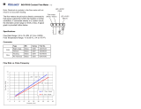
Performance
Check
and
Adjustment
Tektronix
Part
No.
067-
0886-00
---------------------------------------------------------------------------
a
dBc
=
dB
rererenoed
to
carrier
PERFORMANCE
CHECI,
STEP,_
part
a,
Page
J&-16
CBAJIGE
TO
READ:
••
Rerer
to
Fig.
JJ-9. Drive
the
teat
1t0dulator
with
a
linearity
stairoaae
signal
trom a video
test
signal
generator
such
aa
a
TEICTRONII
1,10/TSG3/SPG combination. Conneot
the
low
phase noise
signal
generator
to
the
teat
IIOdulator
ext
lo
input.
Connect
the
teat
modulator
rt
output
to
the
1,so-1
(SYSTEM)
rt
input,
and
make
the
appropriate
tront-panel
oonnectiona
on
the
1,so-1
to
oomplete
the
SYSTEM.
-5-

,I
ii'
1il1
Service Administrative Support
S3200
RACK,
EQUIPMENT
SLIDE
ASSEMBLY
EXTENDER
REF:
2943/2944
Clock
Generator
070-3335-00
2941
Clock
Generator
070-3126-00
Rll40
Programnable
Power
Supply
070-3108-00
Rl340
Data
Coupler
070-3107-00
The
part
number
for the
equipment
slide
assembly
extender
is
407-1577-00.
The
407-1577-00
is for a
pair of extenders,
left
and
right
side.
These
extenders are 3.56 inches
wide
and
6 inches long.
The
extenders
are included
as
a
sub
part for the
slide
assembly
351-0085-00.
Normally
there should
be
no
need
to order the
extender separately.
The
exception to
this
is
when
the extender is
damaged
or a rack
mounted
equipment
is
bought
outside Tektronix,
i.e.
DEC
RK05
disk
drive.
The
extender
may
be
needed
because the
slide
assembly
supplied
with other
vendor
equipment
is
usually
too short for the racks
used
in the
S3200
series
system.
Slide
Assembly
351-0085-00
Extender
P/N
407-1577-00
w2
Issue
13-20
-6-
October,
1883
laaue 31
S3200
SAFETY,
FRONT
PANEL
LINE
VOLTAGE,
M46259
Reference:
2942,
2943,
2944,
Rl340
Series,
1140
Series,
and Rl330
Series
instruments.
Line
voltages
are
accessible.
These
changes
protect
the
service
technician
from
exposure
to
dangerous
line
voltages.
Install
mounting
plate,
switch
cover,
and
appropriate
hardware
over
toggle
switches
contained
on
the
inside
of
the
front
panels
on
the
above
referenced
instruments.
For
the
2942
only,
remove
a
section
from
the
right
subpanel
(386-3241-00)
to
prevent
pinching
wires
when
incorporating
the
switch
cover
change.
2942
Pattern
Generator
Only:
Remove: 1
ea.
386-3241-00
Subpanel,
front
right
Add: 1
ea.
386-3241-01
subpanel,
front
right
All
Others:
2
ea.
211-0097-00
Screw,
mach.
4-40
x
0.312
1
ea.
337-3064-00
Shield,
SW
poly
carb
1
ea.
386-4942-00
Plate,
mounting
2
ea.
129-0304-00
Spacer
post,
l.265L,
w/4-40
TBD
Add: 2
ea.
211-0097-00
Screw,
mach.
4-40
x
0.312
2
ea.
129-0304-00
Spacer
Post,
1.265L,
w/4-40
TBD
(ARTICLE
CONTINUED
ON
THE
NEXT
PAGE)
))
)

Service Administrative Support
)
)
)
S3200
SAFETY,
FRONT
PANEL
LINE
VOLTAGE,
M46259
(CONT.)
1
ea.
386-4942-00
Plate,
mounting
1
ea.
337-3064-00
Shield,
SW
poly
carb.
No
update
modification
kit
is
available
for
the
change.
Discrete
parts
must
be
ordered.
This
modification
will
also
protect
against
electrical
shorting
of
AC
voltages
to
extended
circuit
boards.
w2
Issue
13-16
S3200
SERIES
SITE
LOG
BOOK,
062-7232-00
The
Site
Log
Book
provides maintenance
personnel with
one
common
place to
record
S3200
Series
Semiconductor
Test
System's information.
All
S3200
Series system
models
may
use
the Site
Log
Book.
A
new
Site
Log
Book
is
recommended
annually for
each
system.
SECTION
DESCRIPTIONS
The
Site
Log
Book
is
divided into
eight
major
sections.
Each
section
will contain documentation concerning
one
specific
area of
system
information.
Section I - Information
The
information Section
identifies
personnel for maintenance,
repairs,
or
other system
responsibilities.
Section II -
Logs
The
Logs
Section
is
for recording
system maintenance or repair
calls.
This section also contains Service
Logs,
which
should
be
completed
for
-7-
October,
1983
laaue
31
each
service
call.
Documentation
related to system performance is also
included
under
Uptime
Calculation.
Section
III
- Schedules
The
Schedules Section contains several
types of
forms
to
assist
in
documenting
and
scheduling
maintenance.
The
Schedules Section
should
be
reviewed
soon
after
the
system
is
installed.
Prior to
finalization
of a maintenance plan,
all
sections should
be
compared.
This
comparison should
be
done
to
check
for
conflicts
in scheduling. Different
maintenance services should not
be
scheduled simultaneously.
Section
IV
- Configuration
The
Configuration Section provides
worksheets for system inventory.
The
System
Inventory
is
broken
into basic
categories. Tektronix products
and
options are separate
from
computers
and
peripherals.
The
OEM
portion
lists
many
products not manufactured
by
Tektronix
that
may
be
placed
in
an
S3200
Series
System.
Section V - Software
The
Software Section
is
a very
important part of the Site
Log
Book.
Because
of
its
importance, the four
portions of
this
section should
be
kept current at
all
times. Software
modifications, updates,
and
changes
should
be
documented
in
this
section.
A system
CONFIG.EDT
listing,
a
copy
of
the
System
Formatter,
and
a
copy
of
the
System
Disk
directory are located
in the Software Section.
Section
VI
- Site Spares
System
spares provide additional
support at the
system
site.
The
Site
Spares Section provides
Log
Out
Sheets
and
inventory forms.
Users
may
desire
to
use
their
own
forms
or
methods
to
meet
their
needs.
(ARTICLE
CONTINUED
ON
THE
NEXT
PAGE)

Service Administrative Support
S3200
SERIES
SITE
LOG
BOOK,
062-7232-00
(CONT.)
Section
VII
-
General
Additional
system
information
may
be
I
filed
in
this
section.
,1,,1
1
11
j Section
VIII
- Service
Records
The
last
section of the Site
Log
Book
may
be
used
to
file
Service Records.
w2
Issue
13-20
S-3200
2943/2944
CORRECTION
FOR
SIGNAL
EDGE
JITTER
Ref:
2943/2944
Manual,
P/N
070-3335-00
Mod
#50198
Wizard's
Workshop,
Issue 13-8,
April
15,
1983,
Pg.
9,
S-3200
2943/2944
Clock
Standardization
Mod
#M45157.
In
some
2943/2944
clock generators the
clock signal
edges
may
vary
(jitter)
between
400
ps
to 1 ns.
The
jitter
is
caused
by
high signal
impedance,
signal sources
and
cross
talk
to
adjacent signals.
The
solution
is
to decrease source
impedance
to increase the drive
current.
This
will
stabilize
the
signal
and
reduce cross
talk
effects
•.
On
the
Cycle
Length
Board
670-5383-05
change
Rll3,
R114,
Rll5, Rll6,
R132,
Rl33
from
1.BK
P/N
315-0182-00
to a
270
ohm
P/N
315-0271-00.
Change
board
P/N
to 670-5383-06.
On
the
Clock
Phase
Board
670-5425-01
change
R300
and
R301
from
a
1.5K
ohm
P/N
315-0152-00
to a
270
ohm
P/N
315-0271-00,
change
board
P/N
to 670-5425-02.
On
the
Programned
Cycle
Board
670-5417-01
change
R211
and
R212
from
1.8K
ohm
P/N
315-0182-00
to
270
ohm
P/N
315-0271-00,
change
board
P/N
to 670-5417-02.
The
following are locations of the
changes
on
partial
drawing
of
schematic
and
parts layout:
-8-
'•
'
•
7
October,
1983
laaue 31
C:V~LE
CYC.L&.
PR£-'T~
PRE·T~
T~
~
T¢
0
c.1i
•
..,se.
~-
;a?o.11.
C.P.£.
CT.i:".
~
01'1/
~
~
CLOt.K
J
[]
670-5383-06
P4
Cycle
Length
s,s
I
I
""0
C.
YC.~i;
Bu~
B17
..
.e
I
..
2~
\ ,-o
.;2q
..
,s
I
A13
I
TO
.JC."7
89
I
TO
J"!.18
••
\
..,
I
TO
C.P.£.
BU~
81~
I
111!
I
'TO
.J'31
.J
I
TO
C.1-0C.k.
BU~
,.n
(ARTICLE
CONTINUED
ON
THE
NEXT
PAGE)
)
)11

)
)
)
Service Administrative Support
S-3200
2943/2944
CORRECTION
FOR
SIGNAL
EDGE
JITTER
(CONT.)
••"•
ca.aao
l,t,
...
WID'TH
u1.a,~NI,
....
111a•
PIN6
~-
l
Ur:.
..
I
I
..
Ul9A
ltl
TlfRU
i?
tt•
Tlfll:U
.'7
Ut&D
~IN
l'I
"''"
•10
All
I
O.CH
-------+---·-·
•
!..lV
$
I
[J
1?_.,;o.,E
"'
!
AND
~flAt~
670-5425-02
PS
through
Pll
Clock Phase
l
it,;n
•10
-9-
14
AZ.IC
!UO
October,
1883
laaue 31
~.itV
llB'JI
oitO
ll812
,ao
s
o.,
g,
O;i,
Q5
•
5.Z.V
IS
it
'I
11.111
OitO
A.114
1&0
TIUGoG.ER
....
I
670-5417-02
Pl2
Progra11111ed
Cycle
(ARTICLE
CONTINUED
ON
THE
NEXT
PAGE)

11,
Service Administrative Support
S-3200
2943 2944
CORRECTION
FOR
SIGNAL
EDE
JI
TER
C
NT.
These
changes
should only
be
used
on
systems
that
have
had
the
2943/2944
Clock
Generator standardization
mod
installed.
There
are
040
kits
available to
install
the
standardization
mod.
The
kit
P/Ns
are
040-1110-00
for 7
Phase
systems
and
the
040-1111-00
for
14
Phase
systems.
With
the
2943/2944
standardized
any
standardized clock
is
a
direct
replacement without
having
a
major
reskew
or calibration of system.
Without
standardization replacing
any
part or
all
of the clock
my
require a
major
reskew
or calibration of
systems.
w2
Issue
13-19
TDCl/2
SPURIOUS
OUTPUT
REF:
TDCl/2
Instruction
Manual
070-2754-00
SAR
#05211
A recent inquiry
from
the Field
questioned the presence of a spurious
signal at about
31
MHz
when
the
TDC2
was
tuned to
Channel
69
or
70.
This
spur
was
about
-30
down
from
the
fundamental
which
gave
a
total
of
about
-80dBm.
In
either
case,
it
was
judged to
be
worse
than other units
(TDC2's)
under
similar conditions, but
was
not
out of specs.
One
of the
problems
encountered in
making
this
measurement
centered
around
the
067-0886-01
Test Modulator.
The
signal
coming
out of
RF
OUT
is
spec'd
at
-25dBm.
However,
due
to the
lack of
any
filtering
on
this
output,
harmonics generated
by
the
RF
Mixer
stage will
be
present.
In
the case of
Channel
69, the
second
Harmonic
would
be
at
2 X Visual
Carrier+
I.F.,
or 2
X (801.25 +
37)
or 1676.5
MHz.
October,
1883
la8&1e
31
If
one
assumes
no
harmonic
attenuation
out of
RF
OUT,
this
frequency (1676.5
MHz)
would
be
at
-25dbm
when
it
was
applied to the
TDC2,
and
would
mix
with the
first
L.O.
in the
TDC2.
Due
to the input
Bandpass
Filter's
image
rejection of
40dB,
the
first
Mixer
would
produce
a signal of
about
-65dBm
at
about 434.5
MHz.
Mixing
this
frequency with the
second
L.O.
(403.75
MHz)
will
produce
a signal at
30.75MHz,
giving
us
the presence of a
spur.
The
amplitude of
this
spur
is
dependent
upon
the
first
IF
Image
Rejection Ratio,
which
is spec'd
at
40dB
or greater for the
TDC2,
and
the
level of
harmonics
coming
out of the
Test Modulator,
which
are
not
spec'd.
-10-
Some
places to
look
for cures to
this
"problem"
are:
---Pay close attention to balancing
the
RF
mixer
in the Test
Modulator.
---Check cable dress in the
TDC2.
---Use care
when
adjusting the
Pin
Attenuator in the
TDC,
along
with the
Mixer,
Bandpass
Filter,
IF
Amp
other associated areas.
---Don't
use
the Test
Modulator
to
look
at
Image
Rejection.
Follow
the procedures in the
TDCl/2
manual.
w2
Issue
13-21
TV
LINEARITY
GRATICULES
REF:
650HR
Manual
070-2646-01
670A
Manual
070-2201-01
690SR
Manual
070-3821-00
When
adjusting the convergence of a
color monitor to
meet
specifications,
(ARTICLE
CONTINUED
ON
THE
NEXT
PAGE)

)
)
)
Service Administrative Support
,
TV
LINEARITY
GRATICULES
(CONT.)
one
is
faced with a variety of
linearity
graticules, color display
monitor types,
and
signal generators
to
make
a choice
from.
Besides
having
three sizes of
CRT's,
there are four
major
television standards,
non-television display applications,
and
more
than
18
signal generators
from
Tektronix alone.
This
list
is
further
expanded
when
one
considers
custom
modified products or
specification/standards changes.
This
article
will
mainly
touch
upon
standard applications,
however,
some
custom
units will
be
discussed
where
appropriate.
The
following
list
describes the
linearity
graticules currently
available for Tektronix
Color
Monitors.
In
general, these are
plastic
overlays that are designed to
be
placed in front of the
CRT.
A
small
high-intensity
lamp
1s
then
placed
at
a prescribed distance
from
the face of the
CRT,
thereby
projecting the
shadows
of the various
graticule
markings
on
to the
CRT
face.
Graticule
P/N
Instrument
TV
Stand.
331-0305-00
650
Series
NTSC,
SECAM,
PAL-M*
331-0359-00
650
Series
PAL
331-0305-01
670
Series
NTSC,
·PAL-M*
331-0359-01
670
Series
PAL
067-1054-00
690SR
NTSC*
067-1055-00
690SR
PAL
067-1034-00
690SR
Opt
40/48
Hi
Res***
067-1034-00
6942
Hi
Res***
/
3~1-0305-02-trtr
650,670,
NTSC,
1
690SR
PAL-M
331-0359-02**
650,670,
690SR
PAL
October,
1883
lae&1e
31
*
Some
TSG12
and
TSPll
generators
were
compatible
with
NTSC
Graticules
due
to
the
number
of horizontal
and
vertical lines used.
**
331-0305-02
and
331-0359-02
are
35rml
slides that are
meant
to
be
projected
upon
the
CRT
face with a slide projector
having
a lens of the proper
focal length.
By
carefully
positioning the projector,
these slides
can
be
used
with
any
display that
has
the
proper aspect
ratio
(3
to 4).
***
The
067-1034-00
graticule for
the
690SR
and
6942
is for
non-TV
displays using a
31
KHz
scan
rate
and
a special
generator.
-11-
In
general, those graticules that
are
used
for television
applications
have
patterns
designed for crosshatch
convergence
patterns of
two
types.
NTSC,
SECAM
and
PAL-Muse
a
14
x
17
line configuration, while
PAL
uses a
15
x
20
line configuration.
High
resolution graticules
such
as
the
067-1034-00
use
an
11
x
15
line configuration.
The
following
table
lists
convergence
generators
produced
by
Tektronix
and
provides
a
handy
ref~rence describing the
convergence line pattern that the
various instruments produce.
14 X
17
15
X
20
11
X
15
140
141A
Mod
431L
067-1039-00
142
141A
Mod
7032
143
141A
Mod
431S
144
141A
Mod
432D
145-M
145
(ARTICLE
CONTINUED
ON
THE
NEXT
PAGE)

Service Administrative Support
TV
LINEARITY
GRATICULES
(CONT,)
146
TSG12(*1)(*3)
TSG2(*3)
TSP11(*2)(*3)
TSP(*3)
TSG12
(
*l
)(
*3)
TSPll
(
*2
)(
*3)
TSP21(*3)
*l
TSG12's
produced
prior to
S/N
8011550
produced
14xl7
line
patterns. After
S/N
8011550,
the
TSG12
produced
a
15x20
pattern,
with
a 14xl7 line
pattern available through the
remote
connector. Consult the
product
manual
(P/N
070-2329-00) for further
details.
*2
TSPll's
produced
prior to
S/N
8011550
produced
14xl7 line
patterns. After
S/N
8011550,
the TSPll
produced
a
15x20
line pattern with
an
8xl0
pattern available through the
remote
connector. consult the
product
manual
(P/N
070-2664-00) for further
details.
*3
TSPl,
11,
21
and
TSG2
and
12
generators
have
the capability
of producing large or
small
square convergence patterns.
Refer to the product
manuals
for further
details.
TSPl
TSPll
TSG21
TSG2
TSG12
070-2621-00
070-2664-00
070-4569-00
070-2599-00
070-2329-00
From
the
two
tables
given
(above),
one
can
readily determine
which
linearity
graticule
is
needed
for
. the
particular
monitor
and
October,
1883
laeue 31
generator
that
is
available.
Convergence
can
be
accomplished
in
a
straight
forward
manner
using
the procedures outlined
in
the
display device manuals.
Close
attention to detail
is
reco11111ended,
with
particular
attention paid to the correct
physical placement of the
light
source
and
proper adjustment of
other
circuits
and
parameters
that
directly
or indirectly affect
convergence.
Some
of these are
horizontal
and
vertical
scan
size
and
linearity,
purity,
and
low
and
high
voltages.
-12-
w2
Issue
13-18
TV
MANUAL
REVISIONS
(JUNE,
JULY)
The
following
TV
product
manuals
were
updated/revised
as
of
June
and
July
1983.
June
Revisions
TDCl
and
TDC2
650HR
Seri
es
July Revisions
SPG1/SPG2
TSG5
69M41
070-2754-00
070-2646-01
070-2104-00
070-2336-00
070-2878-00
w2
Issue
13-18
TV
MANUAL
REVISIONS
(AUGUST)
The
following television product
manuals
have
been
revised/updated
as
of
August
1983:
1450,
1450-1
Instruction
Manual
P/N
070-2200-01
TSG
Instruction
Manual
P/N
070-3782-00
w2
Issue
13-21

)
)
)
Service Administrative Support
7Ll4
A48A5
01755
REPLACEMENT
RE:
M50713
On
the
Sununing
Amplifier
and
2nd
LO
Error
Amplifier
Board
A48A5,
if
the
-15V
supply
comes
up
before
the
+15V
supply,
the
current
limit
in
A48A5
01755
is
disabled
and
the
microcircuit
(P/N
156-0067-12)
becomes
inoperative.
To
prevent
the
destruction
of
A48A5
01755,
A48A5
Cl755
was
replaced
with
a
luf
capacitor
and
a lOOohm
resistor
was
added
in
series
with
the
-15V
line
to
A48A5
01755.
If
field
replacement
of
A48A5Ul755
becomes
necessary,
parts
replacement
kit
050-1781-00
will
provide
the
new
microcircuit
along
with
parts
and
instructions
for
installing
the
mod.
w2
Issue
13-16
50M40
WRONG
RESPONSE
TO
•CONFIGURE?•
COMMAND
Serial
Number:
8010100
to
8010310
Reference:
UllOl
To
correct for a possible erroneous
response to the
CONFIGURE?
query over
the
GPl8
buss
UllOl
was
reprogramed.
The
new
part
number
for UllOl
is
160-1479-01.
w2
Issue
13-19
401X
OPTION
22/23
INSTALLATION/REPLACE-
MENT
CHANGES
REF:
021-0201-00/01
2741
Correspon-
dence
Code
Interface Service
Manual,
p.n.
070-2280-0X
Reports
have
come
in
from
the
field
of
the
Option
22/23
interface being
DOA
on
installation.
This
would
normally
show
-13-
October,
1883
laaue 31
as
continual erasing of the screen
after
initial
powering
up
and
pressing
the
page
key.
Turning
power
off
and
then
back
on
will not clear the
problem
in
most
instances.
Investigation into
this
phenomenon
has
found
a
firmware
abnormality caused
by
changes to the
CMOS
RAM
mask.
This
firmware
abnormality will not
be
fixed.
The
reason for
this
failure
mode
has
been
found
to
be
incorrect
initial-
ization
and
set
up
parameters written
into the
CMOS
RAMs
by
virtue of the
particular
way
the
CMOS
RAM
initially
powers
up.
To
work
around
this,
the
installation
and
replacement procedures
must
be
changed.
Any
time
the Processor
board
is
installed
or replaced, the battery
backup
must
be
disconnected before
powering
up
the interface. This
is
easily
done
after
installing
the
interface
by
disconnecting JllO
on
the
processor board,
powering
up
the
terminal, typing page,
and
then
reconnecting JllO (without
powering
down)
onto the Processor board. This
procedure will ensure
that
the
menu
comes
up
and
set
up
parameters
can
be
set
correctly without
hanging
the
terminal in
an
erase
mode.
If
a unit requires service because
it
constantly
pages
when
the terminal is
turned
on
and
paged,
first,
turn off
the terminal
and
disconnect JllO
from
the Processor board.
Wait
at least
one
minute
for a
11
vo
1 tage potential
to drain
off,
then
power
up.
If
the
menu
does
not
come
up,
type
Break
1.
If
the
menu
still
does
not
appear,
then there is probably a
problem
with
the Processor board.
If
the
menu
comes
up,
then
check
the battery.
It
may
be
the cause fa the
problem.
Normal
battery voltage .should
be
be
approximately 2.9
volts.
w2
Issue
13-16

Service Administrative Support
463X
HARD
COPY
MOTOR
IMPROVEMENTS
Ref:
November
20,
1981
Wizard
Workshop
article
11
463X:
Hard
Copy
Unit -
Maintenance
of
D.C.
Motors"
The
1~7-0039-01
motors
used
in the
463X
dry
silver
t:opi
ers
have
recently
been
improved.
•
An
o-ring seal
is
now
being
used
around
the output shaft
of
the
gearhousing to
reduce
leakage of
lubricant.
• A thicker gearhousing
cover
is
also
being
used
to
reduce
leakage.
Some
motors
have
been
seen
with
two
of
the thinner covers ,
one
mounted
on
top
of
the other.
•
The
cut
on
the
wonn
gear
has
been
changed
to
reduce
heat
and
friction.
These
changes
to the
motor
do
not
affect
specifications, inventory,
documentation,
etc.
Therefore, the
part
number
of
the
motor
does
not
change.
The
effective
lot
code
for all the
above
improvements
is
LW
(December,
1983).
For
an
explanation of the
coding
of
these motors, please refer to
the
above
referenced
arti
cl_
e.
w2
Issue
13-21
468
NEW
FAN
FILTER
REDUCES
OPERATING
TEMPERATURE
Serial
Numbers:
All
Ref:
468
Service
Manual,
Vol.
II1
Figure
2-122
A new
Air
Filter
for
the
468
is
now
being
used
that
reduces
the
internal
ambient
temperature
by 4
degrees
Centigrade.
As a
result
of
the
decrease
in
temperature,
the
instrument
will
have
increased
reliability.
The
part
number
for
the
new
filter
is
378-2042-02.
-14-
October,
1883
laaue
31
PLAN
OF
ACTIOH:
All
old
filters
(378-2042-00)
are
to
be
purged.
Every
468
that
comes
in
for
service
either
under
warranty
or
billable
that
has
the
old
filter
is
to
have
the
new
filter
installed
at
no
cost
to
the
customer.
ROTE:
When
the
new
filter
is
installed,
it
is
possible
to
see
a
faint
image
of
the
fan
and
the
fan
mounting
screws.
When
the
denser
old
filter
is
installed,
nothing
can
be
seen
behind
it.
w2
Issue
13-17
613
HIGH
VOLTAGE
MODIFICATION
#50474
Customer
Serv~ce
has
implemented
a
modification to
613
high
voltage
boards
to
improve
reliability
and
performance.
As
a result
of
this
mod,
the
613
high
voltage
board
part
number
rolls
from
670-2308-06
to
670-2308-09.
The
restorer diodes
CR51
and
CR62
have
failed readily especially
when
being
soldered
with
a
high
wattage iron (see
reference
above
for
details).
To
correct
this,
their
part
number
is
being
changed
from
152-0242-00
to
152-0107-03.
The
high
voltage capacitors
Cl32, Cl41,
Cl42,
C151,
C152,
C161
and
Cl62
have
al
so
shown
poor
reliability.
On
occasion,
their
failure
has
destroyed a
CRT
by
producing
a
phosphor
burn. This
situation
is
improved
by
changing
the
part
numbers
of these capacitors
from
283-0101-00
to
283-0477-00.
The
-0477-
is
a distinctive blue capacitor similar
to those recently
modified
into the
611.
)J
w2
Issue
13-17

)
)
)
Service Administrative Support •
670/A,
671A,
672
COLOR
TEMPERATURE
MOD
REF:
SAR
#16778
670,
671,
672
Instruction
Manual
P/N
070-1445-00
670A,
671A
Instruction
Manual
P/N
070-2201-01
670-1
Series Instruction
Manual
P/N
070-1946-00
670A-l
Series Instruction
Manual
P/N
070-2202-00
Mod
5224-4
Recent
inputs
from
the Field
have
indicated
problems
concerning setting·
up
color temperatures in the
670
Series
Color
Monitors.
The
problem
centered
around
the proper
high
and
low
light
values,
and
the
inability
to
set
all
three colors
up
for a proper white.
With
Red
and
Blue
set
for the proper
10
IRE
and
100
IRE
levels,
Green
had
insufficient
adjustment range.
This
becomes
particularly
apparent
when
the
CRT
is
changed
due
to
slight
changes
in the
phosphors
from
batch to batch.
Mod
52244
has
made
R4201
and
R4231
test
selectable with a
nominal
value
of 5.iK
ohms
(P/N
315-0512-00).
The
selection range
is
approximately
-lK
ohms+
3K
ohms.
This
mod
will
alter
the
Red
and
Blue
biases
enough
to allow the three
guns
to
track.
w2
Issue
13-21
690SR/6942
HY
POWER
SUPPLY
FAILURE
REF:
690SR
Instruction
Manual
070-3821-00
690SR
Opt.
40
&
48
Instruction
Manual,
070-2870-00
-15-
October,
1883
la81.1e
31
Several
field
failures
have
shown
the
following
symptoms:
o Burst
mode
(HY
overload)
o Erratic or non-existant phase-lock
of the high volt output
circuit
o
No
control through
U445
If
the
High
volt
oscillator
circuitry
cannot be shut
down
by
grounding pin 9
of
U445,
one
of the
first
places to
look
for a
problem
may
be
a shorted
transistor
at
Q304.
If
this
device is
shorted,
+200
volts will
be
applied to
QlOO,
it
will
start
to turn on,
and
will
be
shut
off
intermittently (burst
mode)
by
the
High
Volt
Overload
protect
circuitry
due
to the lack of
coincidence of the H-Deflection signal
with
the
High
Volt
oscillator.
w2
Issue
13-21
834
POWER
SUPPLY
AUDIBLE
NOISE
REF:
48621
An
audible
whining
noise
can
occur in
the
power
supply of the
834
due
to the
low
value of capacitor
A4C441.
To
eliminate
this
condition
A4C441
was
changed
from
270uF,
40V
(290-0946-00)
to
470uF,
35V
(290-0919-00).
w2
Issue
13-20
1450
RF
LEVEL
INDICATION
RE:
1450/1450-1
Manual
07
0-2200-01
As
the
result
of
a
customer's
inquiry
concerning
the
reason
why
the
RF
Level
changes
about
3dB
between
modulated
and
unmodulated
signals
when
in
the
SYNC
TIP/AGC
(ARTICLE
CONTINUED
ON
THE
NEXT
PAGE)

Service Administrative Support
1450
RF
LEVEL
INDICATION
(CONT.)
mode,
the
following
information
was
provided
as
part
of
an
IOC
to
the
field
office
involved.
The
AGC
circuit
in
the
1450
samples
the
output
video
and
corrects
the
gain
of
the
IF
section
in
order
to
offer
a 1
volt
video
signal
at
the
output
connectors.
The
sample
points
are
controlled
by
the
SYNC
TIP
and
BACK
p0RCH
controls.
When
used
in
the
BACK
P0RCH
mode,
the
signal
(sync
tip
to
peak
white)
is
corrected
for
the
desired
output.
BACK
P0RCH
is
a
nominal
voltage
of
O
volts,
and
the
Sample-and-Hold
circuitry
uses
this
point
for
reference.
In
the
SYNC
TIP
mode,
the
signal
is
sampled
at
sync
tip.
The
voltage
difference
between
sync
tip
and
back
porch
must
then
be
compensated
for
prior
to
the
conversion
function
(Sample-and-Hold)
to
achieve
the
desired
O
volt
point.
If
this
compensation
was
not
done,
the
circuit
would
see
a
signal
that
might
represent
sync
tip
to
peak
white
plus
sync
tip
to
back
porch,
and
decrease
the
IF
gain
accordingly
in
order
to
put
a
one
volt
video
signal
out.
Since
sync
is
a
normal
component
of
video
modulation,
it
therefore,
follows
that
absence
of
modulation
means
absence
of
sync,
and
since
the
correction
for
sync
is
still
being
applied
to
the
AGC
circuit,
a
corresponding
offset
will
be
reflected
in
the
RF
Level
indications.
Calculations
for
the
14.50-1
indicate
the
difference
to
be
approximately
2.SdB
between
modulated
and
unmodulated
signals,
as
observed
on
the
front
panel
RF
Level
indicator.
October,
1883
laau•
31
If
the
customer
desires
to
measure
RF
Levels
with
and
without
modulation,
BACK
P0RCH
is
the
suggested
100de.
This
also
assumes
that
any
modulating
signals
applied
to
the
RF
carrier
have
been
properly
DC
restored
for
the
application
involved.
Improper
DC
restoration
in
Amplitude
Modulated
systems
will
increase
carrier
levels,
and
in
Frequency
Modulation
systems,
will
increase
bandwidth
consumption.
Both
of
these
will
present
the
broadcaster
with
technical
problems
in
his
transmitter's
capability
and
legal
problems
with
his
regulating
agencies.
w2
Issue
13-16
1502/1503
DEFECTIVE
CHART
RECORDER
PAPER
The
possibility
exists that
some
defective
rolls
of chart recorder
paper
(006-1658-01)
may
be
in stock in
the Service Centers.
The
defect
involves the cardboard center of the
roll
being
slightly
longer than the
width
of the paper.
This
causes
binding of the roll in the recorder
and
inability
of the
motor
to properly
advance
the paper.
Stock
should
be
checked
and
purged
if
necessary.
w2
Issue
13-18
1800
SERIES
TEST
STATION,
SIGNAL
SENSE
CARD,
MANUAL
CORRECTION
Reference:
Signal
Sense
Card
Manual
070-3213-00
1804
Test Station
Manual
070-3331-02
Schematic
Diamond
57A
1805
Test Station
Manual
070-3338-00
Schematic
Diamond
57
(ARTICLE
CONTINUED
ON
THE
NEXT
PAGE)
-16-
)
)

)
)
)
Service Administrative Support
1800
SERIES
TEST
STATION,
SIGNAL
SENSE
~
MANUAL
CORRECTION
(CONT.)
1807
Test Station
Manual
070-4134-00
Schematic
Diamond
48
The
pin
numbers
on
the optical iso-
lator
P/N
156-0109-00
are
not
shown
on
the schematic.
On
the
670-3782-00
the
!C's are
U21,
U22, U23,
U24,
U44,
and
U34.
On
the
670-3782-01
the
!Cs
are
U21,
U23, U24,
U25,
U44,
and
U34.
Below
is a
drawing
of the
IC
pin
configuration.
~-['2-:;
I I
3...J,... 4
L
__
J
156-0109-00
w2
Issue
13-21
1910
+5V
POWER
SUPPLY
FAILURES
REF:
1910
Service
Manual
070-4523-00
Two
1910's recently received in a
Service Center
had
the emitter lead of
Q20
shorted to
ground
(Schematic 14).
This
was
caused
by
the
screws
holding
the
rackmount
latches.
These
screws
had
penetrated too far into the
chassis, shorting
an
adjacent cable.
Further investigation revealed the
absence of the
lock
washers
that
were
intended to
be
used
with these screws
(see
items
71
&
72
on
Figure 1 in the
manua
1).
Please inspect
any
rackmount
1910's
for these
washers
and
install
where
necessary.
Use
P/N
210-0008-00.
The
washer
should provide adequate
clearance
behind
the screw, thus
preventing
this
type of
failure.
w2
Issue
13-21
·-17-
October,
1983
laaue
31
1980
PRINTER
PATCH
REF:
1980
Terminal
Driver
manual
070-2922-00
When
a
printer
is attached to
one
of
the
RS-232C
ports
on
the
1980
with the
intention of using
it
as
the report
generator for scheduled or
out-of-limits data,
many
parameters
can
be
defined
by
the operator for the
interface.
The
Application
Programs
also predefine these parameters to a
set
of default values,
some
with
user-definable alterations available
during
initialization.
Careful attention to the default
parameters,
and
how
they
may
or
may
not apply to the line printer
you
are
using is important.
For
example:
The
Option
1 application
firmware
puts 0.02
(20msec)
into the value
for
NLDLY,
which
is the delay
that
comes
after
transmitting
an
EOL
(End
of Line).
Printers
such
as
the Tektronix
4641
require
somewhat
longer delays to
insure
that
the carriage
has
sufficient
time to return.
In
the
4641's case, a delay of
about
200msec
is
desirable.
In
order to
institute
this
delay
as
a
matter of routine
power-up
initiatization,
a
small
"patch
program"
for the
"START.BAS"
program
can
be
written
as
shown
in
diagram
on
the following page.
Line
1060
sets
up
several parameters
should a printer get selected
as
the
output device.
The
variable "I"
defines the desired delay
as
a
function of
baud
rate
(BR).
By
setting
I equal to
600/BR,
a delay of
250msec
(assuming
BR=2400)
will
be
set
(ARTICLE
CONTINUED
ON
THE
NEXT
PAGE)
/