Page is loading ...

1
© Copyright 2019 Printed
Before You Start
Before you begin, read these instructions and check to be
sure all parts are accounted for. Please retain these
installation instructions for future reference and parts
ordering information.
The 315-722A Hydraulic Wing Unlock Kit is exclusively
designed for Land Pride’s All-Flex Mower Models
AFM4214, and AFM4216.
The 315-736A Hydraulic wing Unlock Kit is exclusively
designed for Land Pride’s All Flex Mower Model
AFM4522. This Kit will require the tractor to have a
second duplex outlet for the hydraulic hoses.
Please read these installation instructions and your All-
Flex Mower Operator’s Manual thoroughly before
beginning. Especially read information relating to safety
concerns.
A separate Parts Manual for replacement parts can be
purchased from your nearest Land Pride dealer or
downloaded free of charge from our web site at
www.landpride.com. Have model and serial numbers
handy when placing an order.
Manual Part Numbers:
AFM4211
• Operator’s Manual . . . . . . . . . . . . . . . . 315-507M
• Parts Manual . . . . . . . . . . . . . . . . . . . . . 315-507P
AFM4214
• Operator’s Manual . . . . . . . . . . . . . . . . 315-587M
• Parts Manual . . . . . . . . . . . . . . . . . . . . . 315-627P
AFM4216
• Operator’s Manual . . . . . . . . . . . . . . . . 315-587M
• Parts Manual . . . . . . . . . . . . . . . . . . . . . 315-587P
AFM4522
• Operator’s Manual . . . . . . . . . . . . . . . . 315-360M
• Parts Manual . . . . . . . . . . . . . . . . . . . . . 315-360P
General Information
These assembly instructions apply to the Hydraulic Wing
Unlock Kits listed below:
315-732A AFM4211 HYDRAULIC WING UNLOCK KIT
315-722A AFM4214, & AFM4216
HYDRAULIC WING UNLOCK KIT
315-736A AFM4522 HYDRAULIC WING UNLOCK KIT
When you see this symbol, the subsequent
instructions and warnings are serious - follow
without exception. Your life and the lives of others
depend on it!
!
Tools required:
•
Safety glasses
• Work gloves
• Pencil
• Tape Measure
• Side diagonal cutters
• Center punch
• Hammer
• Electric drill with 13/32" drill bit
• Extension cord (if required)
• Set of box end or open end wrenches
• Spray bottle with soapy water
Further Assistance
Your dealer wants you to be satisfied with your new
Hydraulic Wing Unlock Kit. If for any reason you do not
understand any part of this manual or are not satisfied
with the service received, the following actions are
suggested:
1. Discuss the matter with your dealership service
manager making sure that person is aware of any
problems you may have and has had the opportunity
to assist you.
2. If you are still not satisfied, seek out the owner or
general manager of the dealership, explain the
problem, and request assistance.
3. For further assistance write to:
Land Pride Service Department
1525 East North Street
P.O. Box 5060
Salina, Ks. 67402-5060
E-mail address
lpser[email protected]
Assembly Instructions
Assembly Instructions
A detailed listing of parts for the accessory kit is provided
on page 7. Use the list as a checklist to inventory parts
received. Please contact your local Land Pride dealer for
any missing hardware.
Initial Preparations
The steps listed below must be followed before installing
this kit:
1. Park the All-Flex Mower on a flat surface, move gear
shift lever to neutral, set park brake, lower wings and
center deck until folding cylinders are fully extended.
2. Turn off engine and remove switch key.
For AFM4211, AFM4214, AFM4216, & AFM4522
AFM Hydraulic Wing Unlock
Assembly Instructions
Manual No. 315-731M
2/01/19

Assembly Instructions
AFM Hydraulic Wing Unlock Assembly Instructions Manual No. 315-731M 2/1/19
2
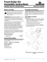
Disassembly of Existing Parts
Refer to Figure 1:
1. Remove pull ropes (#2) from transport locks (#1) and
discard.
AFM4211, AFM4214, & AFM4216 Only:
2. Disconnect hydraulic hoses (#3) from straight
adapter fittings (#4). Keep hoses for reattaching to
the hydraulic fittings later.
Disassembly of Existing Parts
Figure 1
Locate & Drill Mounting Holes
Older models will not have mounting holes and will need
to be drilled. The mounting holes are located differently
depending on which model the kit is attached to.
Model AFM4211
Locate and drill four 13/32" diameter holes in the toolbar
lock-up plate as shown in Figure 2.
Models AFM4214 & AFM4216
Locate and drill four 13/32" diameter holes in the toolbar
lock-up plate as shown in Figure 3.
Model AFM4522
Locate and drill four 13/32" diameter holes in the toolbar
lock-up plate as shown in Figure 4.
NOTE: Do not disconnect hydraulic hoses (#3) from
straight adapter fittings (#4) when installing this kit
on Model AFM4522 mower.
35488
Hole Pattern for AFM4211
Figure 2
Hole Pattern for AFM4214 & AFM4216
Figure 3
Hole Pattern for AFM4522
Figure 4
35482
35482
35482

Assembly Instructions
2/1/19 AFM Hydraulic Wing Unlock Assembly Instructions Manual No. 315-731M
3
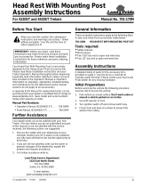
Hydraulic Mount Assembly
Figure 5
Hydraulic Mount Assembly
Refer to Figure 5:
1. Attach wire guide (#3) to hydraulic mount (#2) with
3/8"-16 x 1 1/4" GR5 carriage bolts (#5) and hex
flange nuts (#6). Tighten hex flange nuts to the
correct torque.
2. Attach hydraulic linkage (#4) to hydraulic mount (#2)
with 1/2" x 1 1/2" usable length clevis pin (#11) and
two 1/2" SAE flat washers (#7A & #7B) as shown.
3. Secure clevis pin with 1/8" x 1" cotter pin (#13). Bend
both legs of cotter pin around clevis pin (#11) to keep
cotter pin from falling out.
4. Attach base end of transport locking cylinder (#14) to
hydraulic mount (#2) with clevis pin (#1) and two 5/8"
SAE flat washer (#8A & #8B) as shown.
5. Secure clevis pin with two 1/8" x 1 1/4" cotter
pins (#10). Bend both legs of each cotter pin around
clevis pin to keep cotter pins from falling out.
6. Attach rod end of transport locking cylinder (#14) to
hydraulic linkage (#4) with 5/8" x 2 3/16" usable
length clevis pin (#12), two 3/4" USS flat washers,
and one 5/8" SAE flat washer (#8C) as shown.
7. Secure clevis pin with 1/8" x 1" cotter pin (#13). Bend
both legs of cotter pin around clevis pin to keep cotter
pin from falling out.
35480
Attach Hydraulic Mount Assembly
Models AFM4214 & AFM4216 Shown
Figure 6
Attach Hydraulic Mount Assembly
Refer to Figure 6:
1. Attach hydraulic mount assembly (#2) to toolbar lock-
up plate (#1) with 3/8"-16 x 1 3/4" GR5
bolts (#3), 3/8" flat washers (#5), 3/8" lock
washers (#6), and hex nuts (#4).
2. Tighten hex nuts (#4) to the correct torque.
WARNING
!
To prevent serious injury or death, stay clear of moving parts
and keep others away from moving parts.
3. See warning above. Do not attach warning decal (#7)
until step 4 below. Locate decal (#7) on toolbar
lock-up plate as follows:
• Models AFM4211, AFM4214, & AFM4216:
Centered decal between mounting holes in the
location shown on.
• Model AFM4522:
Locate decal just to the left or right of the mounting
holes.
4. Attach decal to toolbar lock-up plate as follows:
a. Clean area where decal is to be placed.
b. Spray soapy water on the surface where decal is
to be placed.
c. Peel backing from decal and press decal firmly
onto the surface.
d. Squeeze out all air bubbles with edge of a credit
card or with a similar type straight edge.
35485
Direction
Of
Travel

Assembly Instructions
AFM Hydraulic Wing Unlock Assembly Instructions Manual No. 315-731M 2/1/19
4
Assembly of Hydraulic Hoses
Refer to Figure 8 on page 5:
Model AFM4211:
1. Replace lower center adapter (#22) in port (E) with
new orifice adapter in the parts bag. Tighten orifice
adapter to port (E). Tighten existing hydraulic hose to
orifice adapter.
Models AFM4211, AFM4214, & AFM4216:
2. Unscrew hydraulic hoses (#16) from adapters (#15)
and attach tee fittings (#6A & #6B) to adapters (#15)
as shown and tighten.
3. Reattach hydraulic hoses (#16) to tee fittings (#11) as
shown and tighten.
4. Attach 28" long hydraulic hose (#12) to tee
fitting (#6A) and tighten.
5. Attach 32" long hydraulic hose (#13) to tee
fitting (#6B) and tighten.
6. Thread hydraulic hoses (#12 & #13) thru hole (C) on
Models AFM4214 and AFM4216 and hole (D) on
Model AFM4211.
Model AFM4522:
7. Attach quick release couplers (#21) to hydraulic
hoses (#19 & #20) and tighten.
8. Thread opposite end of hydraulic hoses (#19 & #20)
through hole (E) and then hole (C).
All Models:
9. Attach nut end of 90
o
elbows (#14) to hydraulic
cylinder ports (A & B) in transport locking cylinder.
Do not tighten at this time.
10. Attach short hydraulic hose (#12 or #19) to
elbow (#14) in port (B) and tighten hose to elbow.
11. Attach long hydraulic hose (#13 or #20) to
elbow (#14) in port (A) and tighten hose to elbow.
12. Tighten elbows (#14) to transport locking cylinder
ports (A & B).
Air Craft Cable & Spring Assembly
Refer to Figure 7:
There are two short aircraft cables (#1) and one long
aircraft cable (#1). The shorter cables attach to the wing
transport locks and the longer cable attaches to the
center deck transport lock.
1. Insert 3/8"16 x 1 1/2" GR5 bolt (#2) through SAE flat
washer (#4), 1/2" USS flat washers (#5A & #5B),
spring loop (#6), 1/2" USS flat washer (#5C), and
3/8" SAE flat washer (#4).
2. Start nylock nut (#3) on end of bolt (#2). Do not
tighten nylock nut at this time.
3. Loop free end of 3/16" aircraft cable (#1) around
bolt (#2) and between flat washers (#5A & #5B).
4. Secure free end with cable clamps (#7A & #7B). Do
not tighten cable clamps at this time.
5. Adjust end of cable to be approximately 3 3/8" back
from inside of loop as shown in Figure 7.
6. Use cable clamp (#7A) closest to the spring to create
a loop about 1 1/4" in diameter. The loop should be
big enough to allow rotation around the spring but
small enough not to come off washers (#5A & #5B).
7. Tighten cable clamp (#7A) closest to the spring.
8. Secure excess cable with remaining clamp (#7B) and
then tighten clamp (#7B).
9. Draw nylock nut (#3) up until all washers are snug.
Spring (#6) should swivel easily around bolt (#2).
10. Repeat steps 1 thru 9 for the other two assemblies.
Aircraft Cable & Spring Assembly
Figure 7
Attach Aircraft Cable Assemblies
Refer to Figure 8 on page 5:
1. Attach the long rear cable assembly (#4) to center
transport lock chain loop (#1) with 3/8"-16 x 1 1/2"
GR5 bolt (#7), two 3/8" SAE flat washer (#9), three
1/2" USS flat washers (#10), and nylock nut (#8) in
the order shown in Figure 8.
2. Draw nylock nut (#8) up until all washers are snug.
The spring should swivel easily around bolt (#7).
3. Attach the short right wing cable (#3A) to the right
transport lock chain loop (#1) with
3/8"-16 x 1 1/2" GR5 bolt (#7), two 3/8" SAE flat
washer (#9), three 1/2" USS flat washers (#10), and
nylock nut (#8) in the order shown in Figure 8.
4. Draw nylock nut (#8) up until all washers are snug.
The spring should swivel easily around bolt (#7).
5. Repeat steps 3 & 4 for the left wing cable (#3B).
6. Thread cable assemblies (#3A, #3B, & #4) through
wire guide (#5) as shown with cable assembly (#3B).
7. Attach loop end of cable assemblies (#3A, #3B, & #4)
to utility clevis (#17). Make sure cable (#4) is located
between cables (#3A & #3B).
8. Attach clevis (#17) to hydraulic linkage (#11) with
clevis pin (#18). Tighten clevis pin.
35481

Assembly Instructions
2/1/19 AFM Hydraulic Wing Unlock Assembly Instructions Manual No. 315-731M
5
Hydraulic Hoses & Aircraft Cable Assemblies (Model AFM4214 Shown)
Figure 8
35471
Direction
Of Travel
NOTE: ITEMS (#6A, #6B, #12, & #13) ARE USED
WITH AFM4211, AFM4214, & AFM4216 ONLY
NOTE: ITEMS (#19, #20, & #21)
ARE USED WITH AFM4522 ONLY
NOTE: ITEM (#22) IS
USED WITH AFM4211 ONLY

Assembly Instructions
AFM Hydraulic Wing Unlock Assembly Instructions Manual No. 315-731M 2/1/19
6
Adjust Hydraulic Transport Locks
Refer to Figure 9:
With transport locking cylinder (#6) fully retracted,
transport locks (#1) should be fully seated in tool bar
locking lugs (#2) with slight slack in aircraft cables (#5). If
needed, shorten or lengthen cables (#5) as follows:
1. Fully retract deck lifting cylinders (#7) and transport
lock cylinder (#6).
2. Check slack in all three aircraft cables (#5):
a. They should have slight slack and not be tight.
b. They should not be too slack or cables (#5) will not
be able to pull transport locks (#1) out of tool bar
locking lugs (#2).
3. If needed, adjust aircraft cables (#5) as follows:
a. Loosen cable clamps (#4A & #4B) and pull or let
out aircraft cable (#5) to create slight slack in
cable.
b. Use cable clamp (#4A) closest to the spring to
create a loop about 1 1/4" in diameter. The loop
should be big enough to allow rotation around the
spring but small enough not to come off the
washers.
c. Tighten cable clamp (#4A).
d. Secure excess cable with remaining clamp (#4B)
and then tighten clamp (#4B).
Folding Mower Decks
Refer to Figure 9:
1. Using tractor’s hydraulic control lever, raise all three
mower decks to transport position by retracting all
three hydraulic cylinders (#7) completely.
2. As the mower decks are raising, the three transport
locks (#1) will automatically lock in place. Make sure
they have locked in place before transporting.
3. If equipped, lock decks in place with deck float pins
(AFM4216 only) or deck lock bars (AFM4522 only).
NOTE: Figure 9 is shown with mower decks down
for clarity. Mower decks will need to be folded up
and locked in the transport locks to check for
adjustment of aircraft cable assemblies (#5).
Operating Hydraulic Transport Locks
Figure 9
Unfolding Mower Decks
Refer to Figure 9:
1. Using the tractor’s hydraulic control lever, fully retract
all hydraulic cylinders (#7) to remove weight from
transport locks (#1).
2. After hydraulic cylinders (#7) have fully retracted,
extend hydraulic cylinders (#7). The transport lock
hydraulic cylinder (#6) will extend first and will open
all three transport locks (#1) before hydraulic
cylinders (#7) start to extend.
3. Continue extending hydraulic cylinders (#7) to their
maximum stroke to utilize maximum flexibility of the
decks as they float over the terrain.
35473
IMPORTANT: Make sure deck floating pins are
removed and stored before unfolding the AFM4216
mower or deck lock bars are unlatched and stored
before unfolding the AFM4522 mower.
IMPORTANT: When unfolding mower, fully extend
cylinders to utilize maximum flexibility. Damage to
mower may occur if cylinders are not fully extended.

Assembly Instructions
2/1/19 AFM Hydraulic Wing Unlock Assembly Instructions Manual No. 315-731M
7
This page left blank intentionally

AFM Hydraulic Wing Unlock Assembly Instructions Manual No. 315-731M 2/1/19
8
1 315-729L HYDRAULIC WING UNLOCK MOUNTING ASSEMBLY 1
MOUNTING ASSEMBLY CONSIST OF THE FOLLOWING:
315-723H HYD WING UNLOCK MOUNT . . . . . . . . . . . . . . . . . . . . . . . . . . . . . . . . . . . . . . . .1
315-728H WIRE GUIDE . . . . . . . . . . . . . . . . . . . . . . . . . . . . . . . . . . . . . . . . . . . . . . . . . . . . .1
332-009D WING UNLOCK LINKAGE . . . . . . . . . . . . . . . . . . . . . . . . . . . . . . . . . . . . . . . . . . .1
802-023C HHCS 3/8-16X1 3/4 GR5 . . . . . . . . . . . . . . . . . . . . . . . . . . . . . . . . . . . . . . . . . . . .4
802-155C RHSNB 3/8-16X1 1/4 GR5 . . . . . . . . . . . . . . . . . . . . . . . . . . . . . . . . . . . . . . . . . . .2
803-014C NUT HEX 3/8-16 PLT . . . . . . . . . . . . . . . . . . . . . . . . . . . . . . . . . . . . . . . . . . . . . . .4
803-068C NUT HEX FLANGE 3/8-16 PLT. . . . . . . . . . . . . . . . . . . . . . . . . . . . . . . . . . . . . . . .2
804-012C WASHER FLAT 3/8 SAE PLT . . . . . . . . . . . . . . . . . . . . . . . . . . . . . . . . . . . . . . . . .4
804-013C WASHER LOCK SPRING 3/8 PLT . . . . . . . . . . . . . . . . . . . . . . . . . . . . . . . . . . . . .4
804-016C WASHER FLAT 1/2 SAE PLT . . . . . . . . . . . . . . . . . . . . . . . . . . . . . . . . . . . . . . . . .2
804-021C WASHER FLAT 5/8 SAE PLT . . . . . . . . . . . . . . . . . . . . . . . . . . . . . . . . . . . . . . . . .4
804-024C WASHER FLAT 3/4 USS PLT . . . . . . . . . . . . . . . . . . . . . . . . . . . . . . . . . . . . . . . . .2
805-127C PIN CLVS .50X1.52 USBL. . . . . . . . . . . . . . . . . . . . . . . . . . . . . . . . . . . . . . . . . . . .1
805-141C PIN CLVS .63X2.19 USBL . . . . . . . . . . . . . . . . . . . . . . . . . . . . . . . . . . . . . . . . . . .1
805-363C PIN COTTER 1/8 X 1 . . . . . . . . . . . . . . . . . . . . . . . . . . . . . . . . . . . . . . . . . . . . . . .2
810-555C CYL 1.5X2.5X.75 ROD W/CLEVIS . . . . . . . . . . . . . . . . . . . . . . . . . . . . . . . . . . . . .1
818-798C DECAL WARNING PINCH POINT GEN . . . . . . . . . . . . . . . . . . . . . . . . . . . . . . . . . . 1
2 315-730K HYDRAULIC WING UNLOCK BAG KIT 1
BAG KIT CONSIST OF THE FOLLOWING:
315-731M HYD WING UNLOCK MANUAL . . . . . . . . . . . . . . . . . . . . . . . . . . . . . . . . . . . . . . .1
315-724S WING UNLOCK WING CABLE ASSY (See breakdown of 315-724S below). . . . . .2
315-725S WING UNLOCK REAR CABLE ASSY (See breakdown of 315-725S below). . . . . .1
811-061C TE 9/16MJIC 9/16MJIC 9/16FJIC . . . . . . . . . . . . . . . . . . . . . . . . . . . . . . . . . . . . . .2
811-065C EL 9/16MJIC 9/16MORB . . . . . . . . . . . . . . . . . . . . . . . . . . . . . . . . . . . . . . . . . . . .2
811-442C HH1/4R2 028 9/16FJIC . . . . . . . . . . . . . . . . . . . . . . . . . . . . . . . . . . . . . . . . . . . . . .1
817-753C 10X16 PLASTIC MANUAL BAG . . . . . . . . . . . . . . . . . . . . . . . . . . . . . . . . . . . . . . .1
841-345C HH1/4R2 032 9/16FJIC . . . . . . . . . . . . . . . . . . . . . . . . . . . . . . . . . . . . . . . . . . . . . .1
890-018C 5/16 x 1 1/4 UTILITY CLEVIS WITH CLEVIS PIN
EACH 315-724S CONSIST OF THE FOLLOWING:
315-726V AIRCRAFT CABLE WITH CRIMP. . . . . . . . . . . . . . . . . . . . . . . . . . . . . . . . . . . . . . . 1
802-022C HHCS 3/8-16X1 1/2 GR5 . . . . . . . . . . . . . . . . . . . . . . . . . . . . . . . . . . . . . . . . . . . .2
803-078C NUT LOCK 3/8-16 NYLON INSERT . . . . . . . . . . . . . . . . . . . . . . . . . . . . . . . . . . . .2
804-012C WASHER FLAT 3/8 SAE PLT . . . . . . . . . . . . . . . . . . . . . . . . . . . . . . . . . . . . . . . . .4
804-017C WASHER FLAT 1/2 USS PLT . . . . . . . . . . . . . . . . . . . . . . . . . . . . . . . . . . . . . . . . .6
807-236C SPRING EXT. 1.0ODX5.OLX.095MW . . . . . . . . . . . . . . . . . . . . . . . . . . . . . . . . . . .1
890-672C U-BOLT WIRE ROPE CLP 3/16 GAL. . . . . . . . . . . . . . . . . . . . . . . . . . . . . . . . . . . .2
315-725S CONSIST OF THE FOLLOWING:
315-727V AIRCRAFT CABLE W/ CRIMP, LONG . . . . . . . . . . . . . . . . . . . . . . . . . . . . . . . . . . . 1
802-022C HHCS 3/8-16X1 1/2 GR5 . . . . . . . . . . . . . . . . . . . . . . . . . . . . . . . . . . . . . . . . . . . .2
803-078C NUT LOCK 3/8-16 NYLON INSERT . . . . . . . . . . . . . . . . . . . . . . . . . . . . . . . . . . . .2
804-012C WASHER FLAT 3/8 SAE PLT . . . . . . . . . . . . . . . . . . . . . . . . . . . . . . . . . . . . . . . . .4
804-017C WASHER FLAT 1/2 USS PLT . . . . . . . . . . . . . . . . . . . . . . . . . . . . . . . . . . . . . . . . .6
807-236C SPRING EXT. 1.0ODX5.OLX.095MW . . . . . . . . . . . . . . . . . . . . . . . . . . . . . . . . . . .1
890-672C U-BOLT WIRE ROPE CLP 3/16 GAL. . . . . . . . . . . . . . . . . . . . . . . . . . . . . . . . . . . .2
3 AFM4211 ONLY
811-694C ORAD 1/32 9/16 MORB 9/16 MJIC. . . . . . . . . . . . . . . . . . . . . . . . . . . . . . . . . . . . .1
Item Part No. Part Description Qty
Parts Listing for AFM4211, AFM4214, & AFM4216
315-732A AFM4211 HYDRAULIC WING UNLOCK KIT . . . . . . . . . . Items #1, #2, & #3
315-722A AFM4214 & AFM4216 HYDRAULIC WING UNLOCK KIT . . . . Items #1 & #2

2/1/19 AFM Hydraulic Wing Unlock Assembly Instructions Manual No. 315-731M
9
1 315-729L HYDRAULIC WING UNLOCK MOUNTING ASSEMBLY 1
MOUNTING ASSEMBLY CONSIST OF THE FOLLOWING:
315-723H HYD WING UNLOCK MOUNT . . . . . . . . . . . . . . . . . . . . . . . . . . . . . . . . . . . . . . . .1
315-728H WIRE GUIDE . . . . . . . . . . . . . . . . . . . . . . . . . . . . . . . . . . . . . . . . . . . . . . . . . . . . .1
332-009D WING UNLOCK LINKAGE . . . . . . . . . . . . . . . . . . . . . . . . . . . . . . . . . . . . . . . . . . .1
802-023C HHCS 3/8-16X1 3/4 GR5 . . . . . . . . . . . . . . . . . . . . . . . . . . . . . . . . . . . . . . . . . . . .4
802-155C RHSNB 3/8-16X1 1/4 GR5 . . . . . . . . . . . . . . . . . . . . . . . . . . . . . . . . . . . . . . . . . . .2
803-014C NUT HEX 3/8-16 PLT . . . . . . . . . . . . . . . . . . . . . . . . . . . . . . . . . . . . . . . . . . . . . . .4
803-068C NUT HEX FLANGE 3/8-16 PLT . . . . . . . . . . . . . . . . . . . . . . . . . . . . . . . . . . . . . . .2
804-012C WASHER FLAT 3/8 SAE PLT . . . . . . . . . . . . . . . . . . . . . . . . . . . . . . . . . . . . . . . . .4
804-013C WASHER LOCK SPRING 3/8 PLT . . . . . . . . . . . . . . . . . . . . . . . . . . . . . . . . . . . . .4
804-016C WASHER FLAT 1/2 SAE PLT . . . . . . . . . . . . . . . . . . . . . . . . . . . . . . . . . . . . . . . . .2
804-021C WASHER FLAT 5/8 SAE PLT . . . . . . . . . . . . . . . . . . . . . . . . . . . . . . . . . . . . . . . . .4
804-024C WASHER FLAT 3/4 USS PLT . . . . . . . . . . . . . . . . . . . . . . . . . . . . . . . . . . . . . . . . .2
805-127C PIN CLVS .50X1.52 USBL . . . . . . . . . . . . . . . . . . . . . . . . . . . . . . . . . . . . . . . . . . .1
805-141C PIN CLVS .63X2.19 USBL . . . . . . . . . . . . . . . . . . . . . . . . . . . . . . . . . . . . . . . . . . .1
805-363C PIN COTTER 1/8 X 1 . . . . . . . . . . . . . . . . . . . . . . . . . . . . . . . . . . . . . . . . . . . . . . .2
810-555C CYL 1.5X2.5X.75 ROD W/CLEVIS . . . . . . . . . . . . . . . . . . . . . . . . . . . . . . . . . . . . . 1
818-798C DECAL WARNING PINCH POINT GEN. . . . . . . . . . . . . . . . . . . . . . . . . . . . . . . . . . 1
2 315-735K HYDRAULIC WING UNLOCK BAG KIT 1
BAG KIT CONSIST OF THE FOLLOWING:
315-731M HYD WING UNLOCK MANUAL . . . . . . . . . . . . . . . . . . . . . . . . . . . . . . . . . . . . . . .1
315-724S WING UNLOCK WING CABLE ASSY (See breakdown of 315-724S below). . . . . .2
315-734S WING UNLOCK REAR CABLE ASSY XL (See breakdown of 315-734S below) . . . 1
811-065C EL 9/16MJIC 9/16MORB . . . . . . . . . . . . . . . . . . . . . . . . . . . . . . . . . . . . . . . . . . . .2
811-394C CP 3/4FORB MALE QD POPPET TYPE . . . . . . . . . . . . . . . . . . . . . . . . . . . . . . . .2
817-753C 10X16 PLASTIC MANUAL BAG . . . . . . . . . . . . . . . . . . . . . . . . . . . . . . . . . . . . . . .1
851-505C HH1/4R2 115 9/16FJIC 3/4 MORB . . . . . . . . . . . . . . . . . . . . . . . . . . . . . . . . . . . . .1
851-506C HH1/4R2 120 9/16FJIC 3/4 MORB . . . . . . . . . . . . . . . . . . . . . . . . . . . . . . . . . . . . .1
890-018C 5/16 x 1 1/4 UTILITY CLEVIS. . . . . . . . . . . . . . . . . . . . . . . . . . . . . . . . . . . . . . . . .1
EACH 315-724S CONSIST OF THE FOLLOWING:
315-726V AIRCRAFT CABLE WITH CRIMP . . . . . . . . . . . . . . . . . . . . . . . . . . . . . . . . . . . . . . 1
802-022C HHCS 3/8-16X1 1/2 GR5 . . . . . . . . . . . . . . . . . . . . . . . . . . . . . . . . . . . . . . . . . . . .2
803-078C NUT LOCK 3/8-16 NYLON INSERT . . . . . . . . . . . . . . . . . . . . . . . . . . . . . . . . . . . .2
804-012C WASHER FLAT 3/8 SAE PLT . . . . . . . . . . . . . . . . . . . . . . . . . . . . . . . . . . . . . . . . .4
804-017C WASHER FLAT 1/2 USS PLT . . . . . . . . . . . . . . . . . . . . . . . . . . . . . . . . . . . . . . . . .6
807-236C SPRING EXT. 1.0ODX5.OLX.095MW . . . . . . . . . . . . . . . . . . . . . . . . . . . . . . . . . . .1
890-672C U-BOLT WIRE ROPE CLP 3/16 GAL.. . . . . . . . . . . . . . . . . . . . . . . . . . . . . . . . . . .2
315-734S CONSIST OF THE FOLLOWING:
315-733V AIRCRAFT CABLE W/ CRIMP, XL . . . . . . . . . . . . . . . . . . . . . . . . . . . . . . . . . . . . .1
802-022C HHCS 3/8-16X1 1/2 GR5 . . . . . . . . . . . . . . . . . . . . . . . . . . . . . . . . . . . . . . . . . . . .2
803-078C NUT LOCK 3/8-16 NYLON INSERT . . . . . . . . . . . . . . . . . . . . . . . . . . . . . . . . . . . .2
804-012C WASHER FLAT 3/8 SAE PLT . . . . . . . . . . . . . . . . . . . . . . . . . . . . . . . . . . . . . . . . .4
804-017C WASHER FLAT 1/2 USS PLT . . . . . . . . . . . . . . . . . . . . . . . . . . . . . . . . . . . . . . . . .6
807-236C SPRING EXT. 1.0ODX5.OLX.095MW . . . . . . . . . . . . . . . . . . . . . . . . . . . . . . . . . . .1
890-672C U-BOLT WIRE ROPE CLP 3/16 GAL.. . . . . . . . . . . . . . . . . . . . . . . . . . . . . . . . . . .2
Parts Listing for AFM4522
315-736A AFM4522 HYDRAULIC WING UNLOCK KIT . . . . . . . . . . . . (Items #1 & #2)
Item Part No. Part Description Qty

Corporate Office: P.O. Box 5060
Salina, Kansas 67402-5060 USA
www.landpride.com
/