
INSTALLATION M ANUAL
ELECTRIC RANGE
Please read these instructions thoroughly before
installing and operating the range.
LRE30955S
LRE30755S
LRE30757S
LSE3094S
LSE3092S
LSRE307ST
LRE30855S
LRE30451S
LRE30453S
LRE3091S
LSES302ST
P/No.: MFL63724301
www.lg.com
ENGLISH ESPAÑOL

2
Part 1 SAFETY
1
BEFORE YOU BEGIN
Remove all tape and packing materials before using the range.
Dispose of all plastic bags after unpacking the range. Never allow children to play with packing materials.
IMPORTANT SAFETY INSTRUCTIONS
Read and follow all instructions before using your oven to prevent the risk of fire, electric shock, personal injury, or
damage when using the range. This guide does not cover all possible conditions that may occur. For further
assistance contact your service agent or manufacturer.
This is the safety alert symbol. This symbol alerts you to potential hazards that can cause personal injury to you and
others. All safety messages will follow the safety alert symbol with either the word “WARNING” or “CAUTION”.
This symbol will alert you to hazards or unsafe practices which could cause serious
bodily harm or death.
WARNING
This symbol will alert you to hazards or unsafe practices which could cause bodily
injury or property damage.
CAUTION
WARNING
• The information in this manual should be followed exactly.
- A fire or electrical shock may result causing property damage, personal injury or death.
• DO NOT step or sit on oven door. Install the Anti-Tip Bracket supplied with the range.
- The range could be tipped and injury might result from spilled hot liquid, food, or the range itself.
- If the range is pulled away from the wall for cleaning, service, or any other reason, ensure that the Anti-Tip Device is properly
reengaged when the range is pushed back against the wall.
• New branch-circuit installations (1996 NEC) for mobile homes, recreational vehicles, and
installations where local codes do not allow grounding through the neutral wire require a 4-
conductor UL listed range cord or 4 wire conduit connection.
• The middle (neutral or ground) wire of a 3 wire power cord or a 3 wire conduit has to be connected
to the middle post of the main terminal block. The remaining two wires of the power cord or
conduit have to be connected to the outside posts of the main terminal connection block.
- Failure to do so can result in electrical shock, severe personal injury or death.
• Only a 4-conductor power-supply cord kit rated 120/240 volts, 50 amperes and marked for use with
ranges with closed-loop connectors or open-end spade lugs with upturned ends shall be used.
The middle (neutral) wire of the power cord or 4-wire conduit has to be connected to the middle
post of the main terminal block. The other two wires of the power cord or conduit have to be
connected to the outside posts of the main terminal connection block. The 4th ground wire must
be connected to the frame of the range with the ground screw.
- Failure to do so can result in electrical shock, severe personal injury or death.
CAUTION
• Put on gloves during installation procedure.
- Failure to do so can result in bodily injury.
• Make sure that the wall covering, countertop and cabinets around the range can withstand
the heat (up to 194°F) generated by the range.
- Discoloration, delamination or melting may occur.
- This range has been designed to comply with the maximum allowable wood cabinet temperatures of 194°F.
• Cabinet storage space located above the surface units should be avoided.
• Install a range hood that projects horizontally a minimum of 5 inches beyond the bottom of
the cabinets If cabinet storage is to be provided.
- The risk of burns or fire by reaching over the heated surface elements can be reduced.

3
Part 1 SAFETY
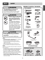
PARTS PROVIDED
NOTE
• Read all instructions contained in these installation
instructions before installing range.
• Remove all packing materials from the oven
compartments before connecting the electrical
supply to the range.
• Observe all governing codes and ordinances.
•
Be sure to leave these instructions with the consumer.
NOTE
Keep these instructions with your owner’s manual for
future reference.
• As when using any appliance generating heat, there
are certain safety precautions you should follow.
• Be sure your range is installed and grounded
properly by a qualified installer or service technician.
• Make sure the wall coverings around the range can
withstand the heat generated by the range.
• To eliminate the need to reach over the surface
elements, cabinet storage space above the elements
should be avoided.
TOOLS NEEDED
Gloves
Safety Glasses
Tape Measure
Pencil
Rear filler & 2 Screws
(LSE Series only)
PREPARE TO INSTALL THE RANGE
PARTS NOT PROVIDED
WARNING
• The information in this manual
should be followed exactly.
- A fire or electrical shock may result causing
property damage, personal injury or death.
CAUTION
• Put on gloves during installation
procedure.
- Failure to do so can result in bodily injury.
WARNING
• DO NOT step or sit on oven
door. Install the Anti-Tip
Bracket supplied with the
range.
- The range could be tipped and
injury might result from spilled hot
liquid, food, or the range itself.
- If the range is pulled away from the
wall for cleaning, service, or any
other reason, ensure that the Anti-
Tip Device is properly reengaged
when the range is pushed back
against the wall.
(For Anti-Tip Bracket Mounted
on Concrete Floors and Walls)
ENGLISH

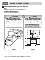
INSTALLATION DRAWINGS (LRE / LSRE Series only)
NOTE
SAVE FOR THE USE OF THE LOCAL ELECTRICAL INSPECTOR.
CLEARANCES AND DIMENSIONS (Figure 1)
To install range refer to the following Figure 1.
For installation in CANADA, a Free-standing range is not to be installed closer than
15
/32 (12mm) from any
adjacent surface.
MINIMUM DIMENSIONS (Figure 2)
* 30”(76.2 cm) minimum clearance between the top of the cooking surface and the bottom of an
unprotected wood or metal cabinet; or 24”(60.9 cm) minimum when bottom of wood or metal cabinet is
protected by not less than
1
/4”(6.4 cm) flame retardant millboard covered with not less than no. 28 MSG
sheet steel, 0.015”(0.381 mm) stainless steel, 0.024”(0.610 mm) aluminum or 0.020”(0.508 mm) copper.
** 15”(38.1 cm) minimum between countertop and adjacent cabinet bottom.
2 ERUGIF1 ERUGIF
A = 30”(76.2 cm) For U.S.A
= 30”(76.2 cm) ~ 31”(78.7 cm) For CANADA
CAUTION
• Make sure that the wall covering,
countertop and cabinets around the
range can withstand the heat (up to
194°F) generated by the range.
- Discoloration, delamination or melting may occur.
- This range has been designed to comply with the
maximum allowable wood cabinet temperatures
of 194°F.
CAUTION
• Cabinet storage space located above
the surface units should be avoided.
• Install a range hood that projects
horizontally a minimum of 5 inches
beyond the bottom of the cabinets If
cabinet storage is to be provided.
- The risk of burns or fire by reaching over the
heated surface elements can be reduced.
4
2
Part 2 PREPARE TO INSTALL THE RANGE

5
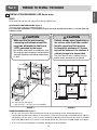
INSTALLATION DRAWINGS (LSE Series only)
NOTE
SAVE FOR THE USE OF THE LOCAL ELECTRICAL INSPECTOR.
CLEARANCES AND DIMENSIONS (Figure 1)
To install range refer to the following Figure 1.
For installation in CANADA, a Free-standing range is not to be installed closer than
15
/32 (12mm) from any
adjacent surface.
MINIMUM DIMENSIONS (Figure 2)
* 30”(76.2 cm) minimum clearance between the top of the cooking surface and the bottom of an
unprotected wood or metal cabinet; or 24”(60.9 cm) minimum when bottom of wood or metal cabinet is
protected by not less than
1
/4”(6.4 cm) flame retardant millboard covered with not less than no. 28 MSG
sheet steel, 0.015”(0.381 mm) stainless steel, 0.024”(0.610 mm) aluminum or 0.020”(0.508 mm) copper.
** 15”(38.1 cm) minimum between countertop and adjacent cabinet bottom.
24”
(60.9cm)
2 ERUGIF1 ERUGIF
A = 30”(76.2 cm) For U.S.A
= 30”(76.2 cm) ~ 31”(78.7 cm) For CANADA
CAUTION
• Make sure that the wall covering,
countertop and cabinets around the
range can withstand the heat (up to
194°F) generated by the range.
- Discoloration, delamination or melting may occur.
- This range has been designed to comply with the
maximum allowable wood cabinet temperatures
of 194°F.
CAUTION
• Cabinet storage space located above
the surface units should be avoided.
• Install a range hood that projects
horizontally a minimum of 5 inches
beyond the bottom of the cabinets If
cabinet storage is to be provided.
- The risk of burns or fire by reaching over the
heated surface elements can be reduced.
2
Part 2 PREPARE TO INSTALL THE RANGE
ENGLISH

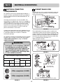
The Cord/Conduit connection plate is used for the
installation of power cord or conduit. For power cord,
install it with the connection plate as INSTALLED. For
conduit, remove the connection plate located below
the rear of the drawer body and use the conduit hole
(1
1
/
8
”) instead of power cord hole (1
3
/
8
”).
(Refer to Figure 5 and 6.)
3, 4 - Wire electrical wall Receptacle
6
3
CONNECT RANGE CORD
The Rear Access cover must be removed. Loosen the
three screws with a screwdriver. The terminal block
will then be accessible.
4
Drawer body cover
(LSE series only)
FIGURE 3
FIGURE 4
Range rating, watts
Specified rating
of power-supply-
cord kit, amperes
120/240 volts
3-wire
8,750 - 16,500
16,501 - 22,500
120/208 volts
3-wire
7,801 - 12,500
12,501 - 18,500
40 or 50A
50
Diameter (inches) of Range
connection Opening
Conduit
1
1
/
8
”
1
1
/
8
”
Power cord
1
3
/
8
”
1
3
/
8
”
Specified power-supply-cord kit rating
Part 3 ELECTRICAL CONNECTIONS
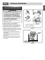
ELECTRICAL CONNECTION
REQUIREMENTS
This appliance must be installed and grounded on a
branch circuit by a qualified technician in accordance
with the National Electrical code ANSI/NFPA NO. 70 -
latest edition.
All wiring should conform to Local and NEC. This
range requires a single-phase, 3 wire, A.C 120/208V or
120/240V 60Hz electrical system. Use only a 3-conductor
or a 4-conductor UL-listed range cord with closed-
loop terminals, open-end spade lugs with upturned
ends or similar terminations. DO NOT install the
power cord without a strain relief.
A range cord rated at 40 amps with 120/240 minimum
volt range is required. If a 50 amp range cord is used,
it should be marked for use with 1
3
⁄8
” diameter
connection openings.
This appliance may be connected by means of conduit
or power cord. If conduit is being used, go to page 7
3 wire conduit connections or page 8 for 4 wire
conduit connections.
4 Wire receptacle (14-50R)
3 Wire receptacle (10-50R)
WARNING
• New branch-circuit installations (1996 NEC)
for mobile homes, recreational vehicles,
and installations where local codes do not
allow grounding through the neutral wire
require a 4-conductor UL listed range cord
or 4 wire conduit connection.
FIGURE 5
FIGURE 6
Remove the Conduit connection plate
Assemble the
strain relief hole
Reinstall the Cord/Conduit connection plate

7
Part 3 ELECTRICAL CONNECTIONS
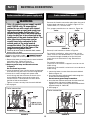
FIGURE 7
FIGURE 8
3-wire connection
Assemble the strain relief
to the 1
3
/
8
” opening in
Conduit connection plate
Separate Strain Relief
before installation
3-wire connection with a power supply cord
WARNING
• The middle (neutral or ground) wire of a 3
wire power cord or a 3 wire conduit has to
be connected to the middle post of the
main terminal block. The remaining two
wires of the power cord or conduit have to
be connected to the outside posts of the
main terminal connection block.
- Failure to do so can result in electrical shock, severe
personal injury or death.
Install the power cord as follows:
For power cord installations, Hook the strain relief
over the power cord hole (1
3
/
8
”) located below the rear
of drawer body. Insert the power cord through the
strain relief and tighten it. (Refer to Figure 7.)
DO NOT install the power cord without a strain relief.
1. Remove the lower 3 screws from the terminal block
and retain them. (Refer to Figure 8.)
2. Insert the 3 screws through each power cord
terminal ring and into the lower terminals of the
terminal block.
Make sure that the center wire (white/neutral) is
connected to the center lower position of the
terminal block.
3. Tighten 3 screws securely into the terminal block.
Do not remove the ground strap connections.
4. Go to page 9.
ENGLISH

8
Part 3 ELECTRICAL CONNECTIONS
Follow the instructions under “
CONNECT RANGE
CORD
” on page 5 to correctly install the strain relief.
1. Remove the lower 3 screws from the terminal block
and retain them. (Refer to Figure 9.)
Remove the ground screw and retain it.
2. Remove ground strap and discard as shown
in Figure 9.
Do not discard any screws.
3. Insert the ground screw into the power cord ground
wire terminal ring and secure it to the range frame.
4. Insert the 3 screws through each power cord
terminal ring and into the lower terminals of the
terminal block. Make sure that the center wire
(white/neutral) is connected to the center lower
position of the terminal block.
Tighten 3 screws securely into the terminal block.
5. Go to page 9.
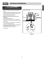
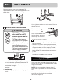
Install the conduit as follows:
Remove the Conduit connection plate from the rear of
drawer body and rotate it as shown in Figure 5. The
conduit hole (1
1
/
8
”) must be used.
First, prepare conduit wires as shown in Figure 10.
Second, install conduit as shown in Figure 6.
For conduit installations, after purchasing a strain
relief, insert it in the conduit hole (1
1
/
8
”). Then install
the conduit through the body of strain relief and
fasten the strain relief with its ring. Reinstall the
bracket.
For conduit connections :
If the wire in the conduit is copper it must be 8 or 10
AWG wiring.
If the wire in the conduit is aluminum it must be 6 or 8
AWG wiring.
1. Loosen the lower 3 screws from the terminal block.
(Refer to Figure 11.)
2. Insert the bare wire (white/neutral) end through the
center terminal block opening.
Do not remove ground strap connections.
3. Insert the two side bare wire ends into the lower left
and the lower right terminal block opening.
Tighten the 3 screws securely into the terminal block.
(approximately 35 - 50 IN-LB)
4. Go to page 9.
FIGURE 10
3-wire connection: conduit
or
3 wire 4 wire
FIGURE 9
4-wire connection
4-wire connection with a power supply cord
WARNING
• Only a 4-conductor power-supply cord kit
rated 120/240 volts, 50 amperes and
marked for use with ranges with closed-
loop connectors or open-end spade lugs
with upturned ends shall be used. The
middle (neutral) wire of the power cord or
4-wire conduit has to be connected to the
middle post of the main terminal block. The
other two wires of the power cord or
conduit have to be connected to the
outside posts of the main terminal
connection block. The 4th ground wire
must be connected to the frame of the
range with the ground screw.
- Failure to do so can result in electrical shock, severe
personal injury or death.
4
FIGURE 11
3-wire connection

9
Part 3 ELECTRICAL CONNECTIONS
1. Follow the instructions under “Install the conduit as
follows” on page 7 to correctly install the strain
relief.
DO NOT install the conduit without a strain relief.
2. Loosen the 2 lower left and right screws from the
terminal block. (Refer to Figure 12.)
Remove the lower 2 center screws.
3. Remove ground strap and discard as shown
in Figure 12.
Do not discard any screws.
4. Attach the ground bare wire end to range frame
and secure it in place with the ground screw (Refer
to figure 12.)
5. Insert the bare wire (white/neutral) end through the
center terminal block opening.
6. Insert the two side bare wire ends into the left and
the right terminal block opening.
Tighten the 3 screws securely into the terminal
block. (approximately 35 - 50 IN-LB)
7. Go to page 9.
FIGURE 12
4-wire connection
4-wire connection: conduit
ENGLISH

Replace the access cover on the range back. To
replace the wire cover, insert double projections in the
pockets located below the opening and tighten the
three screws.
ANTI-TIP DEVICE INSTALLATION
1. Locate the bracket using the template
An Anti-tip bracket is packaged with template. The
instructions include necessary information to
complete the installation.
Read and follow range installation instruction sheet
(template).
2. Level the range
Level the range by adjusting the leveling legs with a
wrench.
10
Use a spirit level to check your adjustments. Place the
level diagonally on the oven rack, and check each
direction for level.
First check direction 1
.
After check direction
2
.
If the spirit level doesn’t show
level on the rack, adjust the
leveling legs with a wrench.
FINAL INSTALLATION
• Move range close enough to the opening to plug
into the receptacle.
• Slide range into position insuring that the left back
leg slides under the anti-tip bracket. Range will sit 0”
away from the back wall when properly installed.
• Carefully tip range forward to insure that the anti-tip
bracket engages the range back brace and prevents
tip-over.
• Turn on electrical power. Check range for proper
operation as described in owner’s manual.
If the counter does not bridge the opening at the rear
wall the rear filler kit, that is provided with the slide in
range, will be needed.
NOTE : If the countertop depth is greater than 25”
there will be a gap between the filler kit and the back
wall.
If the countertop depth is less than 24”, the control
panel will not sit flush with the countertop.
(See figure 1 on page 5)
5
6
Part 4 INSTALL THE RANGE
WARNING
• DO NOT step or sit on oven
door. Install the Anti-Tip
Bracket supplied with the
range.
- The range could be tipped and
injury might result from spilled hot
liquid, food, or the range itself.
- If the range is pulled away from the
wall for cleaning, service, or any
other reason, ensure that the Anti-
Tip Device is properly reengaged
when the range is pushed back
against the wall.
Optional rear filler

Printed in Mexico
-
 1
1
-
 2
2
-
 3
3
-
 4
4
-
 5
5
-
 6
6
-
 7
7
-
 8
8
-
 9
9
-
 10
10
-
 11
11


Ask a question and I''ll find the answer in the document
Finding information in a document is now easier with AI
Related papers
-
LG LDE3017SW/00 Installation guide
-
LG LDE3019ST Installation guide
-
-
LG LRE3023ST User manual
-
-
LG LDE3017ST User manual
-
-
LG LRE30757ST/00 Installation guide
-
LG LDE3031ST Installation guide
-
Other documents
-
LG STUDIO LSSE3027ST Installation guide
-
LG SIGNATURE LUTE4619SN Installation guide
-
-
Maytag MEP5775BAF - 30in Electric Range Dimensions
-
-
LG Electronics LTE4815BD Installation guide
-
-
-
-
 Kenmore Elite 96043 Installation guide
