O.S. engine max-140rx Owner's manual
- Category
- Engine
- Type
- Owner's manual
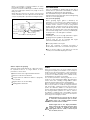
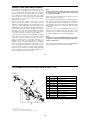
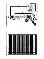
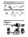
O.S. engine max-140rx is a single-cylinder, two-stroke engine designed for FAI aerobatic competition. It features a new O.S. Type 70A carburetor and O.S. Type PD-06 diaphragm fuel pump, providing stable power and consistent throttle response. The engine is equipped with a tuned silencer and exhaust header pipe to maximize performance. It is capable of producing high specific output and has a high power-to-weight ratio. The max-140rx is suitable for experienced modelers and is ideal for F3A competition.
O.S. engine max-140rx is a single-cylinder, two-stroke engine designed for FAI aerobatic competition. It features a new O.S. Type 70A carburetor and O.S. Type PD-06 diaphragm fuel pump, providing stable power and consistent throttle response. The engine is equipped with a tuned silencer and exhaust header pipe to maximize performance. It is capable of producing high specific output and has a high power-to-weight ratio. The max-140rx is suitable for experienced modelers and is ideal for F3A competition.


-
 1
1
-
 2
2
-
 3
3
-
 4
4
-
 5
5
-
 6
6
-
 7
7
-
 8
8
-
 9
9
-
 10
10
-
 11
11
-
 12
12
-
 13
13


O.S. engine max-140rx Owner's manual
- Category
- Engine
- Type
- Owner's manual
O.S. engine max-140rx is a single-cylinder, two-stroke engine designed for FAI aerobatic competition. It features a new O.S. Type 70A carburetor and O.S. Type PD-06 diaphragm fuel pump, providing stable power and consistent throttle response. The engine is equipped with a tuned silencer and exhaust header pipe to maximize performance. It is capable of producing high specific output and has a high power-to-weight ratio. The max-140rx is suitable for experienced modelers and is ideal for F3A competition.
Ask a question and I''ll find the answer in the document
Finding information in a document is now easier with AI
Related papers
-
O.S. Engines OSMG0898 Owner's manual
-
O.S. engine MAX-32SX Owner's Instruction Manual
-
OS Engines FT-160 User manual
-
-
-
-
-
-
-
Generac MAX-12CV HyperMAX-12CV-X Hyper User manual
Other documents
-
-
 Hobbico FL-70 Owner's manual
-
 Hobbico FL-70 Owner's manual
-
-
-
-
-
-
-

