Dometic Basic Chiller Control Operating instructions
- Category
- Thermostats
- Type
- Operating instructions

BasicChillerControl
OperationsManual
DometicGroupMarineDivision
Rev.20230414
L‐3527English
P/N338238
COPYRIGHT©2011‐2018DometicGroupMarineDivision.AllRightsReserved.
Nopartofthispublicationmaybereproduced,translated,storedinaretrievalsystem,ortransmittedinanyformorbyanymeanselectronic,
mechanical,photocopying,recordingorotherwisewithoutpriorwrittenconsentbyDometicMarine.Everyprecautionhasbeentakeninthe
preparationofthismanualtoinsureitsaccuracy.However,DometicMarineassumesnoresponsibilityforerrorsandomission.Neitherisany
liabilityassumedfordamagesresultingfromtheuseofthisproductandinformationcontainedherein.

Tableof
Con
t
en
t
s
INTRODUCTION...............................3
PGD1NAVIGATION............................3
TOUCHSCREENNAVIGATION...................2
MAINPAGE.................................2
CHILLERENABLE .........................2
CHILLERSUMMARY........................2
CHILLERSTAGE ..........................2
TRENDS ................................2
ALARMS ................................2
REMOTESUPPORT........................3
LOGO ..................................3
OFFICON ..............................3
COOLICON..............................3
HEATICON ..............................3
ELECTRICHEATICON:ONLYIFOPTION
IS
INSTALLED ..............................3
SETPOINTTHERMOMETERS ..................3
GENERALINFORMATION......................4
DIGITALINPUTS.............................4
SAFETYINPUTS ..............................4
FS–CHILLWATERFLOWSWITCH ................4
REFRIGERANTHI–HIGHSIDEPRESSURELIMIT ......4
REFRIGERANTLOW–LOWSIDEPRESSURELIMIT ....5
ANALOGINPUTS..............................5
HIGHLIMITTEMPERATURE ......................5
FREEZETEMPERATURE ........................5
PRESSURETRANSDUCERS ....................5
SUCTION…………………………………….........5
DISCHARGE……………………….…………….......5
RELAYOUTPUTS ............................6
COMP–COMPRESSOR .......................6
CWP–CHILLWATERPUMP ...................6
SWP–SEAWATERPUMP.....................6
RV–REVERSINGVALVE......................6
EH–ELECTRICHEAT ........................6
FAULT ....................................6
SYSTEMOVERVIEW...........................6
SYSTEMPOWER‐UP..........................6
SOFTWAREREVISION......................6
STARTUP..................................6
OPERATIONALCHECKS ........................6
SETPOINTS.................................6
COOLING...............................6
HEATING ...............................7
COMPRESSORSTAGINGTIME..............7
RUNMODE–COOLING........................7
RUNMODE–REVERSECYCLEHEATING...........7
RUNMODE–ELECTRICHEATING................7
OPERATIONALMODES ........................7
PUMPOPERATION...........................7
CHILLEDWATERPUMP ....................7
SEAWATERPUMP .......................7
COOLINGMODE .............................8
HEATINGMODE .............................8
STATUSSCREENNAVIGATION..................8
APPENDIXI:NAVIGATIONTREE..................14
APPENDIXII:INSTALLATION&SETUP
PROCEDURES.................................24
InitialWiring...............................24
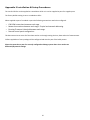
BasicWiringDiagram........................25
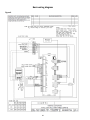
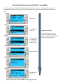
FirmwareCompatibility.......................26
Networking................................27
SettingTimeandDate.......................30
ElectricHeat...............................31
SelectTemperatureType.....................32
APPENDIXIII:ALARMTABLE....................33
APPENDIXIV:DEFAULTPARAMETERS............34

3
INTRODUC
T
I
ON
TheDometicPLCcontrolsisamicrocontroller‐basedunitdesignedtocontrolmultiplechillers.Thisdesignallowstheuserflexibility
intheapplicationandimprovedcontrolsandprotection.ThePLCChillerusestemperaturedifferentialandhysteresistomanage
thecapacityofthechillerinsingleormultistageapplication.
Thisapplicationsupportsthefollowing:
o Selectionandsequencingofuptosixchillers
o Selectionandsequencingofonechillwaterpumpandoneseawaterpump
o Selectionandsequencingofupto6EHheaters
o Sequencingofdevicesforruntimeequalization
o Alarmsandinterlocks
o Troubleshootinghelp
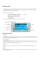
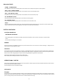
ThemaininterfacesupportedwillbetheLCDdisplay,referredtoasthePGD1display.
Figure
1:
PGD1Button
De
sc
r
i
ptio
n
PGD1
NA
V
IGA
T
I
ON
EnterButton
ThePGD1controllerscreenwillautomaticallybootuptotheMainscreen.Thisscreenallowsyoutoenableordisablethechillerby
pressingtheEnterbutton.PressingtheEnterbuttonwilltakeyoutotheareaofscreenyouwishtomodify.Pressentermultipletimesif
requiredtoscrolldowntotheareayouwishtoselect.
ScrollUp/DownButtons
Thisbuttonwillbeusedtomodifythevaluesuchastemperaturesetpointorprobeadjustmentvalues.TheScrollUporScrollDown
buttonwillalsonavigateyoufrompagetopageofthecontroller.Theflashingcursormustbeintheupperleft‐handcornerforthepage
navigation.Pressingenterrepeatedlywillmoveittothatlocation.
EscButton
TheEscbuttonisusedtoexityourpresentscreenandtakeyoubackonescreen.Pressingitmultipletimeswilltakeyoubacktothe
Mainscreen.
PrgButton
Thisbuttontakesyoutothesystemmenus.Onceatthemenus,usethescrollbuttonstoscrollthroughthevariousoptions.Pressing
enterwillselectthatmenuitem.
ScrollDown
ScrollUp
Enter
AlarmIndicator
ProgramMode
EscapetoExit

4
AlarmButton
Thisbuttonwillflashredifthereisanactivealarm.Pressingthisbuttonwilltakeyoutotheactivealarmscreentodisplaythealarm.
Onceinthealarmscreen,usetheup/downbuttonstoscrollthroughalarms.TheAlarmscreencapturesasnapshotofthesystem
parametersatthetimeofthefault.PressandholdtheAlarmbuttonfor3secondstocleartheactivealarmifthefaulthasbeen
corrected.
GE
NE
RALINFORMATION
TheDometicPLCcontrolsisamicrocontroller‐basedunitdesignedtocontrolmultiplechillers.Thisdesignallowstheuserflexibility
intheapplicationandimprovedcontrolsandprotection.ThePLCChillerusestemperaturedifferentialandhysteresistomanage
thecapacityofthechillerinsingleormultistageapplication.
Thechillersystemwillcomeprogrammedfromthefactorywiththeoptionsenabledforthatsystem.Althoughthesystemoffers
flexibility,theseoptionscanonlybeenabledbyafactoryrepresentative.
TheuserwillbeabletoselectbetweenCool,HeatorElectricHeatmodeoperationinsinglestageconfigurationorInamultistage
configuration.
ThePLCcontrollerisinternallygroundedwithisolationbetweeninputsandoutputs.Additionally,theoutputrelaysofferdouble
isolationsothatdifferentvoltagescanbeusedforgroupsofrelays.
Thesystemwillutilizevarioussensortypesformeasuringanalogtemperaturesandpressures.Fortemperaturemeasurements,the
systemwilluseNTCtype10K@77°thermistors.Pressuretransducersareratiometric0‐650PSI(45bar)rangeforbothsuctionand
dischargemonitoring.
AvailableOptions:
1. CompressorCurrentMonitoring
2. PumpCurrentMonitoring(SWandCW)
3. CondenserFreezeProtection
4. ElectricHeat
5. EEVControl
6. PressureTransducers
7. LoadSheddingInputSignal
8. LowCurrentAlarmtoindicateifsystemisnotactuallyrunningwhenenabled.(PumpsandCompressor)
9. ReturnorSupplyWaterControl
DIGITAL
IN
PUTS
Digitalinputsareusedtomonitorthestatusoftheprotectioncircuitsforthesystem.
SAFETYI
NP
U
T
S
Alldiscreteinputswillbecheckedbeforethesystemwillbeenabled.Anyfaultsdetectedonstart‐upmustbeverifiedandcleared
viathePLCbeforesystemwillstartnormaloperation.
FS–
CHILLEDWATERFLOW
SWIT
C
H
WiththesystemineitherheatingorcoolingmodetheFlowswitchmustbeclosedpriortosystemstartingorastagebeingenabled.
InoperationifFlowislostformorethan10consecutiveseconds,thecompressororheatrelaywillbedisabled.Aflowswitchfault
willberecordedanddisplayed.
ACWFlowfaultwillberecordedandsystemwillbeinlockoutandamanualrestartwillberequired.ThePLCwillnotallowthecompressor
orelectricheatrelaytobeenergizedforthestagethathaslostfloworthewholesystemifacommonflowswitchisbeingused.
FaultmustbemanuallyacknowledgedviathePLCandclearedpriortore‐enablingthesystemorstage.
REFRIGERANT
HI–
HIGHSIDEPRESSURE
L
IM
I
T
ThePLCwillimmediatelyacknowledgeanopencircuitiftheHIpressureswitchistrippedandde‐energizethecompressor.Itwillrecord
anddisplayhighpressurefaultonthealarmscreen.IfthePLCdetectsahighpressurefaultduringoperation,aHPfaultwillbedisplayed
andrecorded.ThePLCwillnotallowthecompressorrelaytobere‐energized,untilswitchisintheclosedposition.
ThefaultmustbemanuallyacknowledgedviathePLCandclearedpriortore‐enablingthesystemorstage.

5
REFRIGERANTLOW
–
LOWSIDEPRESSURE
L
IM
I
T(Optional)
ThePLCwillimmediatelyacknowledgeanopencircuitifthelowpressureswitchistrippedandde‐energizethecompressor.Itwill
recordanddisplaylowpressurefaultonthealarmscreen.IfthePLCdetectsalowpressurefaultduringoperation,aLPfaultwillbe
displayedandrecorded.ThePLCwillnotallowthecompressorrelaytobere‐energized,untilswitchisintheclosedposition.
ThefaultmustbemanuallyacknowledgedviathePLCandclearedpriortore‐enablingthesystemorstage.
ANALOGINPUTS
HIGHLIMIT
T
E
M
P
ERA
TU
RESETPOINT
ThehighlimittemperaturesensoriscontinuouslymonitoredwhetherinCooling,ReverseCycleorElectricHeatmode.
Thissensorisusedtodetectahightemperatureconditioninthesupplywaterfromthechiller.Ifthechilledwatertemperatureissensed
tobegreaterorequalto125°F(51.7°C),allenabledcompressorrelayswillbede‐energized,turningoffthecompressor(s)ifoperating
inreversecyclemode.Ifelectricheatisbeingused,allenabledheaterrelayswillbede‐energized,turningofftheheatingelement(s).
Asthetemperaturefalls,thecompressororelectricheatrelaywillre‐energizewhenthetemperaturereaches110°F(43.3°C).
Ahightemperaturefaultwillberecordedanddisplayedifthesystemexceedsthealarmsetpoint.Inahightemperaturesituation,PLC
willnotallowthecompressororelectricheatrelaytobeenergized.Thefaultmustbemanuallyacknowledgedontheactivealarm
screenandclearedpriortore‐enablingthesystemorstage.
Ifatemperaturesensorisbadornotconnected,thePLCwilldisplayanalarmforthatsensor.
FREEZE
T
EM
P
E
R
A
T
U
RESETPOINT
ThelowlimittemperaturesensoriscontinuouslymonitoredwhetherinCooling,ReverseCycleorElectricHeatmode.
Thissensorisusedtodetectafreezeconditioninthesupplywaterofthechiller.Ifthechilledwatertemperatureissensedtobeequalto
orlessthan38°F(3.3°C),thenthecompressorrelaywillbede‐energized,shuttingoffthecompressor.Asthetemperaturerises,the
compressorrelaywillre‐energizewhenthetemperaturereaches42°F(5.6°C).
Alowtemperaturefaultwillberecordedanddisplayedifthesystemfallsbelowthealarmsetpoint.Inalowtemperaturesituation,
PLCwillnotallowthecompressororelectricheatrelaytobeenergized.Thefaultmustbemanuallyacknowledgedontheactivealarm
screenandclearedpriortore‐enablingthesystemorstage.
Ifatemperaturesensorisbadornotconnected,thePLCwilldisplayanalarmforthatsensor.
CondenserFreezeProtection(Optional)
Thesystemisequippedwithatemperaturesensormountedtothecondensercoil.Thissensoristheretosensethecoiltemperature.In
heatmodeifthecoiltemperaturedropsbelow40°F,thePLCcontrolswillautomaticallylowerthespeedofthecompressortohalfthe
speedthatitwascurrentlyrunning.Thedisplaywillindicate“FreezeDefrost”whileperformingthisoperation.
PRESSURE
TR
AN
SD
UCERS
SUCTIONPressure
ThesuctionpressureiscontinuouslymonitoredbythePLC.Ifthesuctionpressureisbelowthealarmsetpointforlongerthanthe
programmedtimedelay,afaultwilloccur.Thislowsuctionfaultwillberecordedanddisplayedonthealarmscreen.
ThefaultmustbemanuallyacknowledgedviathePLCandclearedpriortore‐enablingthesystemorstage.
DISCHARGEPressure
ThedischargepressureiscontinuouslymonitoredbythePLC.Ifthedischargepressureisabovethealarmsetpointforlongerthanthe
programmedtime,afaultwilloccur.Thishighpressurefaultwillberecordedanddisplayedonthealarmscreen.
ThefaultmustbemanuallyacknowledgedviathePLCandclearedpriortore‐enablingthesystemorstage.

6
RELAYOUTPUTS
COMP
–
C
OMPR
E
SSOR
PLCCOMPoutputwillprovideswitchedpowertothecontactorcoiltoenablethecompressornormaloperation.
CWP
–
CHILLWATER
P
UM
P
PLCCWPoutputwillprovideswitchedpowertothecontactorcoilsforthechilledwaterpump.
SWP
–
SEAWATER
P
UM
P
PLCSWPoutputwillprovideswitchedpowertothecontactorcoilsfortheseawaterpump.
RV–
REVERSING
VAL
VE
PLCRVoutputwillprovideswitchedpowertothecoilsforthereversingvalve.
EH–
ELECTRIC
H
EA
T
PLCEHoutputwillprovideswitchedpowertothecontactorcoilsfortheelectricheat.
F
AULT
ProvidesaNormallyOpen(NO)contactpoint.AnyfaultconditionwillclosetheNOcontact.Thisoutputcanbeusedtopoweralight,
relay,orinterfacetoaship’smonitoringsystem.Theoutputonthisterminalwillbe230VAC.
SYSTEM
OVERVIE
W
SYSTEM
P
OWER
‐
UP
SOFTWAREREVI
S
I
O
N
Uponapplyingpowertothesystem,thedisplaywillindicatethesoftwarerevisionnumberordisplayitonthemainstatus
screen.
PLCisenabledandwaitingforuserselection.
MODBUS
ThePLCcomeswitha3wireModbusconnectionaspartoftheelectricalbox.Thisconnectionisusedformultistageconfigurationand
networkingtoaboatmanagementsystem.
S
TA
RT
UP
ThePLCChillercontrollercanbeoperatedasasingleoramultistagechillerplant.Duringinitialsetup,thesystemwillbeconfiguredfor
thenumberofstagesandtheavailableoptions.SelectbetweenReturnwaterorSupplywatercontrol.Theuserhastheoptiontoselect
betweenmetricvaluesbeingdisplayedorImperialvaluesbeingdisplayedduringoperationofthesystem.
ChilledwatersetpointwillbeenteredforCoolandHeatmode.
Onceenabled,CWandSWpumpswillbeturnedonforoperation.
OPERATIONAL
CHECK
S
OncethePLCisenabledthesystemwillconductpre‐startupchecks.ThePLCprogramwillcheckallCWflowswitchesforfaults.ThePLC
willalsocheckHPandLPswitchesforfaults.
Individualstagefaultswillonlydisablethatstage.
S
ET
POI
N
T
S
C
OO
LI
N
G
Coolingset‐pointisanadjustableparameterforReturncontrol(default)from48°F(8°C)to58°F(14°C)inonedegreeincrementsandfor
Supplycontrolfrom42°F(5°C)to58°F(14°C).Toadjustthecoolingsetpoint,simplytouchthePLCscreenandchangetodesirednewset
point.Incoolingmodeyouwillnotbeabletoenteranumberoutsideofthisrange.

7
H
EATING
Heatingset‐pointisanadjustableparameterfrom95°F(35°C)to120°F(49°C)inonedegreeincrements,forbothReturn&Supply
control.Toadjusttheheatingsetpoint,simplytouchthePLCscreenandchangetodesirednewsetpoint.Inheatingmodeyouwillnot
beabletoenteranumberoutsideofthisrange.
C
OMPRESSOR
S
TAGING
T
IM
E
CompressorstagingtimeisaPLCadjustableparameterfrom10secondsto110secondsin10‐secondincrements.Toadjustthestaging
time,simplytouchthePLCscreenandchangetodesirednewsetpoint.Userwillnotbeabletoenteranumberoutsideofthisrange.
OncethePLCinitiatesacoolingcycle,thestagingtimeisthetimeitwilltake(inseconds)forthenextcompressorrelaytoclose.
RUNMODE
–
C
OOL
ING
Compressorrotationisactiveduringrunmode.Thecompressorwiththelowestrunninghourswillbeenabledfirstandcompressorwith
thehighestrunninghourswillbedisabledfirst.
FirststagewillbeenabledandthecompressorwillstartafterCWandSWflowsarestablefor10seconds(default).
Firststagewillcontinuetorunfor1minutebeforeenablingthenextstage.Ifthelooprequiresdemand,thenthenextstagewillbe
enabled.
R
UN
M
ODE
–
R
EVERSE
C
YCLE
H
EA
TI
NG
Compressorrotationisactiveduringrunmode.Thecompressorwiththelowestrunninghourswillbeenabledfirstandcompressorwith
thehighestrunninghourswillbedisabledfirst.
EnableReverseCycleHeatonlyforthesystem.
FirststageheatingwillbeenabledandthecompressorwillstartafterCWandSWflowsarestablefor10seconds.
Firststagewillcontinuetorunfor5minutesbeforeenablingthenextheaterstage.Ifthelooprequiresdemand,thenthenextstagewill
beenabled.
R
UN
M
ODE
–
E
LECTRIC
H
EAT
I
N
G(optionalheaterbarrel)
Heaterrotationisactiveduringrunmode.Theheaterwiththelowestrunninghourswillbeenabledfirstandtheheaterwiththehighest
runninghourswillbedisabledfirst.
EnableElectricHeatonlyforthesystem.
FirststagewillbeenabledandtheelectricheaterwillstartafterCWflowisstablefor10seconds.
Firststagewillcontinuetorunfor5minutesbeforeenablingthenextheaterstage.IfthePIDlooprequiresdemandthenthenext
stagewillbeenabled.
OPERATIONAL
M
ODES
PUMP
O
PE
RA
TI
O
N
CHILLEDWATER
P
UM
P
Thechilledwaterpumprelayshallcloseifthesystemisinheatmodeorcoolmode.Thepumpwillbeenabled5secondpriortothe
firststagebeingenabled.Pumpwillbeonforcontinuousoperationwhensystemisenabled
SEAWATER
P
UM
P
Theseawaterpumpwillhaveaselectableoperatingmodebetweencontinuousoperationorcyclewithcompressoroperation.
Thedefaultconfigurationistocyclewiththedemand.
Theseawaterpumprelayshallclose5secondsbeforethecompressorstartsinheatingorcoolingmodesandwillopen5seconds
afterthelastcompressorcycleiscompleted.Ifimmersionheatingisavailableandused,theseawaterpumpwillbedisabled.
Inamultistageconfigurationthepumpoutputscanbedaisychainedatthebackoftheunittosupplypowertothepumps.
Thiswillallowanystagetosupplypowertothepumpswhenbeingstagedonandoffandasaredundantcontrolforthepumps.

8
COOLING
M
ODE
CoolingmodeisenteredwhenCoolisselectedonthetouchscreenorwiththedisplaybuttons.Thesystemwillautomaticallystartcooling
dependingontemperaturesetpoint.Thepumpswilloperateasdescribedinthepumpoperationsection.
Theboardwillenergizethecompressorrelayifreturnwater/supplywatertemperatureisabovethecoolingsetpointandthestaging
delayhaselapsed.
Thecompressorwillcontinuetorununtilthecoolingsetpointhasbeenreachedoranalarmconditionexists.Astagewillhavea
minimumruntimeof100secondsbeforeitcanbeturnedoffandaminimumofftimeof120secondsbeforeitcanbere‐enabled.This
minimumontimeisrequiredtoensurethatthesystemisnotcyclingonandoffandnotallowingthecompressortoproperlywarm‐up.
Thisensuresproperoillubricationofthesystem.Ifthesystemcallsforastagetobetoggledon/off,thenextavailablestagewillbeused
thatmeetsthestagingcriteria.Loadsheddingwilloccurinmultistageoperationwhenapproachingchilledwatersetpoint.Thereversing
valveistoggledtorelieveheadpressureattheendofacompressorruncycle.
HEATING
M
OD
E
ReverseCycleHeatingmodeisenteredwhenHeatisselectedonthetouchscreenorwiththedisplaybuttons.Thesystemwill
automaticallystartheatingdependingonthetemperaturesetpoint.Thepumpswilloperateasdescribedinthepumpoperationsection.
ThereversingvalverelaywillbeenergizedtochangetheunittooperateinReverseCycleHeatingmode.
ThePLCwillenergizethecompressorrelayifreturn/supplywatertemperaturebelowtheprogrammedheatingsetpointandthestaging
delayhaselapsed.Thecompressorwillcontinuetorunandthereversingvalvewillremainenergizeduntiltheheatingsetpointhas
beenreachedoranalarmconditionexists.
ElectricHeatingmodeisenteredwhenElectricHeatisselectedonthetouchscreenorwiththedisplaybuttons.Thesystemwill
automaticallystartheatingdependingonthetemperaturesetpoint.
ThePLCwillenergizetheheaterrelayifreturn/supplywatertemperatureisbelowtheprogrammedsetpointandthestagingdelay
haselapsedinamultistageconfiguration.
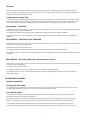
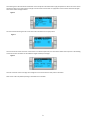
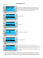
StatusScreenNavigation
Themainhomescreenisthestatusscreenwherethesinglestageoperationcanbereviewedorinamultistageconfigurationtheusercan
scrollandseethevaluesofthechilledwaterandotherparametersoftheadditionalstages.Theuserwillsimplyusethedownarrowkey
toscrollthroughthevariousparametersbeingdisplayedontheLCDscreen.TheLCDscreenwillalsoindicateonthemainscreenthe
modeofoperationwhetheritisCool,HeatorEHmode.Themainscreenwillalsoindicateifthereisanalarmpresentonthesystemby
flashingthewordalarminthelowerright‐handcornerorLoadsheddingifithasbeenactivated.
Figure2

9
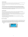
Thefollowingscreenwillindicatethechilledwaterreturntemperaturethechilledwatersupplytemperatureaswellasthecontrolsensor
temperaturewhichisthevaluebasedonthetypeofcontrolchosen.Returnwaterorsupplywatercontrolandthiswillbetheaveraged
valueofthenumberofstagesenabled.
Figure3
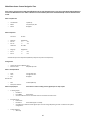
Thesecondscreenfollowingthemainscreenwillcontaininformationonthepumpstatus.
Figure4
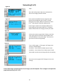
Thethirdscreenwillcontainthechiller1informationorthewatertemperatures,thestatusofthesafetiesandcompressor.Thefollowing
screenswillcontaininformationfortheadditionalstagesenabledupto6stages.
Figure5
Thefinalscreenwillcontaintheimageoftherefrigerantcircuitandcontainthevalvepositioninformation.
Note:Screenordersmaydifferdependingonwhatfeaturesareenabled.

10
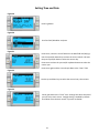
MainMenuItems:ScreenNavigationTree
Pressentertoselectitemstoviewandup/downarrowstoscrollthroughscreens.PressEsctoexitMenubeingviewedand
toreturntoMainStatusscreen.After3minutesofscreeninactivitythescreenwillautomaticallyreturntothemainstatus
screen.
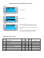
MenuA:On/OffUnit
o UnitAddress: 1(Default)
o Mode Cool,Heat,EH,OFF
o Status: Displayed
MenuB:Setpoints:
CoolCntrlSP:45F
o StageUp StageDown
o SP+1F >>‐0F
o SP+3F >>‐2F
HeatCntrlSP:110F
o StageUp StageDown
o SP‐1F >>+0F
o SP‐3F >>+2F
SeawaterPumpControl:ByDemand(Default)orByUnitOn(ContinuousOperation)
Configuration:
o TemperatureUnits:F(Default)OrC
o PressureUnits: PSI(Default)orBar
MenuC:Clock/Scheduler
o Date: Changedatehere.
o Hour: Changetimehere.
o Day: Displayed
NextScreen:
o DST: Enabled(Default)
o DescriptionFollows:
MenuD:Input/Output Viewvaluesorstatusofanalogsensors,digitalinputsorrelayoutputs.
o A:AnalogInputs:
o CWReturn
o InputB001:ActualValue
o ScrollforadditionalsensorvalueswithdownarrowbuttonthenESCtoexit.
o B:DigitalInputs:
o FlowSwitch
o DI3Status:ActualState(OpenorClosed)
o ScrollDownforadditionalactivedigitalinputs.Thiswillchangedependingonwhatisenabledinthesystem
configuration.
o C:RelayOutputs:
o SWPump

11
o Relay1Status:ActualState(ONorOFF)
o ScrollDownforadditionalactiverelayoutputs.Thiswillchangedependingonwhatisenabledinthesystem
configuration.
o D:AnalogOutputs:
o NOTUSED
MenuE:AlarmHistory
Willcapturethestatusofthefollowingparametersatthetimeofthealarm.Themostrecentalarmwillbeshown.Useuparrowtoto
viewpreviousalarms.
o Alarmwillbedisplayedfollowedby:
o CWReturn: Actualvalue
o CWSupply: Actualvalue
o SeaWater: Actualvalue
o ControlValue: Actualvalue
MenuF:BoardSwitch
Thismenuallowsyoutochangetoviewadditionalboardsandmakechangestothatparticularboard.Thisonlyappliestoamulti‐stage
configurationwhenunitsarenetworkedtogether.
o UnitAddress: 1(Default)
o Switchtounit: Desiredboardaddress
MenuG:Service
Somesubscreenswillrequireapassword.PleasecontactDometicforservicepassword.
Submenus:
SubMenuA:Information
o Theservicecontactinformationisavailableonthisscreen.
o Scrolltoviewadditionalfirmwareinformation.
o ThenextscreenwillcontaintheflashRAMinformation.
o Thenextscreenwillcontainthepowercyclestatuswhichindicateshowmanydaystheunithasbeenrunninginthelast
timeitwasturnedofforon.
o ThenextscreenwillcontaintheEvofirmwareinformation.
SubMenuB:Commission
o Onthisscreenthetechnicianwillbeabletoenterthedealercontactinformation.Thedefaultcontactinformationisthe
Dometiccontactinformation.Thentheuserwillselecttoupdatetheinformationbyselectingyesattheprompt.
o Thenscrolltothenextscreen.Onthescreentheuserwillbeaskedtocommissionthesystemandmustselectbetween
yesornothenpressenter.Thiswillsavetheinformationandoncecommissionthatthestatecannotbechanged.
SubMenuC:WorkingHours
o Compressor
o Runhours: Actual
o NumStarts: Actual

12
Scrolltonextscreenstoviewpumpandelectricheathours(optionalifinstalled).
SubMenuD:BMSConfig
UsedonlyforconfigurationsystemtoworkwithSTIICnetwork.
o BMSPort1
o Protocol:Carel
o Adddress 1(Default)
o BaudRate 19200(Default)
SubMenuE:TestMode
o TestMode: Disabled(Default)
o Timeout: Disabled(Default)
SubMenuF:ServiceSettings
SubSubMenuA:WorkingHourSet
o Compressor
o ServiceSetPoint: 0000h(Default) Canbeusedtosetaserviceintervalforsystem.Willdisplay
messageonscreen.
o ResettoZero? NO(Default).Usedtoresettherunhours
o Runhours: ActualValue. Usedtosettherunhoursifcompressororboardhasbeen
replaced.
Scrolltoviewadditionalitemssuchasthepumpsandelectricheatifinstalled.
SubSubMenuB:ProbeAdjustment
TempSensorCurve:Canselectadifferentsensorforretrofitsthathavethe30ksensor.
o CWReturn: 10k(Default)or30k
o CWSupply: 10k(Default)or30k
o SWInlet: 10k(Default)or30k
Tobeusedforcalibratingtheinstalledtemperaturesensorsorpressuretransducers.
o CWReturn
o InputB001
o Offsett 0.0(Default)
o Value ActualValue
Scrolltoviewadditionalanalogsensorsforcalibration.
SubSubMenuC:Thermoregulation
Thismenuallowsyoutosetthesuperheatsetpoint.
o Superheat
o CoolSetpoint: 10F(Default)
o HeatSetpoint: 10F(Default)
Nextscreen
o SetpointSH: 10F(Default)
o LowSHthresh: 2.0F(Default)
o LOPthresh: ‐30.0F(Default)

13
o MOPthresh: 82.4F(Default)
SubSubMenuD:UserSave
Thisisusedtosaveanyuserspecificsettings.
o Save? No(Default)Yes
o Restore? No(Default)Yes
o EnableAutoSave:Yes(Default)No
SubSubMenuE:StageAddress
Thismenuistobeusedinamultistageconfigurationtochangetheadditionalunitaddresses.Thisistobedoneso
thattherearenoaddressconflictswhendaisychainingtheadditionalunitmodbusconnections.Thismustbedone
priortoconnectingalltheunitstogether.
o pLANBoardAddressing
o CurrentAddress: 1(Default)
o ChangeAddressto:1(Default)
NextScreen
SystemSetup
o NumofStages 1(Default)Max6
SubSubMenu:FStageDisable
Thismenuistobeusedwheninamultistageconfiguration.Thisallowsatechniciantotakeastageoff‐linesothat
repairscanbemadeandtherestofthesystembeoperationalinautomode.Thesystemmustbeinanoffstateto
enablestagecontrol.
o Maintenance
o StageControl: No(Default)Yes.
IfEnabled,
o Stage1: Enabled(Default)Disabled
o Stage2: Enabled(Default)Disabled
o Stage3: Enabled(Default)Disabled
o Stage4: Enabled(Default)Disabled
SubMenuG:ManualManagement
Thismenuallowsthetechniciantomanuallyoperatetherelayoutputsaswellasenableordisableanalogsensors.
o SubSubMenuA:AnalogInput
o CWReturn
o ManualControlB001: Off(Default)On
o ManualPosition:ValueDesired
o Value: ActualValue
Scrolltoadjustadditionalsensors
o SubSubMenuB:DigitalInput
o FlowSwitch
o ManualDI3: Off(Default)ON
o ManualPosition: Actual(EnterDesiredPosition)
o DIInputStatus: ActualValue

14
Scrolltoadjustadditionalinputs
o SubSubMenuC:RelayOutput
o SWPump
o ManualRelay1: OFF(Default)No
o ManualPosition: OFF(EnterDesired)
o RelayStatus: ActualPosition
ScrolltoadjustadditionalOutputs
o SubSubMenuD:AnalogOutputs
o NOTUSED

15
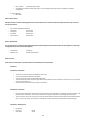
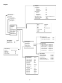
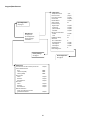
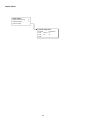
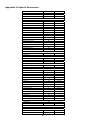
AppendixINavigationTree
MainStatusScreen
MainStatusScreen
CWSupplyTemp #.#°F
Mode Off/Cool/Heat/ElHt*
CWReturntemp #.#°F
CWSupplytemp #.#°F
ControlSensor #.#°F
Mode Off/Cool/Heat/ElHt*
PumpRelayOutputs
SWPump On/Off
CWPump On/Off
Chiller#1
CWreturntemp #.#°F
CWsupplytemp #.#°F
Flowstatus Ok/Alm/Off
HighpressurestatusOk/Alm/Off
ElectricHeat*Ok/Alm/Off
EHFL*Ok/Alm/Off
CompressorOk/Alm/Off
SupplyTemp
Chiller1 #°F
FlowDiagram
SuperHeat #°F
Compressor #°F
TXVOpen #%
Steps #stp
SuctionPressure #psi
SuctionTemperature#°F
Legend
*Asteriskindicatesthisitemisonlyviewablewhen
activatedinthefactorysettings.
Asolidboxmeansthatitisasubmenuofthe
menuandneedstobeaccessedbypressingenter.
Adottedboxisabreakoutoftheadditional
informationthatiscontainedbelowthatmenucategory.

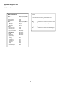
16
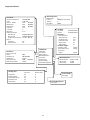
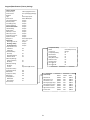
Program
Program
Setpoints
Clock
Input/Output
AlarmHistory
BoardSwitch
Technician
Manufacturer
AnalogOutput
ValvestatusStd‐by
Valveopening#.#%
Valveposition#stp
Coolcapacity#%
Superheat#.#°F
S1probe
Evap.Press#.#psig
Evap.Temp#.#°F
S2probe
SuctionTemp#.#°F
S1probe #.#psig
S2probe #.#°F
S3probe #.#psig
S4
p
robe #.#°F
Setpoints
Coolcontrol
Setpoint #°F
1‐StageUp #°F
1‐StageDown #°F
Heatcontrol
Setpoint #°F
1‐StageUp #°F
1‐StageDown #°F
SWPumpControl ByDemand/ByUnitOn
TemperatureUnits °F/°C
PressureUnits
p
si
/
bar
Clock/Scheduler
Date ##/##/##
Hour ##:##
Day #
DST Enable/Disable
Trans.Time #
Start #
End #
Input/Output
AnalogInput
DigitalInput
RelayOutput
AnalogOutputs
AnalogInput
CWReturnInputB001###
CWSupplyInputB002###
DigitalInput
HighpressureDI1Open/Close
LowpressureDI2Open/Close
WaterFlowDI3Open/Close
Open/Close
Open/Close
ElHeatFlowDI4
HandCoolDI6
HandHeatDI7Open/Close
RelayOutput
SWPumpRelay1 On/Off
CWPumpRelay2 On/Off
FaultRelay3On/Off
CompressorRelay7On/Off
ReversingValveRelay4On/Off
BoardSwitch
Unitaddress:##
Switchtounit:##
Technician
Seepage#
Manufacturer
See
p
a
g
e#
AlarmHistory
Alarm# AlarmMessage
CWReturn #
CWSupply #
Controlvalve #

17
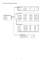
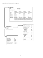
Program/Technician
BMSConfiguration
BMSPortNo.#
Protocol ######(scrolltoselect)
Address #
BaudRate #####
Technician
Information
Commission
WorkingHours
BMSConfiguration
Testmode
PumpControl
ServiceSettings
ManualManagement
Information
ServiceContactPhone###‐###‐####
Code: LEModule
Version&Date #.####/##/##
BIOS&Date #.####/##/##
Boot&Date #.####/##/##
FlashRam #Kb
Tmemory #
##Cycle/s #ms
PowerCycleStatus
LastOffTime ##/##/####:##:##
LastOnTime ##/##/####:##:##
LengthTimeoffDays:#Hrs:##Min:##
EVOno.
FWVersion #.#
ServiceVersion #.#
Commission
Entercontactinfo
Name ####
TelephoneNo. ###‐###‐####
Updateinfo? Yes/No
Commissiondate ##:####/##/##
Commissionsystem?Yes/No
WorkingHours
RunHoursNumberStarts
Compressor #h #
ReversingValve #h #
ChilledWaterPump#h #
SeawaterPump #h #
ElectricHeat #h #
ServiceSettings
Seepage#
ManualManagement
See
p
a
g
e#
TestMode
TestmodeEnabled/Disabled
Timeout Enabled/Disabled
Parameters*
Testmodetimers
Testmodetime ##s
Seawaterpump #m
Chillwaterpump #m
Stage1Comp #s
Stage2Comp #s
Testmodesettings*
Seawaterpump Yes/No
ChilledwaterpumpYes/No
Compressor
Stage1 Yes/No
CWPumpControl
ManualControlRelay2On/Off
ManualPos.On/Off
StatusValueOn/Of
f

18
Program/Technician/ManualManagement
ManualManagement
AnalogInput
DigitalInput
RelayOutput
Analo
g
Out
p
ut
AnalogInput
ManualControl ManualPos.StatusValue
CWReturnB001On/Off #.# #.#
CWSupply B002On/Of
f
#.# #.#
DigitalInput
ManualControl ManualPos.StatusValue
HighPressureDI1On/Off Open/CloseOpen/Close
LowpressureDI2On/Off Open/CloseOpen/Close
WaterFlowDI3On/Off Open/CloseOpen/Close
Loadshedding DI5On/Off Open/Close Open/Close
ElectHtFlow*DI4On/Off Open/Close Open/Close
HandCool DI6On/Off Open/Close Open/Close
HandHeatDI7On/Of
f
Open/Close Open/Close
RelayOutput
ManualControl ManualPos.StatusValue
SWPump Relay1On/Off On/Off On/Off
CWPumpRelay2On/Off On/Off On/Off
Fault Relay3On/Off On/Off On/Off
CompressorRelay7On/Off On/Off On/Off
Revvalve Relay4On/Off On/Off On/Off
ElectricHeat*Relay5On/Off On/Off On/Off
AnalogOutput
Enablemanualvalveposition*Yes/No
ManualValveposition* #stp

19
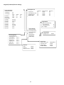
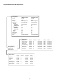
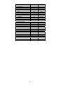
Program/Technician/ServiceSettings
StageAddress
pLANBoardAddressing
CurrentAddress #
ChangeAddressto#
No.ofStages #
ServiceSettings
WorkingHourSet
ProbeAdjustments
Thermoregulation
UserSave
StageAddress
StageDisable
S
y
stemSetu
p
ProbeAdjustments
TempSensorCurve
CWReturn#k
CWSupply#k
InputOffsetValue
CWReturnB001#.##.#
CWsupplyB002#.##.#
Probeadjust
S1offset #.#psig
S1probe #.#psig
S2offset #.#°F
S2probe #.#°F
S3offset #.#psig
S3probe #.#psig
S4offset #.#°F
S4
p
robe #.#°F
WorkingHourSet
SetPointResettoZero?RunHours
Compressor#hYes/No#h
ChilledWaterPump#hYes/No#h
SeawaterPump#hYes/No#h
ElectricHeat*#hYes/No#h
Thermoregulation
SuperheatSetpoint
CoolSetpoint#.#°F
HeatSetpoint#.#°F
SetpointSH#.#°F
LowSHthresh#.#°F
LOPthresh#.#°F
MOPthresh#.#°F
StageDisable
StageControlYes/No
SystemSetup
WaterLoopControlSupply/Return
HeatSupTempYes/No
ElectricHeatYes/No
EHFlowSwitch*Yes/No
UserSave
Save? Yes/No
Restore? Yes/No
EnableautosaveYes/No

20
Program/Manufacturer
Initialization
Thiswillclearthealarmhistorycontinue?Yes/No
InsertNewPasswords
User####
Technician(PW1) ####
Factory(PW2)####
FactorySave
Save?Yes/No
Restore?Yes/No
AutoRestore?Yes/No
UserSave
Save?Yes/No
Restore?Yes/No
AutoRestore?Yes/No
Defaultinstallation
Eraseusersettingandinstall
globaldefaultvalue? Yes/No
I/OConfiguration
Seepage#
Manufacturer
Configuration
I/OConfiguration
FactorySettings
Initialization
FactorySettings
Seepage#
Configuration
TemperatureUnits °F/°C
PressureUnits psi/bar
Forceclockenable Yes/No
Clockmode 24h/12h
DisableBuzzer Yes/No
Startupdelay #s
EnableUnitby
DigitalInput On/Off
Supervisor On/Off
pLANnetwork On/Off
Schedule On/Off
ManualControlReset
Enable Yes/No
Time #m
PW/ReturnDelay #s
Scheduler
No.ofSchedules #
OptimizedStart Yes/No
Set1Adjust Yes/No
Set2Adjust Yes/No
HolidaysNo. #
EVOConfigurator
EVOConfiguration
Seepage#
Page is loading ...
Page is loading ...
Page is loading ...
Page is loading ...
Page is loading ...
Page is loading ...
Page is loading ...
Page is loading ...
Page is loading ...
Page is loading ...
Page is loading ...
Page is loading ...
Page is loading ...
Page is loading ...
Page is loading ...
Page is loading ...
-
 1
1
-
 2
2
-
 3
3
-
 4
4
-
 5
5
-
 6
6
-
 7
7
-
 8
8
-
 9
9
-
 10
10
-
 11
11
-
 12
12
-
 13
13
-
 14
14
-
 15
15
-
 16
16
-
 17
17
-
 18
18
-
 19
19
-
 20
20
-
 21
21
-
 22
22
-
 23
23
-
 24
24
-
 25
25
-
 26
26
-
 27
27
-
 28
28
-
 29
29
-
 30
30
-
 31
31
-
 32
32
-
 33
33
-
 34
34
-
 35
35
-
 36
36


Dometic Basic Chiller Control Operating instructions
- Category
- Thermostats
- Type
- Operating instructions
Ask a question and I''ll find the answer in the document
Finding information in a document is now easier with AI