Page is loading ...

IMPORTANT: IN THE INTEREST OF PRODUCT PERFORMANCE AND SAFETY PLEASE READ THESE INSTALLATION AND WARRANTY INSTRUCTIONS BEFORE INSTALLING THE PRODUCT.
MANTIS SMS806WF MULTIFUNCTION SENSOR electrical and installation specification effective 23/7/2022.
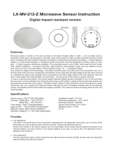
MUST BE INSTALLED
BY A LICENSED
ELECTRICIAN
DIY
Electrical classBeam angle
Dimension (L x W x H mm) Earth leakage current
Operating ambient min/max (°C) Storage ambient limit (°C)
Operating humidity Storage humidity
Calculated TM - 21, L
70
@ 85 °C (hrs)
70
@ 85 °C (hrs)Reported TM - 21,L
Aiming restrictions (if any) Product application
IK rating (if relevant)Product installation orientation
CCT (k) switch control (TC)Dimmable
Insulation cover rating (if any) PIXIE connectivity
N/A
Replaceable LED N/A IP rating
Attachment typeUser replaceable LED
IP rating for interior products: The designated IP rating is “from below the ceiling” unless otherwise specified.
IP rating ALL products; Termination of the product must be made in accordance with the IP rating.
Earth Leakage current: Is calculated in accordance with AS/NZS 60598.1:2017.
No
N/A
IP66
N/A
10% to 85% RH, NC
N/A
N/A
0 to 60
10% to 85% RH, NC
N/A
Class II
N/A
N/A
N/A
0 to 40
140 x 115 x 75
Refer dimension detail
N/A
Interior & exterior residential & commercial spaces
Ceiling or wall mount
SAL National Pty Ltd.
40 Biloela Street
Villawood NSW 2163 ABN 21 633 189 474
Copyright SAL V12 FEB 2020 |
www.sal.net.au
| Page 1 of 3
SAL products are designed in accordance with all mandatory International and Australian Standards, which require installation
in accordance with AS/NZS3000 by a qualified installer and regular cleaning and maintenance of the equipment. Products are
sold in accordance with the following instructions and SAL standard terms and conditions of sale, available via www.sal.net.au.
SMS806WF
SMS806WF/BK
Model No. Power (W) Input
(V)/(Hz)
Working
Humidity (RH)
Detection
Angle
Detection
Motion Speed
Detection
Distance (m)
Time
Setting
Light
Control (lux)
Sensor Mass
(N.W.g)
Body
ColourType
0~93%110°
0.6~1.5
(m/s)
10~200010s ~ 30min
PIR
or
PE
220
Grey
Black
Max. 18m at
installation heights
1.8m-2.5m
220-240/50
Due to continued product and information updates, product data sourced from sal.net.au shall not form part of any contract and or technical performance
guarantee unless expressly confirmed in writing by SAL at the time of order.
General product application requirements (if applicable) :
1. CCT or POWER selections (where supplied) – IMPORTANT, where CCT colour temperature or POWER selection switching is provided, it is important to switch OFF the
power before the selection is made, otherwise equipment damage may occur.
2. Recycling – SAL encourages recycling, please consider the environment when disposing of packaging, batteries & components.
3. Switching or test intervals – For optimum product performance, good design practice does not encourage 24/7 operation of lighting products without the provision
of a routine switching or regulatory test cycle. As a guide for continual operation installations, a twelve (12) hour duration for Industrial and Commercial applications
and a six (6) hour duration for Residential applications should be considered.
4. Product maintenance – In line with the relevant design standards and to protect your investment, it is important to have in place a routine cleaning program that
reflects the installation environment and maintains the product in a clean and functional condition.
IMPORTANT - The supply must be isolated before any product maintenance or cleaning is conducted. In addition, damage to ANY cable or cord supplied with the
product must be addressed as follows; For attachment type X having a specially prepared cable, if the external flexible cable is damaged, it must be replaced by an
equivalent cable exclusively available from the manufacturer or authorised installer. For attachment type Y, if the external flexible cable is damaged, it must be
exclusively replaced by an equivalent cable by the manufacturer or authorised installer. For attachment type Z, if the external flexible cable is damaged, the cable
cannot be replaced and the luminaire must be destroyed.
5. Adverse, corrosive and coastal installation environments – Unless the product is specifically designated for such applications in these installation instructions, which is
supported by a professional maintenance program; installation of equipment in such environments is not recommended.
6. Dimming products – Dimming circuits and product compatibility must be validated by the installer before installation; SAL cannot be responsible for third party
changes in dimmer compatibility.
7. Suspended products – For installation safety, any suspended products must NOT be installed in high air movement spaces or locations subject to impact.
8. Light source replacements – (Non-replaceable light sources) - The light source of the product is deemed not replaceable, when the product reaches its end of life,
the complete product must be replaced by a qualified installer. (Non-user replaceable light sources) - The light source of the product must only be replaced by the
manufacturer or qualified installer. Caution, risk of electric shock.
9. Interior downlights and sensors with remote drivers and electrical accessories – The mounting facilities provided for the device (if any), need only be utilized if in the
application of the product is required by AS/NZS3000. Drivers are not designed for installation environments that restrict conventional airflow.
10. Ripple injection, induced flicker (QLD & NSW regions) – Installations subject to off-peak ripple induced flicker, (which are beyond the manufactures control), should
strongly consider the use of circuit filtering products, or for interior downlight installations, the use of products designed to block the signal interferences, such as the
SAL SFI series.
11. Floodlight products – Unless nominated aiming restrictions or installation parameters apply, products are designed for installation environments between ground and
15 metres in height, subject to the desired optical performance being achieved. For floodlight installation environments that have restricted access (eg: columns and
roof-lines) which are subject to unstable electrical supply or electrical surges (which void warranty), consideration of the installation of an independent surge protector
is strongly recommended.
12. Emergency enabled products – In the interest of transport and safety, emergency products are supplied with the battery disconnected. In addition to specific
emergency commissioning instructions, this battery MUST be connected at the time of installation. Continual use in emergency mode greater than 240 hours without
recharge, will result in battery failure and void battery warranty.
Max. 500
Max. 1000
Max. 2000
(Idle 1W)

SAL National Pty Ltd.
40 Biloela Street
Villawood NSW 2163 ABN 21 633 189 474
Copyright SAL V12 FEB 2020 |
www.sal.net.au
| Page 2 of 3
13. Specific installation procedures (if any) - this device must be installed by a licensed electrician:
MANUAL OVERRIDE MODE
•How to activate override mode:
When the sensor is in automatic sensor mode and the light is ON, switch the wall switch twice(OFF-ON-OFF-ON) within 5 seconds, the sensor will turn ON-OFF-ON and
enter the override mode. The red indicator LED will then illuminate continuously, the sensor is now in an 8-hour override mode. After this period times out, the sensor will
return to the automatic operation mode.
•How to return to automatic sensor mode:
Switch off the wall switch, wait 10 seconds and then switch it back on, then the sensor will be back in automatic sensor mode.
IMPORTANT: If the power is off for LESS than 10 seconds, the override mode will remain.
•How to activate the photocell mode:
When the sensor is in automatic sensor mode and the connected load is ON, switch the controlling switch three times (OFF-ON-OFF-ON-OFF-ON) within 5 seconds, the
sensor will then revert to the photocell mode.
• Once the photocell mode activated, the red sensor indicator light will continually flash.
• In photocell mode, when the ambient light is daytime (>150LUX) the connected load turns off after 10 seconds and when the ambient light is night-time (<10LUX), the
connected load will operate continuously.
•How to return to automatic sensor mode:
Switch off the wall switch, wait 10 seconds and then switch it back on, then the sensor will revert to the automatic sensor mode.
IMPORTANT: If the power is off for LESS than 10 seconds, the photocell mode will remain. Need to power off 10 seconds before manually changIng from photocell to
override mode.
MANUAL PHOTOCELL MODE:
1. Pressing ON - turns the device ON. Allow warm up for 10 seconds, then the load and the indicator light will operate together.
2. Pressing OFF - turns the the device OFF.
3. Pressing the SENSOR button will activate the sensor mode, resulting in default settings of 10sec hold time, 100% distance sensitivity, daylight sensor disabled. After 10
seconds hold time, if no movement is detected, the connected load will turn off. Should movement be detected within the 10 seconds, another 10 seconds hold time
will be added from the time of the detection.
SENSITIVITY, HOLD TIME AND DAYLIGHT SENSOR buttons are used to change the default settings.
3.1 Pressing the HOLD (TIME) will achieve 10s, 30s, 1min, 5mins, 8mins and 20mins hold time.
3.2 Pressing the SENSITIVITY (SENS) button achieves LOW ≈ 8M, MEDIUM button ≈ 14m, HIGH button ≈ 18M .
3.3 Pressing the DAYLIGHT (LUX) button achieves < 10LUX(NIGHT), LOW button ≈ 25LUX, MEDIUM button ≈ 250LUX, HIGH button ≈ 500LUX, DAY/24H button =24 hour operation.
IMPORTANT - After changing any parameters, the load will turn on and off once to indicating the change.
4. Pressing the PHOTOCELL button will activate the photocell mode. The load will turn ON - OFF - ON once and then enter PHOTOCELL control mode. Photocell range is
<10 LUX (ON) to >150 LUX (OFF).
IMPORTANT: When changing from ANY mode to another mode on romote control, the load will turn ON and OFF as well as a “red” led light flash in the sensor lens, will
indicate the function has been changed.
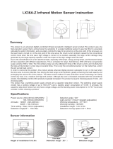
REMOTE CONTROL FUNCTIONS:
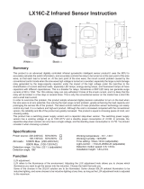
WIRING DIAGRAM
L
Lamp
Lo ut
Power cable Brown
(Sensor wire)
Blue
(Sensor wire)
White
(Sensor wire)
Power cable
Lamp wire
Lamp wire
LOAD
LOOP
• Daylight (LUX) threshold dial: Adjust the working state in different values of ambient light. The sensor can operate in the daytime and at night when it is adjusted to the
“LUX” position (max). It can operate in an ambient light less than 10LUX when it is adjusted to the “LUX” position (min).
• Sensitivity (SENS) dial: It can be adjusted according to application. The detection distance is a maximum of 18m.
• HOLD (TIME) dial: HOLD time is added continually. When it receives a second movement signal within the duration of the first detection, it will restart the time delay
from the second signal.
MANUAL SENSOR MODE:
OPTIONAL ACCESSORY - REMOTE CONTROL SMS806WF/RC
WARNING - KEEP BATTERIES OUT OF REACH OF CHILDREN
The remote control contains batteries, which if swallowed can
cause severe or fatal injuries. THE REMOTE CONTROL IS DESIGNED
FOR TRADE USE ONLY KEEP OUT OF REACH OF CHILDREN
OFF ON
PHOTOCELL
MODE
SENSITIVITY
L/M/H
SENSOR
MODE
DAYLIGHT
SENSOR
HOLD TIME
3. PRESS once, the sensor mode
will operate in default settings
as detailed below
3.2 SENSITIVITY (SENS) OPTIONS
LOW, MEDIUM, HIGH
3.3 DAYLIGHT (LUX) OPTIONS
NIGHT, LOW, MEDIUM, HIGH,
DAY/24h
1. PRESS once the load will turn ON
2. PRESS once, the load will turn OFF
4. PRESS once to activate the
PHOTOCELL MODE
3.1 HOLD (TIME) OPTIONS
10/30 seconds, 5/10/20/30 minutes
SMS806WF/RC
DIMENSIONS:
115 mm
75 mm
140 mm
IMPORTANT -
selection dials
must face down

SAL National Pty Ltd.
40 Biloela Street
Villawood NSW 2163 ABN 21 633 189 474
Copyright SAL V12 FEB 2020 |
www.sal.net.au
| Page 3 of 3
14. Warranty – In accordance with SAL’s standard terms and conditions of sale, SAL warrant this product to be free from defects in materials and or workmanship for a
period as stated below for goods not subject to incorrect installation, maintenance, operation, mishandling, environmental, unauthorised modifications or electrical
operating conditions outside the nominated product specification as detailed in these installation instructions. The benefits to you given by this warranty are in addition to
other rights and remedies you have under law. Our goods come with guarantees that cannot be excluded under the Australian Consumer Law. You are entitled to a
replacement or refund for a major failure and compensation for any other reasonably foreseeable loss or damage. You are also entitled to have the goods repaired or
replaced if the goods fail to be of acceptable quality and the failure does not amount to a major failure.
Warranty term – Residential usage (60) months, Commercial usage (60) months, Replaceable Lamps (where supplied) (12) months and Lithium batteries where supplied
(24) months from date of purchase. For New Zealand, please refer to www.sal.co.nz for warranty conditions and service.
How to make a claim?
Step # 1 – Within 30 days of the fault discovery, please contact the original place of the SAL product purchase during standard (local) business hours, with the following
information (a) proof of purchase (b) description and quantity of the claimed fault (c) address of installation. (d) operating hours of the product.
Step # 2 – It is then the responsibility of the original place of product purchase to report the matter to SAL aftersales;
NSW | ACT - SAL National Pty Ltd, 40 Biloela Street Villawood NSW 2163 | P # 02 9723 3099
QLD - SAL National Pty Ltd, 36 Whitelaw Place Richlands QLD 4077 | P # 07 3879 5999
VICT | TAS - SAL National Pty Ltd, 46-48 Keys Road Moorabbin Victoria 3189 | P # 03 9532 3168
SA | NT - SAL National Pty Ltd, Unit 1, 9 Alfred Avenue, Beverley SA 5009 | P # 08 7084 1958
WA - SAL National Pty Ltd, 29 Beringarra Av Malaga WA 6090 | P # 08 9248 7458
NZ - Hamer, 130 Bush Road, Albany, Auckland, 0632 | P # 0800 239 239
Step # 3 - Upon review of your claim and if the product is required to be returned to SAL for technical evaluation, then at the owners expense the product must be
returned to SAL as per the above nominated locations.
Step # 4 - Pending the evaluation, the claim will be validated resulting in the product being repaired or replaced with the same or best equivalent product at the
discretion of SAL, or rejected if the product fault was found to be caused by conditions beyond the responsibility of SAL warranty obligations. Consideration of
installation, product removal, return freight and or testing fees are not the responsibility of SAL.
• The connected load does not operate:
a. Check if the connected power source and load is correct.
b. Check if the settings of connected load correspond to ambient light.
• The sensitivity is poor:
a. Please check if there is any hindrance in front of the detector to affect it
to receive the signals.
b. Check if the ambient temperature is too high.
c. Check if the signal source is in the detection field.
d. Check if the installation height corresponds to the height required
in the instructions.
e. Check if the moving orientation is correct.
• The sensor does not turn off the connected load automatically:
a. Check if there is continual signal in the detection field.
b. Check if the time delay is set to the maximum position.
c. Check if the power corresponds to the instructions.
TROUBLE SHOOTING:
SENSOR DETECTION RANGE:
• Avoid pointing the sensor towards objects with highly reflective surfaces,
such as mirrors etc.
• Avoid mounting the sensor near heat sources, such as heating vents, air
conditioning units, light etc.
• Avoid pointing the sensor towards objects that may move in the wind,
such as curtains, tall plants etc.
INSTALLATION ADVICE - As the sensor responds to changes in temperature,
avoid the following situations:
5° tilt
2.5m
Max.18m
Max.18m
1. Turn the TIME dial anti-clockwise to the minimum (-).
2. Turn the SENS dial clockwise to the maximum (+).
3. Turn the LUX dial clockwise to the maximum (+).
4. Note: when testing in the daylight, please turn LUX dial to (Max) position,
otherwise the sensor will not operate.
5. Switch on the power; after Warm-up 30sec, the sensor will commence operating.
6. When the sensor receives the signal, the lamp will activate, whilst there is no
movement detected, the connected load will cease operating within 10sec.
7. Turn the LUX dial to the minimum (-). When the ambient light is MORE than 10LUX,
the sensor will not activate the load. When the ambient light is LESS than 10LUX
(darkness), if a movement is detected, the sensor load will commence operating.
if no movement detected, the sensor load will cease operating within 10 sec.
TEST AND COMMISSIONING:
TIME LUX SENS
/