Page is loading ...

CL-B101D40PF data sheet (d0110) Page 1
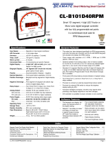
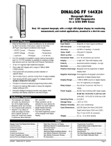
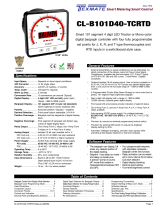
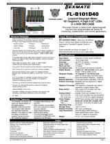
CL-B101D40PF
• ChoiceofDCvoltsorDCcurrent(headerselectable)
• Monocolor(redorgreen),101segmenthighbrightnessbargraph.
Verticaloroptionalhorizontalformat.
• Red4-digitLEDdisplaywitharangeof-0.50,1,+0.50
Optionalgreendigitaldisplay.
• Auto-sensingAC/DCpowersupply.Forvoltagesbetween
85-265VAC/95-300VDC(PS1)or18-48VAC/10-72VDC
(PS2).
• 24VDCexcitationisavailabletopowerexternal4/20mA
transmitters.
• Provisiontoconnectanexternalprogramminglockoutswitch.
• ProvisionforexternalDIMswitchtoreducethebrightest
displaysettingby50%.
• Automaticintelligentaveraging,smoothsnoisysignalswhile
providingafastdisplayresponsetoreallevelchanges.
General Features Specifications
Software Features
BargraphCenterPointDisplayModeSelection... 5
CaseDimensions ....................... 7
ComponentLayout...................... 7
ConnectorPinouts ...................... 6
Connectors............................ 6
ControlsandIndicators.................. 2
ProgrammingConventions................ 2
SoftwareFeatures...................... 1
SoftwareLogicTree ..................... 3
Specifications.......................... 1
TwoPointDigitalCalibrationMode......... 4
DecimalPointandBrightnessSelection..... 5
DigitalSpanSelectionforDisplay.......... 5
GeneralFeatures....................... 1
Installationguidelines .................... 7
OrderingInformation.................... 8
PinDescriptions ........................ 6
LEOPARD
FAMILY
Table of Contents
This unit accepts an analog DC signal from a
Power Factor transducer, ranging from 4-20mA,
0-1mA, 2VDC, 5VDC, and 10VDC.
It provides a bargraph and digital display of the
reading in the format customary for Power Factor
meters, with the bargraph centered at PF=1.0.
Lead and lag are indicated by the circular
bargraph extending clockwise (lead) or counter
clockwise (lag) with cos(theta) scale markings
from LAG 0.5 to 1.0 to LEAD 0.5.
The digital display provides a corresponding
numeric readout of the same data with LAG
represented by a negative sign.
• Bargraphcenterzerofunction.
• Digitaldisplayblanking.
• Four-levelbrightnesscontrolaccessedbythe button
andadjustedbythe button.
Input Specs:��������������•Headerselectablecurrentorvoltageinput
signal
•Currentinput:4-20mAwithshunt100ohm;
2mArangewithshuntresistance1kohm;
(Voltageatfullscalecurrentinput:2V�)
•Voltageinput:2V,5V,10V,inputimped-
ance1Mohm
A/D Converter:����������14bitsingleslope
Accuracy:������������������±(0�05%ofreading+2counts)
Temp. Coeff�:�������������100ppm/°C(Typical)
Warm up time:�����������2minutes
Conversion Rate:������10conversionspersecond(Typical)
Digital Display:����������
4 digit 0.56" LED red (std),green(optn)
Bargraph Display:�����
101 segment 235º circular red (stan-
dard),Green(optional)
Power Supply:�����������AC/DCAutosensingwiderangesupply
PS1 (std)����������������
85-265 VAC / 95-300 VDC, 50-400Hz 4.2W
PS2�������������������������
18-48VAC/10-72VDC,50-400Hz4�2W
Operating Temp�:������0to50°C
Storage Temp:�����������–20°Cto70°C
Relative Humidity:����95%(noncondensing)
Case Dimensions:����
Bezel(4�48"x4�48")113�8x113�8mm
Depthbehindbezel(4�23")107�46mm
Plus(0�48”)12�24mmforconnectors
Weight:�����������������������16oz�,1lb4ozwhenpacked

Page2 CL-B101D40PF data sheet (d0110)
101 Segment
Bargraph
Front Panel Buttons
Program Button
The
P
buttonisusedtomovefromoneprogramsteptothenext.
When pressed at the same time as the button, it initiates the
calibration mode.
Up Button
Whenintheoperationaldisplay,pressingthe buttonallowsyou
toviewthesettingofthesaved Peak and Valley Values.
When setting a displayed parameter during programming, the
buttonisusedtoincreasethevalueofthedisplayedparameter.
Down Button
Whenintheoperationaldisplay,pressingthe buttonallowsyou
tochangethe Brightness Level.
When setting a displayed parameter during programming, the
buttonisusedtodecreasethevalueofthedisplayedparameter.
Front Panel LED Display
Digital LED Displays
The digital LED displays are used to display the meter input
signal readings. They also display the programming settings
duringprogramming.
Controls and Indicators
Thissymbolrepresentsthe
OPERATIONALDISPLAY.
ThisisthePROGRAMbutton.
ThisistheUPbutton.
ThisistheDOWNbutton.
When a button is shown, press and
releaseit togoonto the nextstep in the
direction indicated by the arrow. When
an alternative dotted line is shown, this
indicates that an alternative logic branch
will be followed when a particular option
ispresent.
Whentwobuttonsareshownsidebyside
andenclosedbyadottedline,theymust
bepressedatthesametimethenreleased
togoontothenextprogrammingstep.
IfanXappearsthroughadigit,itmeansthat
anynumberdisplayedinthatdigitisnotrel-
evanttothefunctionbeingexplained.
P
[Span]
[1000]
P
P
When the
and
buttons are shown
together,thedisplayvaluecanbeincreased
by pressing and releasing the
button
ordecreasedbypressingandreleasingthe
button.
When the
and
buttons are shown
with two displays, either display can be
selectedbypressingandreleasingthe
or
buttons.
When two displays are shown together
withbursts,thisindicatesthatthedisplayis
toggling(flashing)betweenthenameofthe
functionandthevalue.
Text or numbers shown between square
brackets in a procedure indicate the pro-
grammingcodenameofthefunctionorthe
valuedisplayedonthemeterdisplay.
Whentherearemorethantwodisplayselec-
tionstheyareshowninbracketsbelowthe
first display and are also selectable by
pressingandreleasingthe
or
buttons.
A dotted line enclosing an entire logic dia-
gram indicates that programming branch
willappear onlywhen aparticular optionis
present.
Toexplainsoftwareprogrammingprocedures,logicdiagramsare
usedtovisuallyassistinfollowingtheprogrammingsteps.The
followingsymbolsareusedthroughoutthelogicdiagramsto
representthebuttonsandindicatorsonthemeter:
Programming Conventions
[X•XXX]
[XX•XX]
[XXX•X]
[XXXX•]
[XXXX]
Front Panel Controls and Indicators
UP
Button
DOWN
Button
PROGRAM
Button
7 Segments
Digital
Display

CL-B101D40PF data sheet (d0110) Page3
TheCL-B101D40PF is anintelligent bargraphmeter witha hier-
archical software structure designed for easy programming and
operation,asshownbelowinthesoftwarelogictree.
Software Logic Tree
Software Version is Displayed on Power-up
Whenpowerisapplied,allsegmentsofthebargraphanddig-
italdisplaylightupfor3seconds.Theversionnumberofthe
installedsoftwareisthendisplayedfor2seconds,afterwhich,
theoperationaldisplayindicatestheinputsignal.
15 Second Program Timeout
ExceptforZEROandSPANsettingsintheTwoPointDigitalCalibrationMode
andtheAnalogOutputRangeSettingandCalibrationMode(cLoandchi),the
meter has a 15 second program timeout. If no buttons are pressed for 15
secondsinanyoftheotherprogrammingsequences,themeterwillexitthe
programmingmodeandreturntotheoperationaldisplay.Anyprogramchang-
esthatweremadepriortopressingthe
P
buttonintheprecedingstepwill
notbesaved.
Peak
[PEAK]
Reset
PEAK
Reset
VALY
Valley
[VALY]
[orAn]
[rEd]
NOTE: Will only
appear if a tricolor
display is installed
[orAn]
[rEd]
[orAn]
[rEd]
[orAn]
[rEd]
[orAn]
[rEd]
BARGRAPH COLOR
PROGRAMMING MODE
See Page 9
Tricolor Bargraph
The tri-color bargraph is
designed like a traffic light, to
display either red, orange or
green, but only one color at a
time. The color to be displayed
is selected in two ways.
The first step is to select the
color to be displayed when the
bar is “below” whichever set
point is set to the lowest
position.
The second step is to select the
color to be displayed when the
bar is above each specific
setpoint, regardless of the order
or position to which the set
points are set.
However, if two or more
setpoints with differently
specified colors are positioned
at the same set point value, the
color specified for the set point
with the highest identifying
number will be displayed. When
setpoints are set to the same
value, the SP4 color overrides
the SP3 color, the SP3 color
overrides the SP2 color, and the
SP2 color overrides the SP1
color.
Set Setpoint 1
[SP1]
Delay-on-Make
[doM]
Delay-on-Break
[dob]
Relays
Activation
[rLYS]
(h) High the
relay
energizes
when the
setpoint is
exceeded.
(L) Low
the relay
energizes
below the
setpoint.
Setpoint 2
[SP2]
Setpoint 2
[SP2]
Setpoint 1
[SP1]
Setpoint 3
[SP3]
NOTE: [dom] [dob]
Functions are only
available for SP1
0 to 9999
seconds
0 to 9999
seconds
Pump
[PUM]
Hysteresis
[hYSt]
Hysteresis
[hYSt]
Bar Color
[coL]
Hysteresis
[hYSt]
Hysteresis
[hYSt]
Setpoint 3
[SP3]
Setpoint 4
[SP4]
Setpoint 4
[SP4]
Operational Display
MAIN MENU
PEAK & VALLEY
VIEW & RESET
BRIGHTNESS AND
SETPOINT VIEW MODE
Bargraph Center Point
Display Selection [cto]
Select [on]
This branch will
only appear if
the analog
output option
is installed
Back to
Operational
Display
Digital Display
ON/OFF
Selection [diSP]
Sub-menu MODE
Calibration Mode
Calibration
Input
Calibration
Output
Calibrate Analog
Output Low
[cLo]
Calibrate Analog
Output High
[chi]
Select the Digital
Reading at which
the Analog Output
Hi [chi] will occur
Select the Digital
Reading at which
the Analog Output
Lo [cLo] will occur
This branch will only appear
if the analog output option
is installed
DIGITAL SPAN SELECTION
FOR ANALOG RANGE OUTPUT
See Page 6
DIGITAL DISPLAY ON/OFF
See Page 5
BARGRAPH CENTER POINT
DISPLAY MODE SELECTION
See Page 6
TWO POINT ANALOG OUTPUT
RANGE SETTING AND CALIBRATION
See Page 7
Set the Decimal
Point [dp]
Select [XX•XX]
Bargraph Display
Scale Lo Range
Setting [bLo]
Adjust to: 50
Bargraph Display
Scale hi Range
Setting [bhi]
Adjust to: 150
Display
Brightness [br]
1 Dimmest
2 Dim
3 Bright
4 Brightest
[X•XXX]
[XX•XX]
[XXX•X]
[XXXX•]
[XXXX]
DECIMAL POINT AND
BRIGHTNESS SELECTION
See Page 5
DIGITAL SPAN SELECTION
FOR BARGRAPH DISPLAY
See Page 5
Apply: Low Input
Adjust to: 50
Apply: High Input
Adjust to: 150
Any new settings
are canceled and
previous settings
are retained
Err. Indicates
unsuccessful
calibration
Goes directly
to Zero setting
if Analog Output
is not installed
TWO POINT DIGITAL
CALIBRATION MODE
See Page 4
+
–
4.00
+
–
20.00
1 Dimmest
2 Dim
3 Bright
4 Brightest
SETPOINT SETTING AND
RELAY CONFIGURATION MODE
See Page 8
L or h
L or h
L or h
L or h
Display
Brightness
[br]
Pump On Pump Off
When PUM is selected ON,
and SP2 is set at a value
higher than SP1, the SP1
relay will operate in
a special "pump on pump off"
Hysteresis mode. SP2 acts
as the upper limit and SP1
acts as the lower limit of the
Hysteresis Band.
For filling applications, rLYS
should be set to LhLh. SP1 will
then activate for inputs less than
the SP1 setpoint, and remain
ON until the SP2 setpoint is
reached.
For emptying applications,
rLYS should be set to hhhh.
SP1 will then activate for inputs
greater than the SP2 setpoint,
and remain ON until the SP1
setpoint is reached.
Note: The functions in grayded area
are not applicable for this model.

Page4 CL-B101D40PF data sheet (d0110)
STEP A Enter the Calibration Mode
1)
Press the
P
and buttons at the same time. Display
togglesbetween[CAL]and[oFF].
2) Pressthe or button.Displaychangesfrom[oFF]
to[on].
3)
Pressthe
P
button.
Displaytogglesbetween[ZEro]and
the previous zerosetting.
STEP B Set the Meter’s Low Input Signal Reading on the Digital
Display
1) Applyalowsignaltothemeter.
2) Usingthe and buttons,adjustthemeterdisplayto
[
50
]
readingfortheappliedlowinputsignal.
3) Press the
P
button. Display toggles between [SPAn]
andthepreviousspansetting.
STEP C Set the Meter’s High Input Signal Reading on the Digital
Display
1) Applyahighinputsignaltothemeter.
2) Usingthe and buttons,adjust thedigitaldisplay
to
[
150
]
readingfortheappliedhighinputsignal.
3) Pressthe
P
button.
The Digital Calibration Procedure is now complete.
Ifthedigitalcalibrationwassuccessfullycompleted,the menu
branchestotheDigitalSpanSelectionforBargraphDisplay,and
thedisplayflashes[bhi]andtheprevioussetting.
ERROR Indicates Unsuccessful Calibration
If the calibration was unsuccessful, the display indicates
[Err],thenewcalibrationsettingsjustenteredwillnottake
effect and the previously stored setting will remain.
The
threemostlikelycausesofanerrorduringcalibrationare:
1.
The full scale and zero signals were too similar. The full scale
signalmustbeatleast1000countsgreaterthanthezeroorlow
inputsignal(positiveandnegativevaluesareallowed).
2. Thescalingrequirementexceededthedigitaldisplayspan
capability of the meter (12,000 counts between –1999 to
9999).
3. Noinput signalpresent,orincorrectinput signalconnec-
tions.
Two Point Digital Calibration Mode
MAIN MENU
Operational Display
Sub-menu
MODE
STEP A Calibration
Mode
STEP B Zero
STEP C Span
Err. Any new setting
canceled and previous
settings are retained
To Digital Span Selection for
Bargraph Display
TWO POINT DIGITAL
CALIBRATION MODE
To Digital Span Selection
for Bargraph Display
Apply: Low Input
(Ex.4mA)
Adjust to: 50
Apply: High Input
(Ex. 20 mA)
Adjust to: 150

CL-B101D40PF data sheet (d0110) Page5
From Two Point
Digital Calibration
Mode See Page 4
STEP A
STEP B
STEP C
STEP D
To Bargraph Center Point
Display Mode Selection
DIGITAL SPAN SELECTION
FOR BARGRAPH DISPLAY
[X•XXX]
[XX•XX]
[XXX•X]
[XXXX•]
[XXXX]
DECIMAL POINT AND
BRIGHTNESS SELECTION
Bargraph Display
Scale Lo Range
Setting [bLo]
Adjust to: 50
Bargraph Display
Scale hi Range
Setting [bhi]
Adjust to: 150
Set the Decimal
Point [dp]
Select [XX•XX]
STEP A Enter the Calibration Sub Menu Mode
1) Pressthe
P
and buttonsatthesametime.Displaytoggles
between[CAL]and[oFF].
2) Press the
P
button. Display toggles between [bhi] and the
previous setting.
STEP B Set the Digital Span of the Bargraph Display
1) Usingthe and buttons,adjustthedisplayto[150]
highparameterreading.
2) Press the
P
button. Display toggles between [bLo] and the
previoussetting.
3) Using the and buttons, adjust the display to [50] low
parameterreading.
4) Pressthe
P
button.Displaychangesfrom[50]to[dP].
STEP C Set the Decimal Point
1) Usingthe and buttons,adjustthedisplaytothe
[XX.XX] decimalpointsetting.
2) Pressthe
P
button.Displaytogglesbetween[br]andthe
previousbrightnesssetting.
STEP D Set the Bargraph and Digital Display Brightness
1) Usingthe and buttons,adjustthedisplaytothe
desiredbrightnesssetting(4isthebrightestsetting).
2) Pressthe
P
button.Displaytogglesbetween[Cto]and[oFF]
.
Digital Span Selection For Bargraph Display
Decimal Point and Brightness Selection
Bargraph Center Point Display Mode Selection
STEP G
Bargraph Center Point Mode Selection (See example above)
1) Toselectbargraphcenterpointmode,pressthe or
button.Displaychangesfrom[oFF]to[on].
2) Pressthe
P
button.Displaytogglesbetween[diSP]and
[on]or[oFF].
STEP H Digital Display ON/OFF Selection
1) Tosetthedisplayto[oFF],pressthe or button.
Displaytogglesbetween[diSP]and[oFF].
2) Pressthe
P
button.Thedisplayexitsthecalibrationmode
and returns to the operational display. Only the bargraph
displayisonandthedigitaldisplayisoff.
Ifthedigitaldisplayisselectedtobeoff,pressinganybuttonto
makeprogrammingchangesortoviewsetpointsactivatesthedigitaldisplay.
Whenthe procedure iscomplete, the digitaldisplay willthen automatically
switchoff.
The Display/Bargraph settings are now complete.
Operational Display
STEP G
STEP H
From Decimal Point
and Brightness Selection
BARGRAPH CENTER POINT
DISPLAY MODE SELECTION
Bargraph Center Point
Display Selection [cto]
Select [on]

Page6 CL-B101D40PF data sheet (d0110)
Pinout Diagram
TheCL-B101D40usesplug-intypescrewterminalconnectorsfor
allinput andoutputconnections�The powersupplyconnections
(pins14and15)haveauniqueplugandsocketoutlinetoprevent
cross connection� The main board and input signal conditioner
useright-angledconnectorsasstandard�Theoutputmoduleuses
straight-thruconnectorsasstandard�
WARNING: AC and DC input signals and power supply
voltages can be hazardous. Do Not connect live wires to
screw terminal plugs, and do not insert, remove or handle
screw terminal plugs with live wires connected.
17 16
14 158 9 10 11
See Leopard Family Input
Signal Conditioning Modules
1 2 3 4 5 6
21 20 19
Relay Outputs Reserved for RS-485
LOCK
COMMON
No Function
DIM
ANALOG
OUTPUT –
AC
Neutral
– DC
AC
Line
+ DC
ANALOG
OUTPUT +
29 28 27 26 25 24 23 22
Input Signal – Pins 1 to 6
Pins1to6arereservedfortheinputsignalconditioner�
Seethedatasheetfortheselectedinputsignalconditioner�
Rear Panel Function – Pins Pins 8 to 11
Pins 8 to 11providefunctionsthatcanbeimplemented
withanexternalswitch�Theirpindefinitionsare:
Pin 11 DIM.Byconnectingthedisplaydim(DIM)pinto
theCOMMONpin,thedisplaybrightnesssetting
ishalved�
Pin 10 COMMON.ToactivatetheLOCKorDIM
functionsfromtherearofthemeter,the
respectivepinshavetobeconnectedtothe
COMMONpin�Thispinisconnectedtothe
internalpowersupplyground�
Pin 9 No function
Pin 8 LOCK. ByconnectingtheLOCKpintothe
COMMONpin,themeter'sprogrammed
parameterscanbeviewedbutnotchanged�
Connector PinoutsConnector Pinouts
Pin Descriptions
AC/DC Power Input – Pins 14 and 15
Auto-sensingAC/DCpowersupply�Forvoltages
between85-265VAC/95-300VDC(PS1)or
18-48VAC/10-72VDC(PS2)�
Pin 14 AC/DC Neutral.Neutralpowersupplyline�
Pin 15 AC/DC line.Livepowersupplyline�
Standardplug-inscrewterminalblocksprovidedbyTexmate:
WARNING
AC and DC input signals and power
supply voltages can be hazardous.
Do Not connect live wires to ter-
minal blocks, and do not insert,
remove or handle terminal blocks with live
wires connected.
Connectors
Note:Grayshadedareaisnotapplicabletothismodel.

CL-B101D40PF data sheet (d0110) Page7
101.60
4.000
42.85
1.687
42.85
1.687
42.85
1.687
42.85
1.687
6.50
0.256
113.79
4.480
113.79
4.480
56.90
2.240
56.90
2.240
17.50
0.689
97.77
3.849
119.70
4.713
13.70
0.539
1/4"-28UNF
Panel Cutout
5.0
0.197
R4
0.157
16.30
0.642
13.70
0.539
4.80
0.189
screw-10-32 UNF
8
0.315
7
0.276
16.30
0.642
13.70
0.539
2.60
0.102
6.32
0.249
screw-1/4”-28 UNF
Case Dimensions
Component LayoutComponent Layout
INPUT MODULE
24V
Exc
IP07: Universal Process Input
2V/5V/10V/20V/200V/2mA/20mA/Custom
Custom
20mA
2mA
200V
20V
10V
5V
2V
VOLTAGE
CURRENT
UNIVERSAL PROCESS
Process input
Requires Digital Calibration
HI
LO
OFF ON
24V EXC
224C
InputRangeHeader
(IP07)
24VExc�on/offHeader
SignalTypeHeader
Voltage/Current
Installation Guidelines
1�Installandwiremeterperlocalapplicablecodes/reg-
ulations,theparticularapplication,andgoodinstallation
practices�
2�Installmeterinalocation that does notexceedthe
maximum operating temperature and that provides
goodaircirculation�
3� Separate input/output leads from power lines to
protect the meter from external noise� Input/output
leads should be routed as far away as possible from
contactors,controlrelays,transformersandothernoisy
components�Shieldingcablesforinput/outputleadsis
recommended with shield connection to earth ground
nearthemeterpreferred�
4�A circuit breaker or disconnect switch is required to
disconnect power to the meter� The breaker/switch
shouldbeincloseproximitytothemeterandmarkedas
thedisconnectingdeviceforthemeterormetercircuit�
Thecircuitbreakerorwallswitchmustberatedforthe
appliedvoltage(e�g�,120VACor240VAC)andcurrent
appropriate for the electrical application (e�g�, 15A or
20A)�
5�SeeCase Dimensions section for panel cutoutinfor-
mation�
6�SeeConnector Pinouts sectionforwiring�
7�Use28-12AWGwiring,minimum90˚C(HH)tempera-
turerating�Stripwireapproximately0�3in�(7-8mm)�
8�Recommendedtorqueonallterminalplugscrewsis
4�5lb-in(0�51N-m)�

Page 8 CL-B101D40PF data sheet (d0110)
CL-B101D40PF
Add to the basic model number the order code suffix for each standard option required. The last suffix is to
indicate how many different special options and or accessories that you may require to be included with this product.
Ordering Example: CL-B101D40PF-VRR-PS1-IP01-OA1 plus ZR
Ordering Information
WARRANTY
Texmatewarrantsthatitsproductsarefreefromdefectsinmaterialandworkmanshipunder
normaluseandserviceforaperiodofoneyearfromdateofshipment.Texmate’sobligations
underthiswarrantyarelimitedtoreplacementorrepair,atitsoption,atitsfactory,ofanyof
theproductswhichshall,withintheapplicableperiodaftershipment,bereturnedtoTexmate’s
facility, transportation charges pre-paid, and which are, after examination, disclosed to the
satisfactionofTexmatetobethusdefective.Thewarrantyshallnotapplytoanyequipment
which shall have been repaired or altered, except by Texmate, or which shall have been
subjectedtomisuse,negligence,oraccident.InnocaseshallTexmate’sliabilityexceedthe
original purchase price. The aforementioned provisions do not extend the original warranty
periodofanyproductwhichhasbeeneitherrepairedorreplacedbyTexmate.
USER’S RESPONSIBILITY
We are pleased to offer suggestions on the use of our various products either by way of
printedmatterorthroughdirectcontactwithoursales/applicationengineeringstaff.However,
sincewehavenocontrolovertheuseofourproductsoncetheyareshipped,NOWARRANTY
WHETHER OF MERCHANTABILITY, FITNESS FOR PURPOSE, OR OTHERWISE is made
beyondtherepair,replacement,orrefundofpurchasepriceatthesolediscretionofTexmate.
Usersshalldeterminethesuitabilityoftheproductfortheintendedapplicationbeforeusing,
and the users assume all risk and liability whatsoever in connection therewith, regardless
ofanyof oursuggestionsor statementsasto applicationorconstruction. Inno eventshall
Texmate’sliability,inlaworotherwise,beinexcessofthepurchasepriceoftheproduct.
Texmate cannotassume responsibilityfor anycircuitrydescribed. No circuitpatentor soft-
warelicensesareimplied.Texmatereservestherighttochangecircuitry,operatingsoftware,
specifications,andpriceswithoutnoticeatanytime.
BASIC MODEL NUMBER
CL-B101D40PF
114x114mm, 101 Segment Circular Bargraph with 4 Digit
Display .........................................
Standard Options for this Model Number
Order Code Suffix Description List
DISPLAY
RR......Red Circular 101 Segment LED Bar with 4 Digit Red LED Display ........
GR ...
Green Circular 101 Segment LED Bar with 4 Digit Red LED Display .....
POWER SUPPLY
PS1 .....85-265VAC/95-300VDC ...........................................
PS2 .....18-48VAC/10-72VDC . . . . . . . . . . . . . . . . . . . . . . . . . . . . . . . . . . . . . . . . . . . . . .
INPUT MODULES
(Partial List. See www.texmate.com)
IP07 ....Universal Process 2V/5V/10V/20V/200V/2mA/20mA/Custom
.............
Special Options and Accessories
Part Number Description List
SPECIAL OPTIONS
(Specify Inputs or Outputs & Req. Reading
)
ZR ............... Range change from Standard Range shown in BOLD Type .......
ACCESSORIES
(Specify Serial # for Custom Artwork Installation)
93-PLUG2P-DP...... Extra Screw Terminal Conn., 2 Pin Power Plug ...............
93-PLUG2P-DR ..... Extra Screw Terminal Conn., 2 Pin Plug.....................
93-PLUG3P-DR ..... Extra Screw Terminal Conn., 3 Pin Plug.....................
93-PLUG4P-DR ..... Extra Screw Terminal Conn., 4 Pin Plug.....................
93-PLUG5P-DR ..... Extra Screw Terminal Conn., 5 Pin Plug.....................
Prices subject to change without notice
1934KelloggAve�,Carlsbad,CA92008
Tel:1-760-598-9899•1-800-TEXMATE•Email:orders@texmate�com
CL-B101D40PF Technical Manual Copyright © 2021 Texmate Inc. All rights
reserved. Published by: Texmate Inc. USA. Information in this Technical Manual
is subject to change without notice due to correction or enhancement. The
information described in this manual is proprietary to Texmate, Inc. and may
not be copied, reproduced or transmitted, in whole or in part, in connection with
the design, manufacture, or sale of apparatus, device or private label product
without the express written consent of Texmate, Inc.
BASIC MODEL #
DISPLAY
POWER SUPPLY INPUT MODULES ANALOG OUTPUT RELAY OUTPUT OPTIONS / ACCESSORIES
OA____
/
