Toolots BP585 User manual

Type
User manual

Toolots BP585 is a versatile tire changer designed for efficient and safe tire mounting, demounting, and servicing of truck tires. With a maximum wheel weight capacity of 1000Kg and a maximum wheel diameter of 1300mm, it can handle a wide range of truck tire sizes, including 17.5", 19.5", and 22.5". The hydraulic motor, with a torque of 640Nm, provides ample power for effortless tire handling. The user-friendly operation console allows for precise control of the main shaft, jaws, and bead press roller, ensuring smooth and accurate tire changes.

Toolots BP585 is a versatile tire changer designed for efficient and safe tire mounting, demounting, and servicing of truck tires. With a maximum wheel weight capacity of 1000Kg and a maximum wheel diameter of 1300mm, it can handle a wide range of truck tire sizes, including 17.5", 19.5", and 22.5". The hydraulic motor, with a torque of 640Nm, provides ample power for effortless tire handling. The user-friendly operation console allows for precise control of the main shaft, jaws, and bead press roller, ensuring smooth and accurate tire changes.

User Installation, Operating and
Service Manual
User Installation, Operating and
Service Manual
Manuale d’uso
Ita
Fra
Deu
Spa
Eng
Manuel d’utilisation
Betriebsanleitung
Manual de uso
1
Main components Refer to FIG.01
Vertical column slider
Demounting tool head
Bead pressing roller
Rotation main shaft
Main shaft tilting cylinder
Operation console
Lube container support ring
FIG.01
Technical specifications
Suitable truck rim size 17.5 19.5 22.5
Max. wheel weight 1000Kg
Max. wheel width 425
Max. wheel diameter 1300
Hydraulic motor BMP315 640Nm
Hydraulic pump
station motor
3KW-380V-3PH
Operation pressure 130 bar -150bar
Noise level 75db
Net weight 500Kg
Installation
To select safe site according to relevant
safety rules. The tire changer needs to connect
to the power supply. It should choose a place
that is convenient for power connection and
the installation space that is convenient for
operators to operate
Refer to FIG.02 dimension
layout. If installed outdoors, the ma chine
must be provided with a shed from rain.
FIG.02
Installation base, refer to FIG.03 The installation ground
must be flat. With through-holes at the base of the machine
chassis. Fasten with bolts. When the slope relative to the
horizontal level is greater than 2.5‰, it should be levelled to
achieve compensation.
FIG.03
2
Power connection
Pay attention to
The installation site shall be equipped with an effective
protective grounding circuit and make the ground
connection according to the machine ground mark.
The power system should be equipped with automatic
circuit breakers. Set it at 30A.
Connect the tire changer to the power supply, close the
switch and check the motor. Is it running in the same
direction as the arrow indication direction?
R efer to FIG.05 . If the operation direction is opposite,
and the phase line must be switched by professionals.
Note Both the main shaft motor and the hydraulic pump
station motor are equipped with overload protection
device installed in the electric control box in Fig. 4
Running test
A running test must be carried out before the tire changer is
used to check the installation and operation is ok.
All the following work must keep the bead pressing
roller (item No.3) under the condition of being not in
work.
Connect the power supply to control console( item No.6)
turn on the main power switch and the hydraulic pump
station motor starts. Pull the joystick B downwards:
vertical column slider moves downwards. Pull the
joystick B upwards: vertical column slider moves
upwards.
Operation controlP ull upwards the joystick switch A
that controls the main shaft chuck to run
counterclockwise. Pull downwards the joystick switch A
that controls the main shaft chuck to run clockwise. Pull
the joystick C upwards the main shaft chuck tilts
upwards. Pull the joystick C downwards, the main shaft
chuck tilts downwards. Pull the joystick D upwards, and
the jaws open. Pull the joystick D downwards, the jaws
close.
The up-and-down movement of the tire changing tool
arm and the opening of the hydraulic clamp can cause
bruise, so the operator has to work outside its
movement range.
When the demounting truck wheel weight exceeds 1000Kg,
the machine must be fixed with anchor bolts.
If the motor keeps reverse running for several
seconds, it may burn out!
All electrical operations must be carried out by
professional technicians!
Fig6
Fig5
Fig4
3
Operation
Operation instruction
Ignoring instructions and warnings can cause serious
trauma to the operator or third party. So don't turn it
on until you have read this manual.
All operators must be properly trained before using the
machine (other personnel are not allowed to enter the working
area).Do not place materials on the tire changer In order to
avoid danger at work. Without the permission of the factory,
it is not allowed to modify or fiddle with the tire changer. Pay
attention to safety at work, to tie up the long hair, do not wear
loose clothes, do not wear ties, necklaces, rings and watches.
These are easily caught by moving parts.
Emergency stop Press down emergency button or
disconnect the power supply.
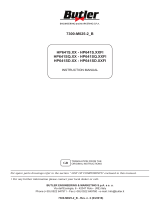
Clamp the rim
Of the 17.5 ", 19.5" , 22.5 "rims, which have different
clamping methods and positions depending on the type of
rims. Refer to FIG.
Adjust the main shaft angle, and operate the joystick to
clamp the rim. Operate the main shaft control joystick to
lift it to a height convenient for operation of the tire
changing.
FIG.07
Tire dismounting and remounting.
Use bead press roller to break the bead.
To make sure the rim is clamped and deflate the air.
During the operation, to adjust to open the jaws.
Operate the joystick to place the bead press roller
close to the edge of the tire bead.
FIG.08 FIG.09
Rotate the wheel, and meanwhile operate on the
bead press roller to move upwards or downwards.
Continue to do the bead breaking until the bead has
been completely opened in order to apply the tire
lubricant to avoid the damage on rim and tire during
the operation.
Be very careful! Do not place your fingers between the tire
and the tool. To prevent any possible danger, turn
counterclockwise while operating the inner and outer edges.
6. Remove the bead press roller from the rim edge, release
the tool holder lock, lift the support arm out of work condition,
and move the bead press roller to the inside.
FIG.10
Tire dismounting
1 Tilt the tire at about 45 place the bead press roller
straightT o use different tire lifting stages according to truck
wheel width
4
FIG.11
2Slo wly adjust the tire demounting tool head into the back
of the tire bead. After the main shaft is adjusted to be
horizontal, lift the tire demounting hook and the bead press
roller.
FIG.12
3W hen the tire bead is about 5cm above the rim, turn the
wheel counterclockwise so that the first bead is removed from
the rim.
4C ontinue to raise the tire demounting hook upward so that
the second bead is completely off the rim
(Note: hold the tire well when the tire falls off completely to
avoid slipping off)
5 Turn the main shaft so that the tire touches the ground to
repair the tire and other following work.
Tire remounting
1 After the following work is completed, use the rim to
contact the tire bead, and the spindle is turned to the
horizontal position to prepare for the remounting of the tire.
2Use the bead press roller to mount the first bead of the tire.
FIG.13
3 Lower down the bead press roller continuously to complete
the remounting of the second bead. When remounting, If the
second bead comes out of the rim, use a tire press assistant to
install the tire.
FIG.14
4R aise the bead press roller, turn the spindle over, the tire
touches the ground, loosen the jaws, take off the tire, and tire
remounting is completed.
Be very careful! Do not place your fingers between the tire
and the tool while operating to avoid any possible hazards.
When the tire comes off the rim, the tire will fall off.
So make sure that the irrelevant people are not in the
workplace.
5
Maintenance
Regular maintenance according to the manual is the basis of
correct use of the tire changer, and can extend its working life,
to ensure the reliability of the machine operation.
To ensure safety, disconnect the plug before performing
repairs and maintenance.
To use the original parts, and ask the professional person to
replace the defective parts.
Clean the following parts carefully regularly with diesel oil
and fill with grease.
(1) trailer guide, (2) tool bracket horizontal axis, (3) lifting
cylinder.
The hydraulic system USES HV type 32# hydraulic oil in
winter and HV type 46# hydraulic oil in summer.
For the new machine after running 200 - 300 hours or when
the valve is seriously jammed, please replace the hydraulic oil,
after the use of 800 hours, check once a week hydraulic pump
hydraulic oil within the tank and oil: such as oil amount is
insufficient, please add HV 32 # hydraulic oil or HV 46 #
hydraulic oil, such as black oily or deterioration, replace the
hydraulic oil.The worm gears are cleaned regularly (quarterly)
with diesel oil and smeared with lithium-based grease.
Safekeeping: if not used for a long time (3~4 months), keep it
properly;
Lower the lifting arm.
make the lifting arm free of load
Unplug the power.
The trailer guide rail is greased.
Empty the fuel tank.
To grease tool support vertical shaft grease.
Transportation, Package, Storage
The machine must be transported in the original packing box
and placed according to the position shown in the packing box.
The forklift truck should be capable to handle the machine.
The location of the fork is shown in FIG.26
After unpacking and removing the package, it is necessary to
ensure that the tire changer is intact in the transportation
process, take out the standard accessories, packaging and
properly handle; Take care not to bruise the control console
during this period. If the machine is temporarily stored, make
sure that the storage environment is as follows: maximum
relative humidity: 95%, temperature: minimum -5 C,
maximum +40 C.
6
Hydraulic Principle Diagram
Technical parameters
1. Motor: 3KW/380V/220V;
1400 r/m in three phase.
2. Oil pump: displacement;
3.1 ML/r;
Rated working pressure: 15MPa.
3. Separate design of motor oil pump and valve plate.
7
Electrical Principle Diagram
It is absolutely forbidden to inflate the tire on the tire change
The manufacturer reserves the right to make changes
to the products without prior notice to the Buyer.
20220128L
  • Page 1 1
  • Page 2 2
  • Page 3 3
  • Page 4 4
  • Page 5 5
  • Page 6 6
  • Page 7 7
  • Page 8 8
  • Page 9 9

Toolots BP585 User manual

Type
User manual

Toolots BP585 is a versatile tire changer designed for efficient and safe tire mounting, demounting, and servicing of truck tires. With a maximum wheel weight capacity of 1000Kg and a maximum wheel diameter of 1300mm, it can handle a wide range of truck tire sizes, including 17.5", 19.5", and 22.5". The hydraulic motor, with a torque of 640Nm, provides ample power for effortless tire handling. The user-friendly operation console allows for precise control of the main shaft, jaws, and bead press roller, ensuring smooth and accurate tire changes.

Ask a question and I''ll find the answer in the document

Finding information in a document is now easier with AI