Scientific SM5071 Owner's manual
- Category
- Measuring, testing & control
- Type
- Owner's manual

UserManual
3MHzFunctionGenerator/
Counter
S 5070/SM5071M

ScientificMes-TechnikPvt.Ltd.,
B-14IndustrialEstate,Pologround,
Indore452015(India)
Tel:0731-2422330/31/32/33
Fax:0731-2422334,561641
Email:[email protected]
Copyright©Scientific Allrightsreserved.
This instrument contains proprietary information, no part of this manual may
be photocopied, reproduced or translated without any prior written consent.
Information in this manual supercede all corresponding previous released
material.
Scientific continues to improve products and reserves rights to amend part
or all of the specifications, procedures, equipment at any time without
notice.
Rev2.2/0312
2
SM 070/SM5071U5 serManual

3MHzFunctionGenerator/Counter
S 5070/SM5071
TableofContents
M
1. Introduction........…………………….………..….. 4
2. TechnicalSpecifications.............….……...…..... 5
3. FrontPaneldiagramSM5070……….................. 7
Front Panel diagram SM5071 ............................. 8
Front Panel Controls........................................... 9
4. Rear Panel Controls…………………………..….. 11
5. OperatingInstructions…............………………… 12
General Information…..……………………... 12
Safety….........……………………...………… 12
OperatingConditions …...…………………… 12
First TimeOperation…..……………………… 13
FunctionSelection….......…………………….13
Frequency Adjustment…................….……… 13
OutputAmplitude & Signal Connection…........ 13
Trigger Output…...........……………………... 14
Sweep Facilities….....……………………….. 14
Internal Sweep…...……………………… 14
FMInput…....……………………………....14
DC Offset ….......………………………………. 15
Frequency counter(SM5071)........................ 15
6. Maintenance ………………………………..….…. 17
PowerLineFuseReplacement …………… 17
7. Dispatch Procedure for
Service………………………………..………… 18
8. WarrantyConditions....……………..........…...… 19
9. ListofServiceCenters....…………….................. 20
3
SM5070/SM5071UserManual
0312/Ver2.2

FrequencyRange0.3Hzto3MHz
OperatingModes:Sine,Square,Triangle,DC
DigitalFrequencyReadout
DC-Offset Adjustment
InternalSweepFacilities
SquareWaveRisetimeTyp.40ns
BacklitLCDdisplayformodes&frequency
CounterSensitivity50mVrms(SM5071)
Counter Range 10 Hz - 15 MHz ( SM5071)
SM5070/SM5071
16*2 dot matrix LCD display
low
distortion factor constant amplitude flatness
SM5070/SM5071
SM5070/SM5071 sweep mode
3MHzFunctionGenerator/Counter
S070/SM5071M5
■
■
■
■
■
■
■
■
■
The various signals available from the Function Generator
makes it a versatile signal source useful for most measurement and test
applications. Its low frequency ranges are particularly well suited for simulating
mechanical and servo techniques.
Frequencies are read out on a with a maximum
resolution of 1 mHz. Additional quality features include the relatively
of the generated signals and
throughout the entire frequency range of the instrument. All outputs are short-
circuit-proof in .
The can also be used in the with an internal or
external signal source.
4SM 070/SM5071U5 serManual

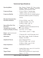
TechnicalSpecifications
Operating Modes , , ,
FrequencyRange :
FrequencyStability :
Waveform Characteristics
SineWaveDistortion :
SquareWaveRiseTime :
Overshoot :
TriangularNon-Linearity :
FrequencyDisplay Accuracy:
Output
Outputvoltage :
Attenuation :
AmplitudeFlatness :
OutputImpedance :
DC Offset :
TriggerOutput : ,
: Sine Square Triangle DC, Free running,
internal sweep or external frequency
modulation, with or without DC offset
0.3Hzto3MHzin7decadesteps,
variablecontrol:x0.1tox1(10:1)
<0.5%/hor0.8%/24hatconstantambient
temperature(Mediumpositionoffrequency
Control)
0.3Hzto100kHz:max.0.5%
0.1MHzto0.5MHz:max.1.5%
0.5MHzto3MHz:max.3%
Typ. 40ns(10to90%)
5%(whenoutputisterminatedwith50 )
<1%(upto100kHz)
upto3Hz:±(1%+3digit)
3Hzto3MHz:±(5x10 +1Digit)
(shortcircuitproof)
10Vppinto50 ,max20Vppopencircuit
Max.60dB,2steps:20dB±0.2dBeach
Variable:0to20dB
(sine/triangleinto50 )
0.3Hzto0.3MHz:max.±0.2dB
0.3MHzto3MHz: max.±0.5dB
Switchable50 /600
Variable Offset range : max.± 2.5 V into 50 ,
max. ± 5 V open circuit
Squarewavesynchronoustosignaloutput
Approx.+5V(TTL)
<
<W
W
W
W W
W
-5
5
SM5070/SM5071UserManual

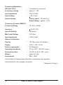
FrequencyModulation:
FMinput(VCF) :
Frequencychange :
InputImpedance :
InputVoltage :
InternalSweep : Sweepspeed:
SweepRange:
FrequencyCounter(SM5071):
FrequencyRange :
Accuracy :
InputSensitivity
Max.InputVoltage
InputImpedance
Generalinformation
Display :
Supply :
Powerconsumption :
OperatingConditions :
Dimensions(mm) :
Weight :
Accessories :
Connectoronrearpanel
Approx.1:100
50k ||25pF
30Vmax.
20msto4s
approx.1:100.
10Hzto15MHz
(5x10 +1D)
:50mVrms
:150Vrms
:1M ||50pF
16*2dotmatrixLCDdisplay
230V, 10%,50Hz
22VA approx
0 Cto+50 C.,RH95%(max.)
W:205,H:95,D:292(mm)
Approx2.0kg.
BNC – BNC
Valueswithouttolerancesareintendedasguidelinesandrepresent
characteristicsoftheaverageinstrument.
(SubjecttoChange)
W
W
±
+
+-5
0 0
6SM 070/SM5071U5 serManual

7
SM5070/SM5071UserManual
3MHzFUNCTIONGENERATOR
COUNTER 5070SM
33
4
2
14 15
13
12
6
5
8
7
10
11
9
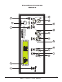
FrontPanelControls
S 5070M

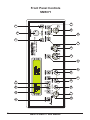
FrontPanelControls
SM5071
8SM 070/SM5071U5 serManual
3MHzFUNCTIONGENERATOR
COUNTERSM5071
33
4
2
15
13
12
6
5
7
10
11
9
14
8
20
17
19
18
16
EXTIN
FC
LEVEL
TRIG 1:10

POWER
DIGITAL DISPLAY
Range :
FREQUENCY :
OFFSET :
AMPLITUDE :
FUNCTION :
SPEED :
SWEEP :
WIDTH :
OFFSET :
50 /600 :
-20 dB :
OUTPUT (BNC connector) :
-20 dB :
FC (Push button) :
EXT IN (BNC CONNECTOR) :
:Pushbuttonswitchforsupplyingpowertoinstrument.
: 16*2 dot matrix LCD display
Frequency range selection from 0.3 Hz to 3 MHz in 7decade steps
(adjusting knob) Continuous and linear frequency fine
adjustment, overlapping the ranges selected with . Setting range from x0.09
to x 1.1 of the selected range.
Adjustment of the positive or negative offset voltage. DC voltage
can be superimposed on the output signal. The max. offset voltage is ± 5 V
(o.c.) or ± 2.5 V when terminated with 50
Continuous adjustment of the output amplitude from 0 to – 20
dB .
Mode selection switch (Triangle- Sine – Square – DC)
Setting of wobbulation speed in Sweep mode
Activates the internal Sweep mode
Setting of wobbulation width
Activates the DC offset function
When pressed the output signal gets attenuated by 20 dB fixed
attenuator.
Short-circuit-proof signal output of the generator.
The output impedance is 50 /600 , and the max. output amplitude is 20 V
(o.c.) or 10 V respectively when terminated with 50
When pressed the output signal gets attenuated by 20 dB fixed
attenuator. When both attenuator push buttons are activated, a total
attenuation of 40dB results. Including the amplitude control the max.
attenuation amounts to 60 dB (factor 1000).
When pressed instrument reads frequency of the input
connected on “EXT-IN”BNC connector.
Input to frequency counter. (max 15 MHz)
W.
W W
W W
W
Selects the output impedance at the output BNC
pp
pp
9
SM5070/SM5071UserManual
4
1
2
3
5
6
7
8
9
10
11
12
13
14
15
16
17
3

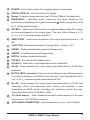
Trigger level setting of counter.
When pressed the trigger level of counter can be
adjusted with help of LEVEL potentiometer.
When pressed the input signal to frequency counter is
attenuated 10 times.
LEVEL (adjusting knob):
TRIG (Push button) :
1:10 (push button):
10 SM 070/SM5071U5 serManual
18
19
20

TTL- OUT (Banana socket) :
FM-IN(Bananasocket):
Mains:
SpareFuse:
Trigger output BNC.
ExternalinputforFM.
Mainsinput230V AC50Hz 10%.
Sparefuseformainsiskeptinside.
+
11
SM5070/SM5071UserManual
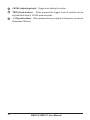
Rear Panel Controls
21
24
22
23
SCIENTIFICMESTECHNIK
PVT.LTD.
B-14POLOGROUND
INDUSTRIAL ESTATE
INDORE452015INDIA
SM5070/SM5071
Power:230V,50Hz
Watts:22VA(approx.)
Fuse:0.15A,timelag,5x20mm
2423
TTL-OUT
FM-IN
Sr.No.XXXXXXXX
21 22
GND

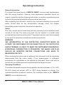
Operating Instruction
General Information
Safety
WARNING!
ANY INTERRUPTION OF THE PROTECTIVE CONDUCTOR INSIDE OR
OUTSIDE THE INSTRUMENT OR DISCONNECTION OF THE PROTECTIVE
EARTH TERMINAL IS LIKELY TO MAKE THE INSTRUMENT DANGEROUS.
INTENTIONAL INTERRUPTION IS PROHIBITED. THE MAINS/ LINE PLUG
SHOULD BE INSERTED BEFORE CONNECTIONS ARE MADE TO
MEASURING CIRCUITS
Operating Conditions
S 5070/
SM5071
The logical front panel layout of ensures rapid familiarization
with the various functions. However, even experienced operators should not
neglect to carefully read the following instructions, to avoid any operational errors
and to be fully acquainted with the instrument when later in use.
After unpacking the instrument, check for any mechanical damage or loose parts
inside. Should there be any transportation damage, inform the supplier
immediately and do not put the instrument into operation.
The case, chassis and all measuring parts are connected to the protective earth
contact of the inlet. The mains plug shall only be inserted in a socket outlet
provided with a protective earth contact. The protective action must not be negated
by the use of an extension cord without a protective conductor.
.
When removing the metal case or replacing, the instrument must be completely
disconnected from the mains supply. If any measurement or calibration
procedures are unavoidable on the opened-up instrument, these must only be
carried out by qualified personnel acquainted with the danger involved.
The ambient temperature range during operation should be between + 0 to + 50 C
RH 95% should not exceed -40 C or +70 C during transport or storage. The
operational position is optional, however, the ventilation holes on the
must not be obstructed.
SM5070/ SM5071
M
0 0
0 0
12 SM 070/SM5071U5 serManual

First Time Operation
Function Selection
S 5070/
SM5071
Frequency Adjustment
Output Amplitude and Signal Connections
After unpacking the instrument check for any mechanical damages. The
instrument should be plugged in mains-plug of proper mains supply 230V 10%.
On switch ON no undue observation should be noticed. Once the instrument is
switched ON, the power ON is indicated by liting of displays.
The type of output signal is selected with the function selection switch . A total
number of 4 different waveforms - sine, square, triangle are available apart from the
DC level. The functions are marked with the corresponding symbols. If the
"OFFSET” pushbutton is activated a DC voltage level is supplied by the
is superimposed on the output signal.
Coarse adjustment is performed with the range keys. The desired frequency is
selected by turning the FREQUENCY control .
The selected frequency appears on the LCD display. Compared to knob scales,
this display has a much higher resolution and accuracy.
Adaptation in decade steps to the desired amplitude range is performed by the use
of two attenuators with -20 dB each, which are activated by push buttons &
Including the continuously adjustable AMPLITUDE control the maximum
attenuation amounts to –60 dB. With the maximum amplitude of 10V , the
minimum signal voltage to be supplied is about 10 mV. These values are obtained
when the generator output is terminated with 50 . In the open-circuit condition, the
available signal amplitude is twice as high. Therefore the maximum output voltage
of the output socket is specified with 20 V .
If exact square-shaped signals are required, care should be taken that only 50
coaxial cables are used. Furthermore, this cable must be terminated with a 50
through termination. If these precautions are not observed, overshoot may occur,
especially when high frequencies are selected. If test circuits having a 50 input
impedance are connected, this termination is not required.
+
M
pp
pp
W
W
W
W
13
SM5070/SM5071UserManual
4

In high signal voltage ranges it should be noted that the used terminating resistor
must dissipate the corresponding effective power.
The output terminal of the is short circuit proof. If the output of
the unit comes into contact with components of the circuit under
test, which are carrying DC voltage, an isolating capacitor of appropriate dielectric
strength should be connected in series with the output of the generator. The
capacitance of this isolating capacitor should be selected in such way that the
frequency response of the output signal is not affected over the whole frequency
range of the unit.
In the sine, square and triangle modes, the trigger output (at back panel) supplies a
square signal in synchronism with the output signal. Set up time is considerably
reduced because the fixed logic levels and polarity are ready for direct injection
into any TTL circuits. An offset voltage adjusted at the 50 output has no influence
upon the trigger signal. The trigger output is short-circuit proof and can drive
several TTL inputs.
The internal sweep facility of the allows checking of filters and
equipment in the frequency range from 0.3 Hz to 3 MHz. Operation is very easy
and is confined to the setting of sweep-speed and sweep-width. Activation is by
simply pressing the push button and can be combined with all available
functions on the The Stop- frequency is automatically given by
the settings of the range selector and the frequency dial and is shown on the LCD
display. Start frequency is related to the stop-frequency by the sweep-width factor.
Latter is set by means of the (Sweep) Width potentiometer and is up to approx. X
l00.The sweep speed is set by means of the (Sweep) Speed potentiometer and
ranges from 20 ms to 4 s. For external wobbulation please refer to "FM input".
If a positive DC voltage is applied to the FM input on the rear BNC of
, the generator frequency increases and is accordingly displayed. A
negative DC voltage reduces the frequency. The frequency displacement depends
S 5070/ SM5071
SM5070/SM5071
SM5070/SM5071
Trigger Output
Sweep Facilities
Internal Sweep
S 5070/ SM5071
SWEEP
S 5070/ SM5071.
FM input
S 5070/
5071
M
M
M
M
SM
W
14 SM 070/SM5071U5 serManual

on the value and polarity of the DC voltage U and on the FREQUENCY setting.The
set frequency N (DC voltage not included) can be selected at will.
: N = N +A.U or U = (N-N )/A
N = digit display without voltage U,
N = digit display including voltage U,
U = ± voltage at the FM input ,
A = 740 (digits per volt)
It should be noted that only the displayed digits are valid; the decimal point is not
taken into consideration (e.g. 100.0 1000 digit). The max. frequency (3 MHz)
cannot and "000" should not be exceeded. Any zeros preceding the decimal point
are dropped.
If the highest displayed number is N = 3000 and the smallest N = 300, then
U will be +3.6 V max. The frequency increases by a factor of 10.If the smallest
displayed number is N = 30 (lower number are possible, but inaccurate) and the
highest N = 3000, then will be 4 V max.
The frequency changes by a factor of 100.The frequency change is linear as a
function of the voltage and has the same value in all ranges.
This mode can be used in applications where the periodically required frequencies
are to be set , This will eliminate the repetitive setting of frequency from front panel
via FREQUENCY set knob. Such applications exists in production departments,
where signals at several specific frequencies are required for various tests. FSK
(Frequency Shift Keying) signals also may be generated in this manner.
When the switch OFFSET is depressed, a DC voltage can be superimposed on
the output signal. The maximum offset voltage with open output is ± 5 V. If large DC
offset is added or a large signal is added with DC offset, make sure that the desired
combination is obtained without clipping. An oscilloscope may be used for proper
setting of DC offset addition.
Input signal to the counter is given to EXT IN BNC terminal.
The minimum applied signal is 50 mVrms and maximum applicable signal is 150
Vrms.
o
o o
o
o
o
Computation
Limits :
U -
U
DC Offset
1. INPUT SIGNAL :
Frequency Counter: (SM5071)
15
SM5070/SM5071UserManual
11
17

2. TRIGGER :
3. ATTENUATOR:
4. FUNCTION GENERATOR / COUNTER MODE:
In normal mode counter is auto triggered. When TRIG switch
is pressed, instrument can be triggered externally by adjusting LEVEL
Knob .When instrument is triggered trigger LED is ON.
The input signal to frequency counter can be attenuated 10
times by pressing 1:10 Switch.
When switched ON the
instrument works as a function generator. By pressing FC Switch the
instrument function as a Frequency Counter.
16 SM 070/SM5071U5 serManual
20
9
18
10

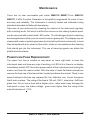
Maintenance
There are no user serviceable part inside .Your
3 MHz Function Generator is thoughtfully engineered for ease of use,
accuracy and reliability. The instrument is carefully tested and calibrated using
standards traceable to National Laboratories.
Take care of your instrument by cleaning the exterior of the instrument regularly
with a dusting brush. Dirt which is difficult to remove on the casing & plastic parts,
can be removed with a moist cloth ( 99% water, 1% mild detergent) spirit or washing
benzene(petroleum ether) can be used to remove greasy dirt. The display may be
cleaned with water or washing benzene (but not with spirit-alcohol solvents), it must
then be wiped with a dry clean lint-free cloth. Under no circumstances the cleaning
fluid should get into the instrument. The use of cleaning agents can attack the
plastic & paint surfaces.
The power line fuse is located on rear panel on lower right side. In case, the
instrument does not show any sign of working, no LED is lit or there is no display
immediately switch OFF the mains power switch of the instrument and unplug the
mains cord from the mains socket. With the help of small flat blade screwdriver
remove the fuse cap of the fuse holder, located just below the socket. There is one
spare fuse kept in the fuse cap, replace it for the defective one. Press the cap so
that it locks in place . The rating of the fuse is 150 mA , 250 V , slow blow , 5x20 mm
glass fuse. Do not use a fuse with a higher value other wise it may damage the
instrument in case, the mains voltage goes much higher than the rating of the
mains fluctuation of 10%.
S 5070/ SM5071 S 5070/
S 5071
M M
M
Power Line Fuse Replacement
+
17
SM5070/SM5071UserManual

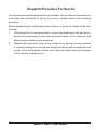
Dispatch Procedure For Service
No user serviceable parts are inside the instrument, should it become necessary to
send back the instrument to factory for service, please observe the following
procedure.
Before dispatching the instrument please write to us giving full details of the fault
noticed.
1. After receipt of your communication, our service department. will advise you
whether it is necessary to send the instrument back to us for repairs or the
adjustment is possible in your premises.
2.Dispatchtheinstrument(onlyonthereceiptofouradvise)securelypacked
inoriginalpackingdulyinsuredandfreightpaidalongwithaccessoriesand
acopyofthefaultsdetailsnoticedatourServiceCenterlistedonlastpage
ofthismanual,nearesttoyou.
18 SM 070/SM5071U5 serManual

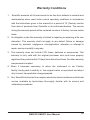
Warranty Conditions
1. Scientific warrants all its Instruments to be free from defects in material and
workmanship when used under normal operating conditions in accordance
with the instructions given in the manual for a period of 12 (Twelve) months
from date of purchase from Scientific or its authorised dealers. The service
during the warranty period will be rendered on return to factory /service center
basis.
2. Its obligation under this warranty is limited to repairing or replacing at its own
discretion. This warranty shall not apply to any defect, failure or damage
caused by accident, negligence, mis-application, alteration or attempt to
repair, service or modify in any way.
3. This warranty does not include LCD, fuses, batteries or accessories. This
warranty is only valid with the original purchaser who must have properly
registered the product within 15 days from date of purchase. No other warranty
is expressed or implied.
4. When it becomes necessary to return the instrument to our Factory
facility, kindly pack it carefully in the original carton or equivalent and ship it
duly insured, transportation charges prepaid.
5. Your Scientific instrument is a complex electronic device and deserves the best
service available by technicians thoroughly familiar with its service and
calibration procedures.
19
SM5070/SM5071UserManual
-
 1
1
-
 2
2
-
 3
3
-
 4
4
-
 5
5
-
 6
6
-
 7
7
-
 8
8
-
 9
9
-
 10
10
-
 11
11
-
 12
12
-
 13
13
-
 14
14
-
 15
15
-
 16
16
-
 17
17
-
 18
18
-
 19
19


Scientific SM5071 Owner's manual
- Category
- Measuring, testing & control
- Type
- Owner's manual
Ask a question and I''ll find the answer in the document
Finding information in a document is now easier with AI
Related papers


Other documents
-
SEFRAM BK 4052-3-4-5 User manual
-
SRS DS335 Owner's manual
-
-
-
GW Instek GFG-3015 User manual
-
-
-
Tektronix AFG3022 User manual
-
Tektronix AFG2021 Owner's manual
-
Wavetek 29 10 MHz DDS Function Generator Owner's manual