Page is loading ...

ICA
™
SERIES
INDUSTRIAL CONTRACTOR AMPLIFIERS
OPERATING GUIDE

2
Intended to alert the user to the presence of uninsulated “dangerous voltage” within the product’s
enclosure that may be of sufficient magnitude to constitute a risk of electric shock to persons.
Intended to alert the user of the presence of important operating and maintenance (servicing)
instructions in the literature accompanying the product.
CAUTION: Risk of electrical shock — DO NOT OPEN!
CAUTION: To reduce the risk of electric shock, do not remove cover. No user serviceable parts inside. Refer
servicing to qualified service personnel.
WARNING: To prevent electrical shock or fire hazard, do not expose this appliance to rain or moisture. Before
using this appliance, read the operating guide for further warnings.
Este símbolo tiene el propósito, de alertar al usuario de la presencia de “(voltaje) peligroso” sin ais-
lamiento dentro de la caja del producto y que puede tener una magnitud suficiente como para constituir
riesgo de descarga eléctrica.
Este símbolo tiene el propósito de alertar al usario de la presencia de instruccones importantes sobre la
operación y mantenimiento en la información que viene con el producto.
PRECAUCION: Riesgo de descarga eléctrica ¡NO ABRIR!
PRECAUCION: Para disminuír el riesgo de descarga eléctrica, no abra la cubierta. No hay piezas útiles dentro.
Deje todo mantenimiento en manos del personal técnico cualificado.
ADVERTENCIA: Para evitar descargas eléctricas o peligro de incendio, no deje expuesto a la lluvia o humedad
este aparato Antes de usar este aparato, Iea más advertencias en la guía de operación.
Ce symbole est utilisé dans ce manuel pour indiquer à l’utilisateur la présence d’une tension dangereuse
pouvant être d’amplitude suffisante pour constituer un risque de choc électrique.
Ce symbole est utilisé dans ce manuel pour indiquer à l’utilisateur qu’il ou qu’elle trouvera d’importantes
instructions concernant l’utilisation et l’entretien de l’appareil dans le paragraphe signalé.
ATTENTION: Risques de choc électrique — NE PAS OUVRIR!
ATTENTION: Afin de réduire le risque de choc électrique, ne pas enlever le couvercle. Il ne se trouve à l’intérieur
aucune pièce pouvant être reparée par l’utilisateur. Confiez I’entretien et la réparation de l’appareil à un réparateur
Peavey agréé.
AVERTISSEMENT: Afin de prévenir les risques de décharge électrique ou de feu, n’exposez pas cet appareil à la
pluie ou à l’humidité. Avant d’utiliser cet appareil, lisez attentivement les avertissements supplémentaires de ce
manuel.
Dieses Symbol soll den Anwender vor unisolierten gefährlichen Spannungen innerhalb des Gehäuses
warnen, die von Ausreichender Stärke sind, um einen elektrischen Schlag verursachen zu können.
Dieses Symbol soll den Benutzer auf wichtige Instruktionen in der Bedienungsanleitung aufmerksam
machen, die Handhabung und Wartung des Produkts betreffen.
VORSICHT: Risiko — Elektrischer Schlag! Nicht öffnen!
VORSICHT: Um das Risiko eines elektrischen Schlages zu vermeiden, nicht die Abdeckung enfernen. Es befinden
sich keine Teile darin, die vom Anwender repariert werden könnten. Reparaturen nur von qualifiziertem
Fachpersonal durchführen lassen.
ACHTUNG: Um einen elektrischen Schlag oder Feuergefahr zu vermeiden, sollte dieses Gerät nicht dem Regen
oder Feuchtigkeit ausgesetzt werden. Vor Inbetriebnahme unbedingt die Bedienungsanleitung lesen.

TABLE OF CONTENTS
Page
INTRODUCTION . . . . . . . . . . . . . . . . . . . . . . . . . . . . . . . . . . . . . . . . . . . . . . . . . . . . 4
UNPACKING . . . . . . . . . . . . . . . . . . . . . . . . . . . . . . . . . . . . . . . . . . . . . . . . . . . . . . . 4
INSTALLATION AND MOUNTING . . . . . . . . . . . . . . . . . . . . . . . . . . . . . . . . . . . . . . . 4
BASIC SETUP. . . . . . . . . . . . . . . . . . . . . . . . . . . . . . . . . . . . . . . . . . . . . . . . . . . . . . 4
FRONT PANEL FEATURES. . . . . . . . . . . . . . . . . . . . . . . . . . . . . . . . . . . . . . . . . . . . 5
BACK PANEL FEATURES . . . . . . . . . . . . . . . . . . . . . . . . . . . . . . . . . . . . . . . . . . . . . 6
OPERATION . . . . . . . . . . . . . . . . . . . . . . . . . . . . . . . . . . . . . . . . . . . . . . . . . . . . . . . 7
PROTECTION FEATURES . . . . . . . . . . . . . . . . . . . . . . . . . . . . . . . . . . . . . . . . . . . . 9
SEQUENTIAL TURN-ON / TURN-OFF. . . . . . . . . . . . . . . . . . . . . . . . . . . . . . . . . . . . 10
WIRE GAUGE CHART . . . . . . . . . . . . . . . . . . . . . . . . . . . . . . . . . . . . . . . . . . . . . . . 11
ICA
™
600 SPECIFICATIONS . . . . . . . . . . . . . . . . . . . . . . . . . . . . . . . . . . . . . . . . . . . 12
ICA
™
1200 SPECIFICATIONS . . . . . . . . . . . . . . . . . . . . . . . . . . . . . . . . . . . . . . . . . . 13
ICA
™
2400 SPECIFICATIONS . . . . . . . . . . . . . . . . . . . . . . . . . . . . . . . . . . . . . . . . . . 14
ICA
™
400V SPECIFICATIONS . . . . . . . . . . . . . . . . . . . . . . . . . . . . . . . . . . . . . . . . . . 15
ICA
™
800V SPECIFICATIONS . . . . . . . . . . . . . . . . . . . . . . . . . . . . . . . . . . . . . . . . . . 16
ICA
™
2400V SPECIFICATIONS . . . . . . . . . . . . . . . . . . . . . . . . . . . . . . . . . . . . . . . . . 17
IMPORTANT SAFETY INSTRUCTIONS. . . . . . . . . . . . . . . . . . . . . . . . . . . . . . . . . . . 18
WARRANTY INFORMATION . . . . . . . . . . . . . . . . . . . . . . . . . . . . . . . . . . . . . . . . . . . 19
3

INTRODUCTION
Congratulations on your purchase of an Architectural Acoustics ICA
™
(Industrial Contractor Amplifier)
from Peavey Electronics. Please read this manual carefully, especially the IMPORTANT SAFETY
INSTRUCTIONS on page 18. It contains information vital to safe operation of the power amplifier.
Also, please fill out and return the enclosed product registration card.
ICA Series amplifiers represent new levels of value and flexibility never before offered to the
contracting market. The ICA Series features models specifically designed to drive 4-ohm outputs,
70.7-volt outputs, and 100-volt outputs. 70.7 and 100-volt outputs can be driven directly, eliminating
the need for transformers or autoformers. These amplifiers cover almost every installed or
distributed sound power requirement imaginable.
ICA Series amplifiers are ruggedly built from high-quality components and feature comprehensive
protection circuits to protect your amplifier from those “real world” occurrences.
If you need setup or operational assistance for this product, please call the Peavey Electronics
Customer Service Department or your local Peavey Electronics representative. We appreciate
suggestions that may help us improve our products and/or service.
UNPACKING
Inspect the amplifier during unpacking. If you find any damage, notify your dealer immediately.
Only the consignee may institute a claim with the carrier for damage incurred during shipping. Be
sure to save the carton and all packing materials. Should you ever need to ship the unit back to
Peavey Electronics, one of its service centers, or the dealer; use only the original factory packing.
INSTALLATION AND MOUNTING
ICA Series amplifiers are 2 or 3-rack-space units of 15 3/4" (400 mm) depth that mount in a
standard 19" rack. On all amplifiers, front panel mounting holes are provided.
BASIC SETUP
1. Rack mount the amplifier in the location where it is to be used, remembering to allow for
adequate access and cooling space. For more information, see the sections on
INSTALLATION AND MOUNTING and COOLING REQUIREMENTS.
2. Make input connections to the plugable terminal blocks on the rear panel. Use the proper
connections for stereo, parallel, bridged mono, and grounding configuration. See the sections
on SIGNAL MODE CONFIGURATION and INPUT MODULE CONNECTIONS for more
information.
3. Connect speakers to the output barrier strip. Be sure to make the correct output connections
for stereo, parallel or bridged mono configuration. See the section on SPEAKER OUTPUT
CONNECTIONS for more information.
4. Make power connections, allowing for proper current draw. See the sections on IEC POWER
CONNECTOR and AC MAINS CIRCUIT SIZE REQUIREMENTS for more information.
5. Turn the front panel 3-position AC POWER switch to ON and bring up the back panel LEVEL
(gain) attenuators to the desired levels.
4
ENGLISH

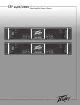
FRONT PANEL FEATURES
1. RACK MOUNTING EARS
These mounting holes are provided on each front mounting ear.
2. 3-POSITION AC POWER SWITCH
A 3-position switch is on the front panel. Sequential remote turn-on capability is a standard
feature. With the switch pushed towards the outside position, the amplifier is ON. The middle
position is OFF, and the inside position is marked STANDBY. When switched to STANDBY,
the amplifier may be activated by the sequential turn-on circuit. See the section on
SEQUENTIAL TURN-ON / TURN-OFF for more information.
3. POWER LED
The POWER LED illuminates when the amplifier is turned on.
4. SIGNAL LED
Each channel has a SIGNAL LED that illuminates when the amplifier output exceeds 1 volt.
5. CLIP LED
Each channel has a CLIP LED that illuminates at the clipping point, and indicates that internal
circuitry is reducing amplifier gain to allow full power. See the section on PROTECTION
FEATURES for more information.
6. LFC
™
LED
Each channel has a LFC (Load Fault Correction) LED. This LED illuminates when the
amplifier channel detects an abnormal load condition. Internal circuitry will instantaneously
reduce the channel gain to allow the amplifier to operate at a safe level into the abnormal
load. See the section on PROTECTION FEATURES for more information.
7. PROTECT LED
If the amplifier has just been turned on or has detected a fault condition, the speaker output
relays will open, illuminating this LED.
5
RCHITECTURAL
COUSTICS
POWER
STANDBY
OFF ON
TM
PROTECT
LFCCLIPSIGNAL
A
B
POWER
by
TM
INDUSTRIAL
CONTRACTOR
AMPLIFIER
600
TM
4
5
6 7 3
2
1

BACK PANEL FEATURES
8. INPUT SECTION
The ICA
™
Series comes standard with plugable input connectors and individual channel rotary
attenuators. Connections at the input connector permit the audio signal ground to be
connected or lifted from the chassis ground.
9. OUTPUT BARRIER STRIP
A barrier strip is provided for connection of loudspeakers with bare wire or spade lug
connectors. This barrier strip can accommodate up to two 10-gauge wires per terminal.
10. IEC POWER CONNECTOR
A standard IEC power connector is located at the upper left corner of the amplifier rear panel.
An AC mains cord having an appropriate AC plug for the intended operating voltage is
included.
NOTE: FOR UK ONLY
If the colors of the wires in the mains lead of this unit do not correspond with the colored
markings identifying the terminals in your plug, proceed as follows: (1) The wire that is
colored green and yellow must be connected to the terminal that is marked by the letter E,
the earth symbol, colored green, or colored green and yellow. (2) The wire that is colored
blue must be connected to the terminal that is marked with the letter N or the color black. (3).
The wire that is colored brown must be connected to the terminal that is marked with the
letter L or the color red.
11. CIRCUIT BREAKER
A resettable, protective AC circuit breaker is located at the upper left of the amplifier back
panel. If the breaker has tripped, push it back in to return the amplifier to operating condition.
If the breaker continues to trip, the amplifier needs servicing. Do not continue to reset the
breaker because severe internal damage and safety hazards could occur!
12. SEQUENTIAL TURN-ON CONNECTOR
The ICA
™
Series comes standard with remote-controllable sequential turn on enabled by
setting the front power switch to STANDBY. The amplifier is activated by applying a voltage
between 12 to 24 volts DC to the rear-mounted, 4-pin plugable terminal, and connecting the
ENABLE terminal to the 24 V DC+ terminal. When no voltage is present or the ENABLE
connection is opened, the amplifier will switch off. Other ICA Series amplifiers can be “daisy
chained” by connecting all 24 V DC+ terminals together, all COMMON terminals together, and
6
1110
9
12
13 8

connecting the ENABLE OUT to the ENABLE IN of the next amplifier. A mating connector is
shipped with the amplifier.
13. FAN GRILL
A continuously variable-speed DC fan supplies cool air into the amplifier. Do not block this
intake! The fan operates only when the amplifier heat sinks require cooling.
OPERATION
AC MAINS CIRCUIT SIZE REQUIREMENTS
Power requirements for ICA
™
amplifiers are rated at “idle”, 1/8 power (“typical” music
conditions), 1/3 power, and maximum rated power. The maximum power current draw rating
is limited by the amplifier’s circuit breaker. Consult the specification sheet for the current that each
amplifier will demand. AC mains voltage must be the same as that indicated on the back of the
amplifier. Damage caused by connecting the amplifier to improper AC voltage is not covered by any
warranty. NOTE: Always turn off and disconnect the amplifier from the mains voltage before making
audio connections. As an extra precaution, have the input attenuators turned down during initial
power up.
COOLING REQUIREMENTS
ICA Series amplifiers use a forced-air cooling system to maintain a low, even operating
temperature. Cooling air is drawn by a continuously variable-speed fan mounted on the back
panel, and exhausts through slots on the front panel. The fan will remain inactive until internal
operating temperature rises above 45º C (113º F). Make sure there is enough space around the
back of the amplifier to allow air to enter. NOTE: If the amplifier is rack mounted, do not use doors
or covers on the front or back without pressurizing the back of the rack. Whatever type of rack you
are using, make sure that heated air can escape freely, and that there is no resistance to the intake
of cool air through the back grill. Intake and exhaust air must flow without resistance.
HIBERNATION
™
All ICA Series amps feature Hibernation circuitry. Current draw and thermal emissions are at a
minimum when the absence of input signal is sensed for more than a minute. Once signal is
present, Hibernation instantly restores the amplifier to normal. Current draw specifications while
Hibernation is active are included in specifications under Idle Current Draw.
THERMAL EMISSIONS
The system installer or designer should specify system cooling needs. Refer to the specifications at
the back of this manual for specific thermal emissions figures.
INPUT CONNECTIONS
The input connector accepts balanced and unbalanced audio signals. For use with an unbalanced
source, tie the inverting (-) input to ground by installing a jumper to the signal ground connection. If
the inverting input is left floating, a 6 dB loss in gain will result.
7

SIGNAL MODE CONFIGURATION
ICA
™
Series amplifiers are configured for Stereo (2-channel), Bridged Mode, or Parallel Mode
operation at the input connector.
To send the same signal to both channels (Parallel Mode), connect the input signal to CHANNEL A
via the input connector. Run jumpers from the positive and negative terminals of the CHANNEL A
input connector to the respective terminals of CHANNEL B. Both channels then share the
CHANNEL A input signal but will operate independently. Speakers are connected as in Stereo Mode.
Bridged Mode converts the amplifier into a single-channel unit with a power rating equal to the sum
of both channel power ratings, and at a load rating twice that of the single-channel rating. In Bridged
Mode, the channels operate at opposite polarity of each other so that one channel “pushes” and the
other “pulls” equally. Signal is connected to the input connector with one jumper connecting the
positive (+) terminal of Input A to the negative (-) terminal of Input B, and another jumper connecting
the negative (-) terminal of Input A to the positive (+) terminal of Input B. Both channel attenuators
(A & B) are used to control signal level, and both must be at the same level, preferably at 0 dB
attenuation. The speakers are connected only to the designated “+” output terminals. NEVER
ground either side of the speaker cable when the amplifier is in Bridged Mode as both sides
are “hot”. If an output patch panel is used, all connections must be isolated from each other and
from the panel. For ICA Series amplifiers, the minimum nominal load impedance in Bridged Mode is
8 ohms; this is the equivalent of driving both channels at 4 ohms. Driving loads of less than 8 ohms
may activate the LFC circuit and may also cause a thermal protect condition. NOTE: Regardless of
operating mode, NEVER connect amplifier outputs together!
STEREO MODE CONNECTION DIAGRAM
PARALLEL MODE DIAGRAM
8
LEVEL B
-1
0
-6
-3
-10
-15
-30
-80
LEVEL A
-1
0
-6
-3
-10
-15
-30
-80
INPUT B
INPUT A
TM
A DIVISION OF PEAVEY ELECTRONICS CORP. MERIDIAN, MS MADE IN U.S.A.
MOUNT IN RACK ONLY
INSTALLER SUR SUPPORT DE MONTAGE SEULEMENT
24V DC+
ENABLE IN
COMMON
ENABLE OUT
OUTPUT POWER @ 4 OHMS IS 300 WAT TS/CH
120 VAC
60 Hz
700 WATTS
RCHITECTURAL
COUSTICS
WARNING:
CAUTION
RISQUE DE CHOC ELECTRIQUE-NE PAS OUVRIR.
AVIS:
TO RAIN OR MOISTURE.
ELECTRIC SHOCK DO NOT EXPOSE THIS EQUIPMENT
TO REDUCE THE RISK OF FIRE OR
CLASS 2 WIRING
OUTPUT B OUTPUT A
(dB) (dB)
INDUSTRIAL CONTRACTOR AMPLIFIER
by
TM
600

BRIDGED MODE DIAGRAM
SPEAKER OUTPUT CONNECTIONS
Speakers are connected using the output barrier strip connectors. Spade lugs, ring tongues or bare
wire may be connected to the output barrier strip elements. The barrier strip can accommodate up to
two 10-guage wires per terminal. Make sure the amplifier is turned off before you change any output
connections or jumpers. Consult the Wire Gauge Chart at the back of this manual to find a suitable
wire gauge to minimize losses of power in the speaker cables. Also, make sure that the load
impedance is not lower than that rated for the amplifier.
SIGNAL GROUND CONNECTION
Connections at the input connector permit the audio signal ground to be connected or lifted from the
chassis ground. When possible, the shield of the signal source connecting cable should connect to
the chassis ground. In some cases, however, particularly if an amplifier is being installed in an
existing system, this may result in a ground loop. If this happens, connect the shield to the signal
ground only. The chassis ground also connects to the AC ground internally. If the cable shield is
connected to the signal ground only, it will be clamped to +/- 0.6 V above or below chassis/AC
ground.
PROTECTION FEATURES
The ICA
™
Series incorporates protection features derived from Peavey’s extensive experience with
reliability. The amplifiers are ruggedly built from high-quality components and feature comprehensive
protection circuits to protect your amplifier from those “real world” occurrences.
CLIP LIMITING
At the amplifier’s full power, or clipping point, the channel gain will automatically be reduced,
guarding the loudspeakers against damaging high power and continuous square waves that would
otherwise be produced. This is indicated by illumination of the CLIP LED. Normal program transients
will not trigger Clip Limiting, only steady or excessive clipping will. Operation is virtually transparent
in use and full signal bandwidth is maintained.
LOAD FAULT CORRECTION
™
LFC is an innovative circuit that will instantaneously reduce channel gain to allow the amplifier to
operate at a safe level into an abnormal load. LFC activation is indicated by illumination of the LFC
LED. Moderate activation of LFC is inaudible in normal use. In addition, if extreme low impedance or
a short circuit is encountered during high signal level conditions, the amplifier’s output relay will
open.
9
LEVEL B
-1
0
-6
-3
-10
-15
-30
-80
LEVEL A
-1
0
-6
-3
-10
-15
-30
-80
INPUT B
INPUT A
TM
A DIVISION OF PEAVEY ELECTRONICS CORP. MERIDIAN, MS MADE IN U.S.A.
MOUNT IN RACK ONLY
INSTALLER SUR SUPPORT DE MONTAGE SEULEMENT
24V DC+
ENABLE IN
COMMON
ENABLE OUT
OUTPUT POWER @ 4 OHMS IS 300 WATTS/CH
120 VAC
60 Hz
700 WATTS
RCHITECTURAL
COUSTICS
WARNING:
CAUTION
RISQUE DE CHOC ELECTRIQUE-NE PAS OUVRIR.
AVIS:
TO RAIN OR MOISTURE.
ELECTRIC SHOCK DO NOT EXPOSE THIS EQUIPMENT
TO REDUCE THE RISK OF FIRE OR
CLASS 2 WIRING
OUTPUT B OUTPUT A
(dB) (dB)
INDUSTRIAL CONTRACTOR AMPLIFIER
by
TM
600

FADE-IN PROTECTION
This feature operates every time the amplifier is turned on, or after a protect condition. During turn
on, the amplifier goes into protect mode and leaves the speaker load disconnected until the amplifier
determines that the operating status is normal. The Fade-In circuit attenuates the signal during the
initial turn on or protect operation. After relay release, channel gain gradually increases to the
attenuator setting to avoid unnecessary stress on the loudspeakers.
THERMAL PROTECTION
If the heatsink or power transformer reaches an abnormally high temperature, the amplifier will
protect itself by disconnecting the speaker load until the amplifier returns to a normal temperature.
During this time, the PROTECT LED will illuminate, and the cooling fan will operate at maximum
speed.
SHORT CIRCUIT
If an output is shorted, the LFC
™
, speaker relay and thermal circuits will automatically protect the
amplifier. The LFC circuit senses the short circuit as an abnormal load condition and reduces the
channel gain to a safe level for the load. In extreme or severe conditions, the speaker relays will
disconnect the load and initiate a power-on start-up sequence.
DC VOLTAGE PROTECTION
If an amplifier channel detects DC voltage or subsonic signals at its output terminals, the speaker
relay will immediately open to prevent loudspeaker damage. The PROTECT LED will illuminate as
notification of this condition.
SEQUENTIAL TURN-ON / TURN-OFF
The ICA
™
Series comes standard with remote sequential turn-on. The amplifier front power switch is
set to STANDBY. An external direct plug-in power supply unit providing a nominal voltage between
12 to 24 volts DC must be applied to the 4-pin plugable terminal on the rear panel. The ENABLE
OUT is connected to the ENABLE IN of the next amplifier. ICA Series amplifiers are bussed or
“daisy chained” together in parallel and connected to the DC supply by connecting all 24 V DC+
terminals together and all COMMON terminals together. The first amplifier in the chain requires an
SPST closure between its 24 V DC+ terminal and ENABLE OUT terminal to initiate the power turn-
on sequence and keep the amplifiers in the chain powered on.
10
LEVEL B
-1
0
-6
-3
-10
-15
-30
-80
LEVEL A
-1
0
-6
-3
-10
-15
-30
-80
INPUT B
INPUT A
TM
A DIVISION OF PEAVEY ELECTRONICS CORP. MERIDIAN, MS MADE IN U.S.A.
MOUNT IN RACK ONLY
INSTALLER SUR SUPPORT DE MONTAGE SEULEMENT
24V DC+
ENABLE IN
COMMON
ENABLE OUT
OUTPUT POWER @ 4 OHMS IS 300 WAT TS/CH
120 VAC
60 Hz
700 WATTS
RCHITECTURAL
COUSTICS
WARNING:
CAUTION
RISQUE DE CHOC ELECTRIQUE-NE PAS OUVRIR.
AVIS:
TO RAIN OR MOISTURE.
ELECTRIC SHOCK DO NOT EXPOSE THIS EQUIPMENT
TO REDUCE THE RISK OF FIRE OR
CLASS 2 WIRING
OUTPUT B OUTPUT A
(dB) (dB)
INDUSTRIAL CONTRACTOR AMPLIFIER
by
TM
600
Sequential Turn On/
Turn-Off Wiring
To 24 VDC+
of next amplifier
To
en
a
ble
In
of
next amplifier
To
common
of
next amplifier
24 VDC+
Common
Turn-on switch
Sequential Turn-On / Turn-Off Wiring

WIRE GAUGE CHART
Stranded Power Power Power
Cable Wire Loss Loss Loss
Length Gauge Into Into Into
(Feet) (AWG) 8 ohms 4 ohms 2 ohms
______________________________________________________
5' 18 AWG .79% 1.58% 3.16%
16 .5 1.0 2.0
14 .31 .62 1.24
12 .20 .40 .80
10 .125 .25 .50
10' 18 AWG 1.58% 3.16% 6.32%
16 1.0 2.0 4.00
14 .62 1.25 2.50
12 .40 .80 1.6
10 .25 .50 1.0
40' 18 AWG 8.0% 12.6% 25.2%
16 4.0 8.0 16.0
14 2.5 5.0 10.0
12 1.60 3.2 6.4
10 1.0 2.0 4.0
8 .625 1.25 2.50
80' 16 AWG 8.0% 16.0% 32.0%
14 5.0 10.0 20.0
12 3.2 6.4 12.8
10 2.0 4.0 8.0
11

12
Rated Power (2 X 4 ohms):
300 watts @ 20 Hz - 20 kHz, both
channels driven at < 0.1% THD
Rated Power (2 x 8 ohms):
200 watts @ 20 Hz - 20 kHz at
< 0.05% THD
Rated Power (1 x 4 ohms):
360 watts @ 1 kHz at < 0.015% THD
Rated Power (1 x 8 ohms):
275 watts @ 1 kHz at < 0.005%
THD
Minimum Load Impedance:
4 ohms
Maximum RMS Voltage Swing:
57 volts
Frequency Response:
10 Hz - 25 kHz; +0, -3 dB at 1 watt
Power Bandwidth:
10 Hz - 100 kHz; +0, -3 dB at rated
power
THD (2 x 4 ohms):
<0.1% @ 300 W from 20 Hz - 20 kHz
with both channels driven
THD (2 x 8 ohms):
<0.05% @ 200 W from 20 Hz -
20 kHz with both channels driven
THD (1 x 4 ohms):
<0.01% @ 350 W @ 1 kHz
THD (1 x 8 ohms):
<0.005% @ 275 W @ 1 kHz
SMPTE IMD:
<0.1% 60 Hz and 7 kHz, 300 W @
4 ohms
Slew Rate:
30 V/µs
Damping Factor (8 ohms):
>450:1 @ 20 Hz - 1 kHz
Input CMRR:
>-65 dB @ 1 kHz
Voltage Gain:
x40 (32 dB)
Input Sensitivity:
.866 volts @ 4 ohms, 1 volt @
8 ohms
Input Impedance:
20 k ohms, balanced
Hum and Noise:
>-108 dB, “A” weighted referenced
to rated power @ 8 ohms
Crosstalk:
>-75 dB, “A” weighted referenced to
rated power @ 8 ohms
Current Draw @ 1/8 power:
670 watts @ 4 ohms, 460 watts @
8 ohms
Current Draw @ 1/3 power:
1,055 watts @ 4 ohms, 650 watts @
8 ohms
Idle Current Draw:
30 watts in Standby Mode
Maximum Current Draw:
1,622 watts @ 4 ohms, 1,010 watts
@ 8 ohms
Thermal Emissions (BTU/hr.):
625 @ 1/3 power 4 ohms,
500 @ 1/3 power 8 ohms,
395 @ 1/8 power 4 ohms,
350 @ 1/8 power 8 ohms
Cooling:
80 mm DC fan, off until heatsinks
reach 45° C, then variable speed
Controls:
2 rear panel attenuators, sequential
turn-on / off
Indicator LEDs:
2 Clip, 2 Signal, 2 LFC, 1 Protect,
1 Power
Protection:
Temp., DC, turn-on bursts, subsonic,
incorrect load or short
Connectors:
8-pin plugable signal input, 4-pin
plugable sequential power,
4-terminal barrier strip, IEC AC
power connector
Construction:
All steel; 16 ga. chassis, 18 ga. top,
12 ga. rack ears
Dimensions:
3.48" x 19" x 16.4"
88.4 mm x 483 mm x 416.6 mm
Gross Weight:
33.6 lbs. (15.25 kg)
Net Weight:
30.2 lbs. (13.7 kg)
ICA
™
600 SPECIFICATIONS
Due to our efforts for constant improvements, features and specifications are subject to change without notice.

13
Rated Power (2 X 4 ohms):
600 watts @ 20 Hz - 20 kHz, both
channels driven at < 0.1% THD
Rated Power (2 X 8 ohms):
400 watts @ 20 Hz - 20 kHz, both
channels driven at < 0.05% THD
Rated Power (1 X 4 ohms):
700 watts @ 1 kHz at < 0.008% THD
Rated Power (1 X 8 ohms):
425 watts @ 1 kHz at < 0.005% THD
Minimum Load Impedance:
4 ohms
Maximum RMS Voltage Swing:
70 volts
Frequency Response:
10 Hz - 25 kHz; +0, -.3 dB at 1 watt
Power Bandwidth:
10 Hz - 100 kHz; +0, -3 dB at rated
power
THD (2 x 4 ohms):
<0.1% @ 600 W from 20 Hz - 20 kHz
with both channels driven
THD (2 x 8 ohms):
<0.05% @ 400 W from 20 Hz -
20 kHz with both channels driven
THD (1 X 4 ohms):
<0.008% @ 700 W @ 1 kHz
THD (1 X 8 ohms):
<0.005% @ 425 W @ 1 kHz
SMPTE IMD:
<0.1% 60 Hz and 7 kHz, 600 W @
4 ohms
Slew Rate:
30 V/µs
Damping Factor (8 ohms):
>350:1 @ 20 Hz - 1 kHz
Input CMRR:
>-65 dB @ 1 kHz
Voltage Gain:
x40 (32 dB)
Input Sensitivity:
1.22 volts @ 4 ohms, 1.41 volts @
8 ohms
Input Impedance:
20 k ohms, balanced
Hum and Noise:
>-110 dB, “A” weighted referenced to
rated power
Crosstalk:
>-65 dB, “A” weighted referenced to
rated power
Current Draw @ 1/8 power:
950 watts @ 4 ohms, 725 watts @
8 ohms
Current Draw @ 1/3 power:
1,750 watts @ 4 ohms, 1,150 watts
@ 8 ohms
Idle Current Draw:
32 watts in Standby Mode
Maximum Current Draw:
2,670 watts @ 4 ohms (time limited
by breaker), 1,725 watts @ 8 ohms
Thermal Emissions (BTU/hr.):
1,100 @ 1/3 power 4 ohms,
850 @ 1/3 power 8 ohms,
635 @ 1/8 power 4 ohms,
540 @ 1/8 power 8 ohms
Cooling
120 mm DC fan, off until heatsinks
reach 45° C, then variable speed
Controls:
2 rear panel attenuators, sequential
turn-on / off
Indicator LEDs:
2 Clip, 2 Signal, 2 LFC, 1 Protect,
1 Power
Protection:
Temp., DC, turn-on bursts, subsonic,
incorrect load or short
Connectors:
8-pin plugable signal input, 4-pin
plugable sequential power,
4-terminal barrier strip, IEC AC power
connector
Construction:
All steel; 16 ga. chassis, 18 ga. top,
12 ga. rack ears
Dimensions:
5.25" x 19" x 16.4"
133 mm x 483 mm x 416.6 mm
Gross Weight:
51.4 lbs. (23.3 kg)
Net Weight:
45 lbs. (20.4 kg)
ICA
™
1200 SPECIFICATIONS
Due to our efforts for constant improvements, features and specifications are subject to change without notice.

14
Rated Power (2 x 4 ohms):
1200 watts @ 20 Hz - 20 kHz both
channels driven at < 0.1% THD
Rated Power (2 x 8 ohms):
800 watts @ 20 Hz – 20 kHz both
channels driven at < 0.08% THD
Rated Power (1 x 4 ohms):
1325 watts @ 1 kHz at < 0.08% THD
Rated Power (1 x 8 ohms):
830 watts @ 1 kHz at < 0.08% THD
Topology:
Class H
Minimum Load Impedance:
4 ohms
Maximum RMS Voltage Swing:
95 volts
Frequency Response:
10 Hz – 25 kHz; +0, -.3 dB at 1 watt
Power Bandwidth:
10 Hz – 50 kHz; +0, -3 dB at rated
power
THD (2 x 4 ohms):
<0.025% @ 1200 W @ 1 kHz with
both channels driven
THD (2 x 8 ohms):
<0.008% @ 800 W @ 1 kHz with both
channels driven
THD (1 x 4 ohms):
<0.015% @ 1325 W @ 1kHz
THD (1 x 8 ohms):
<0.006% @ 830 W @ 1kHz
SMPTE IMD:
<0.1% 60 Hz and 7 kHz, 800 W @
8 ohms
Slew Rate:
35 V/us
Damping Factor (8 ohms):
>250:1 @ 20 Hz – 1 kHz
Input CMRR:
> 65 dB @ 1 kHz
Voltage Gain:
x 40 (32 dB)
Input Sensitivity:
1.73 volts @ 4 ohms, 2 volts @
8 ohms
Input Impedance:
20 k ohms, balanced
Hum and Noise:
>-115 dB, “A” weighted referenced to
rated power @ 8 ohms
Crosstalk:
>-55 dB, “A” weighted referenced to
rated power @ 8 ohms
Current Draw @ 1/8 power:
575 watts @ 4 ohms, 380 watts @
8 ohms
Current Draw @ 1/3 power:
1185 watts @ 4 ohms, 860 watts @
8 ohms
Idle Current Draw:
35 VA in Standby Mode
Maximum Current Draw:
2,760 VA (time limited by breaker)
Thermal Emissions (BTU/hr.):
940 @ 1/8 power 4 ohms,
615 @ 1/8 power 8 ohms,
1830 @ 1/3 power 4 ohms,
1335 @ 1/3 power @ 8 ohms
Cooling:
120 mm DC fan, off until heatsinks
reach 45
°
C, then variable speed
Controls:
2 rear panel attenuators, sequential
turn-on / off
Indicator LEDs:
2 Clip, 2 Signal, 2 LFC, 1 Protect,
1 Power
Protection:
Temp., DC, turn-on bursts, subsonic,
incorrect load or short
Connectors:
8-pin plugable signal input, 4-pin
plugable sequential power, 4-terminal
barrier strip, IEC AC power connector
Construction:
All steel; 16 ga. chassis, 18 ga. top,
12 ga. rack ears
Dimensions:
5.25" x 19" x 16.4"
133 mm x 483 mm x 416.6 mm,
Gross Weight:
51.4 lbs. (23.3 kg.)
Net Weight:
45 lbs. (20.4 kg.)
ICA
™
2400 SPECIFICATIONS
Due to our efforts for constant improvements, features and specifications are subject to change without notice.

15
Rated Power (two channels):
200 watts @ 20 Hz - 20 kHz both
channels driven at <0.1% THD
Rated Power (one channel):
215 watts @ 1 kHz at <0.0075%
THD
Minimum Load Impedance:
ICA 400V-70: 25 ohms
ICA 400V-100: 50 ohms
Maximum RMS Voltage Swing:
ICA 400V-70: 86 volts
ICA 400V-100: 116 volts
Frequency Response:
10 Hz - 25 kHz; +0, -.3 dB at 1 watt
Power Bandwidth:
ICA 400V-70:
10 Hz - 100 kHz; +0, -3 dB at rated
power
ICA 400V-100:
10 Hz - 50 kHz; +0, -.3 dB at rated
power
THD (two channels driven):
ICA 400V-70:
<0.1% @ 200 W from 20 Hz - 20 kHz
with both channels driven
ICA 400V-100:
<0.15% @ 200 W from 20 Hz -
20 kHz with both channels driven
THD (one channel driven):
ICA 400V-70:
<0.005% @ 200 W @ 1 kHz
ICA 400V-100:
<0.015% @ 200 W @ 1 kHz
SMPTE IMD:
<0.1% 60 Hz and 7 kHz, 200 W
Slew Rate:
ICA 400V-70: 30 V/µs
ICA 400V-100: 40 V/µs
Damping Factor:
ICA 400V-70:
>1,000:1 @ 20 Hz - 400 Hz
ICA 400V-100:
>2,000:1 @ 20 Hz - 400 Hz
Input CMRR:
> -65 dB @ 1 kHz
Voltage Gain:
x40 (32 dB)
Input Sensitivity:
ICA 400V-70:
1.77 volts for rated output
ICA 400V-100:
2.5 volts for rated output
Input Impedance:
20 k ohms, balanced
Hum and Noise:
> -110 dB, “A” weighted referenced to
rated power
Crosstalk:
ICA 400V-70:
>-70 dB, “A” weighted referenced to
rated power
ICA 400V-100:
>-65 dB, “A” weighted referenced to
rated power
Current Draw @ 1/8 power:
ICA 400V-70: 415 watts
ICA 400V-100: 385 watts
Current Draw @ 1/3 power:
ICA 400V-70: 600 watts
ICA 400V-100: 565 watts
Idle Current Draw:
ICA 400V-70:
38 watts in Standby Mode
ICA 400V-100:
43 watts in Standby Mode
Maximum Current Draw:
ICA 400V-70:
970 watts for rated power
ICA 400V-100:
840 watts for rated power
Thermal Emissions (BTU/hr.):
500 @ 1/3 power,
350 @ 1/8 power
Cooling:
80 mm DC fan, off until heatsinks
reach 45
o
C, then variable speed
Controls:
2 rear panel attenuators, sequential
turn-on / off
Indicator LEDs:
2 Clip, 2 Signal, 2 LFC, 1 Protect,
1 Power
Protection:
Temp., DC, turn-on bursts,
subsonic, incorrect load or short
Connectors:
8-pin plugable signal input, 4-pin
plugable sequential power,
4-terminal barrier strip, IEC AC
power connector
Construction:
All steel; 16 ga. chassis, 18 ga. top,
12 ga. rack ears
Dimensions:
3.48" x 19" x 16.4"
88.4 mm x 483 mm x 416.6 mm
Gross Weight:
33.5 lbs. (15.2 kg.)
Net Weight:
31 lbs. (14 kg.)
ICA
™
400V SPECIFICATIONS
Due to our efforts for constant improvements, features and specifications are subject to change without notice.

16
Rated Power (two channels):
400 watts @ 20 Hz - 20 kHz both
channels driven at < 0.1% THD
Rated Power (one channel):
415 watts @ 1 kHz at < 0.01% THD
Minimum Load Impedance:
ICA 800V-70: 12.5 ohms
ICA 800V-100: 25 ohms
Maximum RMS Voltage Swing:
ICA 800V-70: 85 volts
ICA 800V-100: 110 volts
Frequency Response:
10 Hz - 25 kHz; +0, -.3 dB at 1 watt
Power Bandwidth:
ICA 800V-70:
10 Hz - 100 kHz; +0, -3 dB at rated
power
ICA 800V-100:
10 Hz - 50 kHz; +0, -3 dB at rated
power
THD (two channels driven):
ICA 800V-70:
<0.15% @ 400 W from 20 Hz -
20 kHz with both channels driven
ICA 800V-100:
<0.1% @ 400 W from 20 Hz - 20 kHz
with both channels driven
THD (one channel driven):
<0.008% @ 400 W @ 1 kHz
SMPTE IMD:
<0.1% 60 Hz and 7 kHz, @ 400 W
Slew Rate:
35 V/µs
Damping Factor:
>400:1 @ 20 Hz - 400 Hz
Input CMRR:
>-65 dB @ 1 kHz
Voltage Gain:
x40 (32 dB)
Input Sensitivity:
ICA 800V-70:
1.77 volts for rated output
ICA 800V-100:
2.5 volts for rated output
Input Impedance:
20 k ohms, balanced
Hum and Noise:
> -108 dB, “A” weighted referenced to
rated power
Crosstalk:
> -65 dB, “A” weighted referenced to
rated power
Current Draw @ 1/8 power:
ICA 800V-70: 765 watts
ICA 800V-100: 775 watts
Current Draw @ 1/3 power:
ICA 800V-70: 1,100 watts
ICA 800V-100: 1,150 watts
Idle Current Draw:
45 watts in Standby Mode
Maximum Current Draw:
ICA 800V-70:
1,680 watts for rated power
ICA 800V-100:
1,700 watts for rated power
Thermal Emissions (BTU/hr.):
550 @ 1/8 power,
835 @ 1/3 power
Cooling:
120 mm DC fan, off until heatsinks
reach 45
o
C, then variable speed
Controls:
2 rear panel attenuators, sequential
turn-on / off
Indicator LEDs:
2 Clip, 2 Signal, 2 LFC, 1 Protect,
1 Power
Protection:
Temp., DC, turn-on bursts,
subsonic, incorrect load or short
Connectors:
8-pin plugable signal input, 4-pin
plugable sequential power,
4-terminal barrier strip, IEC AC
power connector
Construction:
All steel; 16 ga. chassis, 18 ga. top,
12 ga. rack ears
Dimensions:
5.25" x 19" x 16.4"
133 mm x 483 mm x 416.6 mm
Gross Weight:
51.4 lbs. (23.3 kg.)
Net Weight:
45 lbs. (20.4 kg.)
ICA
™
800V SPECIFICATIONS
Due to our efforts for constant improvements, features and specifications are subject to change without notice.

Rated Power (2 x 4 ohms):
1200 watts @ 20 Hz - 20 kHz both
channels driven at < 0.1% THD
Rated Power (2 x 8 ohms):
800 watts @ 20 Hz – 20 kHz both
channels driven at < 0.08% THD
Rated Power (1 x 4 ohms):
1325 watts @ 1 kHz at < 0.08% THD
Rated Power (1 x 8 ohms):
830 watts @ 1 kHz at < 0.08% THD
Topology:
Class H
Minimum Load Impedance:
4 ohms
Maximum RMS Voltage Swing:
95 volts
Frequency Response:
10 Hz – 25 kHz; +0, -.3 dB at 1 watt
Power Bandwidth:
10 Hz – 50 kHz; +0, -3 dB at rated
power
THD (2 x 4 ohms):
<0.025% @ 1200 W @ 1 kHz with
both channels driven
THD (2 x 8 ohms):
<0.008% @ 800 W @ 1 kHz with both
channels driven
THD (1 x 4 ohms):
<0.015% @ 1325 W @ 1kHz
THD (1 x 8 ohms):
<0.006% @ 830 W @ 1kHz
SMPTE IMD:
<0.1% 60 Hz and 7 kHz, 800 W @
8 ohms
Slew Rate:
35 V/us
Damping Factor (8 ohms):
>250:1 @ 20 Hz – 1 kHz
Input CMRR:
> 65 dB @ 1 kHz
Voltage Gain:
x 40 (32 dB)
Input Sensitivity:
1.73 volts @ 4 ohms, 2 volts @
8 ohms
Input Impedance:
20 k ohms, balanced
Hum and Noise:
>-115 dB, “A” weighted referenced to
rated power @ 8 ohms
Crosstalk:
>-55 dB, “A” weighted referenced to
rated power @ 8 ohms
Current Draw @ 1/8 power:
575 watts @ 4 ohms, 380 watts @
8 ohms
Current Draw @ 1/3 power:
1185 watts @ 4 ohms, 860 watts @
8 ohms
Idle Current Draw:
35 VA in Standby Mode
Maximum Current Draw:
2,760 VA (time limited by breaker)
Thermal Emissions (BTU/hr.):
940 @ 1/8 power 4 ohms,
615 @ 1/8 power 8 ohms,
1830 @ 1/3 power 4 ohms,
1335 @ 1/3 power @ 8 ohms
Cooling:
120 mm DC fan, off until heatsinks
reach 45
°
C, then variable speed
Controls:
2 rear panel attenuators, sequential
turn-on / off
Indicator LEDs:
2 Clip, 2 Signal, 2 LFC, 1 Protect,
1 Power
Protection:
Temp., DC, turn-on bursts, subsonic,
incorrect load or short
Connectors:
8-pin plugable signal input, 4-pin
plugable sequential power, 4-terminal
barrier strip, IEC AC power connector
Construction:
All steel; 16 ga. chassis, 18 ga. top,
12 ga. rack ears
Dimensions:
5.25" x 19" x 16.4"
133 mm x 483 mm x 416.6 mm,
Gross Weight:
51.4 lbs. (23.3 kg.)
Net Weight:
45 lbs. (20.4 kg.)
17
ICA
™
2400V SPECIFICATIONS
Due to our efforts for constant improvements, features and specifications are subject to change without notice.

WIRE GAUGE CHART
Stranded Power Power Power
Cable Wire Loss Loss Loss
Length Gauge Into Into Into
(Feet) (mm
2
) 8 ohms 4 ohms 2 o
______________________________________________________
5' 1 .79% 1.58% 3.16%
1,5 .5 1.0 2.0
2,5 .31 .62 1.24
4 .20 .40 .80
6 .125 .25 .50
10' 1 1.58% 3.16% 6.32%
1,5 1.0 2.0 4.00
2,5 .62 1.25 2.50
4 .40 .80 1.6
6 .25 .50 1.0
40' 1 8.0% 12.6% 25.2%
1,5 4.0 8.0 16.0
2,5 2.5 5.0 10.0
4 1.60 3.2 6.4
6 1.0 2.0 4.0
10 .625 1.25 2.50
80' 1,5 8.0% 16.0% 32.0%
2,5 5.0 10.0 20.0
4 3.2 6.4 12.8
6 2.0 4.0 8.0
39

40
Rated Power (2 X 4 ohms):
300 watts @ 20 Hz - 20 kHz, both
channels driven at < 0.1% THD
Rated Power (2 x 8 ohms):
200 watts @ 20 Hz - 20 kHz at
< 0.05% THD
Rated Power (1 x 4 ohms):
360 watts @ 1 kHz at < 0.015% THD
Rated Power (1 x 8 ohms):
275 watts @ 1 kHz at < 0.005%
THD
Minimum Load Impedance:
4 ohms
Maximum RMS Voltage Swing:
57 volts
Frequency Response:
10 Hz - 25 kHz; +0, -3 dB at 1 watt
Power Bandwidth:
10 Hz - 100 kHz; +0, -3 dB at rated
power
THD (2 x 4 ohms):
<0.1% @ 300 W from 20 Hz - 20 kHz
with both channels driven
THD (2 x 8 ohms):
<0.05% @ 200 W from 20 Hz -
20 kHz with both channels driven
THD (1 x 4 ohms):
<0.01% @ 350 W @ 1 kHz
THD (1 x 8 ohms):
<0.005% @ 275 W @ 1 kHz
SMPTE IMD:
<0.1% 60 Hz and 7 kHz, 300 W @
4 ohms
Slew Rate:
30 V/µs
Damping Factor (8 ohms):
>450:1 @ 20 Hz - 1 kHz
Input CMRR:
>-65 dB @ 1 kHz
Voltage Gain:
x40 (32 dB)
Input Sensitivity:
.866 volts @ 4 ohms, 1 volt @
8 ohms
Input Impedance:
20 k ohms, balanced
Hum and Noise:
>-108 dB, “A” weighted referenced
to rated power @ 8 ohms
Crosstalk:
>-75 dB, “A” weighted referenced to
rated power @ 8 ohms
Current Draw @ 1/8 power:
670 watts @ 4 ohms, 460 watts @
8 ohms
Current Draw @ 1/3 power:
1,055 watts @ 4 ohms, 650 watts @
8 ohms
Idle Current Draw:
30 watts in Standby Mode
Maximum Current Draw:
1,622 watts @ 4 ohms, 1,010 watts
@ 8 ohms
Thermal Emissions (BTU/hr.):
625 @ 1/3 power 4 ohms,
500 @ 1/3 power 8 ohms,
395 @ 1/8 power 4 ohms,
350 @ 1/8 power 8 ohms
Cooling:
80 mm DC fan, off until heatsinks
reach 45° C, then variable speed
Controls:
2 rear panel attenuators, sequential
turn-on / off
Indicator LEDs:
2 Clip, 2 Signal, 2 LFC, 1 Protect,
1 Power
Protection:
Temp., DC, turn-on bursts, subsonic,
incorrect load or short
Connectors:
8-pin plugable signal input, 4-pin
plugable sequential power,
4-terminal barrier strip, IEC AC
power connector
Construction:
All steel; 16 ga. chassis, 18 ga. top,
12 ga. rack ears
Dimensions:
3.48" x 19" x 16.4"
88.4 mm x 483 mm x 416.6 mm
Gross Weight:
33.6 lbs. (15.25 kg)
Net Weight:
30.2 lbs. (13.7 kg)
ICA
™
600 SPECIFICATIONS
Due to our efforts for constant improvements, features and specifications are subject to change without notice.

41
Rated Power (2 X 4 ohms):
600 watts @ 20 Hz - 20 kHz, both
channels driven at < 0.1% THD
Rated Power (2 X 8 ohms):
400 watts @ 20 Hz - 20 kHz, both
channels driven at < 0.05% THD
Rated Power (1 X 4 ohms):
70 watts @ 1 kHz at < 0.008% THD
Rated Power (1 X 8 ohms):
425 watts @ 1 kHz at < 0.005% THD
Minimum Load Impedance:
4 ohms
Maximum RMS Voltage Swing:
70 volts
Frequency Response:
10 Hz - 25 kHz; +0, -.3 dB at 1 watt
Power Bandwidth:
10 Hz - 100 kHz; +0, -3 dB at rated
power
THD (2 x 4 ohms):
<0.1% @ 600 W from 20 Hz - 20 kHz
with both channels driven
THD (2 x 8 ohms):
<0.05% @ 400 W from 20 Hz -
20 kHz with both channels driven
THD (1 X 4 ohms):
<0.008% @ 700 W @ 1 kHz
THD (1 X 8 ohms):
<0.005% @ 425 W @ 1 kHz
SMPTE IMD:
<0.1% 60 Hz and 7 kHz, 600 W @
4 ohms
Slew Rate:
30 V/µs
Damping Factor (8 ohms):
>350:1 @ 20 Hz - 1 kHz
Input CMRR:
>-65 dB @ 1 kHz
Voltage Gain:
x40 (32 dB)
Input Sensitivity:
1.22 volts @ 4 ohms, 1.41 volts @
8 ohms
Input Impedance:
20 k ohms, balanced
Hum and Noise:
>-110 dB, “A” weighted referenced to
rated power
Crosstalk:
>-65 dB, “A” weighted referenced to
rated power
Current Draw @ 1/8 power:
950 watts @ 4 ohms, 725 watts @
8 ohms
Current Draw @ 1/3 power:
1,750 watts @ 4 ohms, 1,150 watts
@ 8 ohms
Idle Current Draw:
32 watts in Standby Mode
Maximum Current Draw:
2,670 watts @ 4 ohms (time limited
by breaker), 1,725 watts @ 8 ohms
Thermal Emissions (BTU/hr.):
1,100 @ 1/3 power 4 ohms,
850 @ 1/3 power 8 ohms,
635 @ 1/8 power 4 ohms,
540 @ 1/8 power 8 ohms
Cooling
120 mm DC fan, off until heatsinks
reach 45° C, then variable speed
Controls:
2 rear panel attenuators, sequential
turn-on / off
Indicator LEDs:
2 Clip, 2 Signal, 2 LFC, 1 Protect,
1 Power
Protection:
Temp., DC, turn-on bursts, subsonic,
incorrect load or short
Connectors:
8-pin plugable signal input, 4-pin
plugable sequential power,
4-terminal barrier strip, IEC AC power
connector
Construction:
All steel; 16 ga. chassis, 18 ga. top,
12 ga. rack ears
Dimensions:
5.25" x 19" x 16.4"
133 mm x 483 mm x 416.6 mm
Gross Weight:
51.4 lbs. (23.3 kg)
Net Weight:
45 lbs. (20.4 kg)
ICA
™
1200 SPECIFICATIONS
Due to our efforts for constant improvements, features and specifications are subject to change without notice.
/