Tripp Lite ECO UPS Systems Owner's manual
- Type
- Owner's manual

1
Owner’s Manual
ECO
UPS Systems
120V AC Input
Not suitable for mobile applications
Warranty
Registration:
register online today for a
chance to win a FREE Tripp Lite
product—www.tripplite.com/warranty
Safety 2
Quick Installation 2
Optional Installation 3
ECO Energy-Saving Feature 3
Basic Operation 4
Storage and Service 5
Warranty Registration 6
Español 7
Français 13
1111 W. 35th Street, Chicago, IL 60609 USA
www.tripplite.com/support
Copyright © 2009 Tripp Lite. All rights reserved.

2
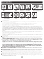
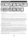
Important Safety Instructions
SAVE THESE INSTRUCTIONS
This manual contains instructions and warnings that should be followed during the installation, operation and storage of this product. Failure to heed these
warnings will void your warranty.
UPS Location Warnings
• Install your UPS indoors, away from excess moisture or heat, conductive contaminants, dust or direct sunlight.
• For best performance, keep the indoor temperature between 32º F and 104º F (0º C and 40º C).
• Leave adequate space around all sides of the UPS for proper ventilation.
• Do not mount unit with its front or rear panel facing down (at any angle). Mounting in this manner will seriously inhibit the unit’s internal cooling,
eventually causing product damage not covered under warranty.
UPS Connection Warnings
• Connect your UPS directly to a properly grounded AC power outlet. Do not plug the UPS into itself; this will damage the UPS.
• Do not modify the UPS’s plug, and do not use an adapter that would eliminate the UPS’s ground connection.
• Do not use extension cords to connect the UPS to an AC outlet. Your warranty will be voided if anything other than Tripp Lite surge suppressors are used to
connect your UPS to an outlet.
• If the UPS receives power from a motor-powered AC generator, the generator must provide clean, ltered, computer-grade output.
Equipment Connection Warnings
• Use of this equipment in life support applications where failure of this equipment can reasonably be expected to cause the failure of the life support
equipment or to signicantly affect its safety or effectiveness is not recommended. Do not use this equipment in the presence of a ammable anesthetic
mixture with air, oxygen or nitrous oxide.
• Do not connect surge suppressors or extension cords to the output of your UPS. This might damage the UPS and will void the surge suppressor and UPS
warranties.
Battery Warnings
• Your UPS does not require routine maintenance. Do not open your UPS for any reason. There are no user-serviceable parts inside.
• Batteries can present a risk of electrical shock and burn from high short-circuit current. Observe proper precautions. Do not dispose of the batteries in
a re. Do not open the UPS or batteries. Do not short or bridge the battery terminals with any object. Unplug and turn off the UPS before performing
battery replacement. Use tools with insulated handles. There are no user-serviceable parts inside the UPS. Battery replacement should be performed only
by authorized service personnel using the same number and type of batteries (Sealed Lead-Acid). The batteries are recyclable. Refer to your local codes
for disposal requirements or visit www.tripplite.com/UPSbatteryrecycling for recycling information. Tripp Lite offers a complete line of UPS System
Replacement Battery Cartridges (R.B.C.).Visit Tripp Lite on the Web at www.tripplite.com/support/battery/index.cfm to locate the specic replacement
battery for your UPS.
• Do not attempt to add external batteries to the UPS.
Quick Installation
1
Plug the UPS into a grounded outlet.
2
Turn the UPS on: Press and hold the ON/OFF/TEST button for one second to turn the UPS on. The UPS alarm will beep once briey after one second has
passed. NOTE: The UPS will not turn on, even if connected to live utility power, until it is turned on using the ON/OFF/TEST button.
3
Plug your equipment into the UPS: Select outlets (see Basic Operation section) will provide battery backup and surge protection; connect your computer,
monitor and other critical devices here.* Select outlets (see Basic Operation section) will provide surge protection only; connect your printer and other non-
essential devices here.
* Your UPS is designed to support electronic equipment only. You will overload the UPS if the total VA ratings for all the equipment you connect to the Battery Backup Protected/Surge Protected outlets
exceeds the UPS’s Output Capacity. To find your equipment’s VA ratings, look on their nameplates. If the equipment is listed in amps, multiply the number of amps by 120 to determine VA. (Example: 1
amp × 120 = 120 VA). If you are unsure if you have overloaded the Battery Backup Protected/Surge Protected outlets, run a self-test (see “ON/OFF/TEST” Button description).

3
Optional Installation (Select Models Only)
Select models feature Tel/DSL surge suppression and USB or DB9 communication capabilities. These connections are optional. The UPS System will
function properly without these connections.
Tel/DSL Line Surge Suppression: Select UPS models can protect equipment against surges over a single phone line. Using telephone cords, connect your
wall jack to the UPS jack marked with a “
” symbol. Connect your equipment to the UPS jack marked with a “
” symbol. Make sure the equipment you
connect to the UPS’s jacks is also protected against surges on the AC line.
USB or DB9 Communications: Select UPS models feature a communication port that can be connected to any computer, enabling PowerAlert Software to
automatically save open les and perform unattended shutdown in the event of a power failure. Connect one end of the included communication cable to the
communication port on the side of your UPS System. Connect the other end of the included cable (featuring either a USB or DB9 connector, depending on model)
to the communication port on your computer. If PowerAlert Software is included with your UPS, insert the CD into the CD tray of your computer and follow the
installation instructions. If PowerAlert Software is not included, you can download the software FREE from Tripp Lite’s website at www.tripplite.com.
ECO Energy-Saving Feature
The ECO feature allows your UPS system to save energy by automatically turning off designated outlets when your computer is turned off or in standby
mode. The ECO feature is disabled by default.
Follow these steps to enable the ECO feature:
1
Use the included USB cable to connect your UPS system to your computer.
2
Connect your nonessential peripheral devices to the ECO outlets, marked “ECO” on your UPS system. Make sure that any devices connected to the ECO
outlets can be turned off without interrupting your Internet connection, local network or other essential services.
3
While your UPS system is turned on and operating normally from utility power, use a small tool to press and hold the “ECO CONTROL” button for 1
second. Release the button when you hear a beep. The green “ECO STATUS” LED should now be lit, indicating that the ECO feature has been enabled.
4
When the UPS system detects that your computer has been turned off or in standby mode for approximately 3 minutes, it will turn off the ECO outlets.
(The 3-minute delay ensures that the ECO outlets remain powered during a reboot, momentary cable disconnection or similar transitory event.)
The green
“ECO STATUS” LED will blink every 5 seconds to indicate that the ECO outlets have been turned off automatically by your UPS system.
Follow these steps to disable the ECO feature:
1
While your UPS system is turned on and operating normally from utility power, press and hold the “ECO CONTROL” button for 1 second. Release the
button when you hear a beep. The green “ECO STATUS” LED should now be off, indicating that the ECO feature has been disabled.
Note: The ECO outlets provide surge and noise protection, but they do not provide battery backup. During a power failure, the ECO outlets will
be off regardless of whether the ECO feature is enabled or disabled.

4
Basic Operation
ON/OFF/TEST
Button
ON/OFF LED OVERLOAD/
CHECK
BATTERY LED
Battery Backup/
Surge Protected
Outlets
Surge-Only
Protected Outlets
Communication Port
(Select models only. For use with
included USB or DB9 cable.)
Tel/DSL Jacks
(Select models only.)
Resettable Circuit
Breaker
ECO CONTROL
Button
ECO STATUS
LED
Surge-Only Protected
ECO Outlets
1
“ON/OFF/TEST” Button
• To turn the UPS on: Press and hold the ON/OFF/TEST Button for one second.* If utility power is absent, pressing the Button will “cold-start” the UPS,
i.e. turn it on and supply power from its batteries.**
• To turn the UPS off: Press and hold the ON/OFF/TEST Button for one second.* The UPS will be turned completely off (deactivated).
• To run a Self-Test: With your UPS plugged in and turned ON, press and hold the ON/OFF/TEST button for three seconds.
* The alarm will beep once briefly after one second has passed. **If fully charged.
CAUTION! To perform a self-test, you must hold the ON/OFF/TEST button continuously for three seconds; if you release the button too early,
you will turn the UPS system OFF and cut power to connected equipment loads. To ensure you hold the button for the correct length of time, do
not release the button until you hear the UPS System’s audible alarm beep twice. The first beep occurs after one second and indicates that the UPS
will turn OFF if the button is released. The second beep occurs after three seconds and indicates that the UPS will perform a self-test if the button
is released.
The test will last approximately 10 seconds as the UPS switches to battery to test its load capacity and charge. All LEDs will be lit and the UPS alarm will
sound. See LED descriptions below to determine the results of the Self-Test.
Note: You can leave connected equipment on during a self-test.
CAUTION! Do not unplug your UPS to test its batteries. This will remove safe electrical grounding and may introduce a damaging surge into your
network connections.
2
“ON/OFF” LED: This green LED lights continuously to indicate that the UPS is ON and supplying your equipment with AC power either from a utility
source or from the UPS’s internal batteries. If the UPS’s alarm is sounding (4 short beeps followed by a pause), the UPS is operating from its internal
batteries.
3
“OVERLOAD/CHECK BATTERY” LED: This red LED lights continuously after a self-test to indicate the capacity of the battery-supported outlets has
been exceeded. To clear the overload, unplug some of your equipment from the battery-supported outlets; then use the ON/OFF/TEST button to run a Self-
Test. If the UPS continues to detect an overload, remove more equipment and repeat the self test until successful.
CAUTION! Any overload that is not corrected by the user immediately following a self-test may cause the UPS to shut down and cease supplying
output power in the event of a blackout or brownout. The LED flashes to indicate the battery needs to be recharged or replaced. If the LED flashes
(and a continuous alarm sounds) during a prolonged blackout or brownout, the UPS’s batteries are nearly out of power; you should save files and
shut down your equipment immediately. If the LED flashes following a UPS self-test (after the UPS is turned ON), it may indicate that the battery
needs to be replaced. Allow the UPS to recharge continuously for 12 hours; then use the ON/OFF/TEST button to run a Self Test. If the LED
continues to flash, contact Tripp Lite for service. Should your UPS require battery replacement, visit Tripp Lite on the web at www.tripplite.com/
support/battery/index.cfm to locate the specific replacement battery for your UPS.
4
Battery Backup Protected/Surge Protected Outlets: Provide both battery backup and surge protection. Plug your computer, monitor and other critical
equipment into these outlets. NOTE: DO NOT PLUG LASER PRINTERS INTO THESE OUTLETS.
5
Surge-Only Protected Outlets: Provide surge and line noise protection, not battery backup. Plug equipment (such as a printer, scanner or fax machine)
that does not require battery backup during a utility power failure into these outlets.
6
Communication Port (Select models only.): This port connects your UPS System to any computer, enabling PowerAlert Software to automatically save
open les and perform unattended shutdown in the event of a power failure. Use with included cable (featuring either a USB or DB9 connector, depending on
model). Connecting your equipment to this port is optional. Your UPS will work properly without this connection. See Optional Installation section for details.
7
Tel/DSL Line Protection Jacks (Select models only.): These jacks protect equipment against surges over a single phone line. Select models feature a
built-in splitter (one jack in/two jacks out), allowing you to connect two devices sharing a single line. Connecting your equipment to these jacks is optional.
Your UPS will work properly without this connection.
1 2 3 4 5 6
7 8 9 10 11
B
A

5
Basic Operation (Continued)
8
Resettable Input Circuit Breaker: Protects your electrical circuit from overcurrent draw from the UPS load. If this breaker trips, remove some of the load,
then reset it by pressing it in.
9
“ECO CONTROL” Button: Use this button
A
to enable or disable the ECO feature. See the ECO Energy-Saving Feature section for more information.
10
“ECO STATUS” LED: This green LED
B
lights when the ECO feature has been enabled. The LED blinks every 5 seconds when the UPS system has
turned off the ECO outlets to conserve energy. See the ECO Energy-Saving Feature section for more information.
11
Surge-Only Protected ECO Outlets: These outlets provide surge and noise protection, but not battery backup. Your UPS system can save energy by
automatically turning off these outlets when it detects that your computer is turned off or in standby mode. Make sure that any devices connected to the
ECO outlets can be turned off without interrupting your Internet connection, local network or other essential services. See the ECO Energy-Saving Feature
section for more information.
Battery Replacement (bottom panel, not shown): Under normal conditions, the original battery in your UPS will last several years. Battery replacement
should be performed only by qualied service personnel. During battery replacement, qualied service personnel should refer to “Battery Warnings” in the
Safety section and should observe the following procedure: turn the UPS off, unplug the power cord and remove the two screws on the UPS bottom panel to
access the internal battery. Tripp Lite offers a complete line of replacement batteries at www.tripplite.com.
Storage and Service
Storage
To avoid battery drain, all connected equipment should be turned off and disconnected from the UPS. Press and hold the ON/OFF/TEST switch for one second.
Your UPS will be completely turned off (deactivated), and will be ready for storage. If you plan on storing your UPS for an extended period, fully recharge the
UPS batteries every three months. Plug the UPS into a live AC outlet, turn it on by pressing and holding the ON/OFF/TEST switch for one second, and allow
the batteries to recharge for 4 to 6 hours. If you leave your UPS batteries discharged for a long period of time, they will suffer a permanent loss of capacity.
Service
A variety of Extended Warranty and On-Site Service Programs are also available from Tripp Lite. For more information on service, visit www.tripplite.com/
support. Before returning your product for service, follow these steps:
1. Review the installation and operation procedures in this manual to insure that the service problem does not originate from a misreading of the instructions.
2. If the problem continues, do not contact or return the product to the dealer. Instead, visit www.tripplite.com/support.
3. If the problem requires service, visit www.tripplite.com/support and click the Product Returns link. From here you can request a Returned Material
Authorization (RMA) number, which is required for service. This simple on-line form will ask for your unit’s model and serial numbers, along with other
general purchaser information. The RMA number, along with shipping instructions will be emailed to you. Any damages (direct, indirect, special or
consequential) to the product incurred during shipment to Tripp Lite or an authorized Tripp Lite service center is not covered under warranty. Products shipped
to Tripp Lite or an authorized Tripp Lite service center must have transportation charges prepaid. Mark the RMA number on the outside of the package. If the
product is within its warranty period, enclose a copy of your sales receipt. Return the product for service using an insured carrier to the address given to you
when you request the RMA.

6
Warranty Registration
Visit www.tripplite.com/warranty today to register the warranty for your new Tripp Lite product. You’ll be automatically entered into a drawing for a chance
to win a FREE Tripp Lite product! *
* No purchase necessary. Void where prohibited. Some restrictions apply. See website for details.
FCC Part 68 Notice (United States Only)
If your Modem/Fax Protection causes harm to the telephone network, the telephone company may temporarily discontinue your service. If possible, they will
notify you in advance. If advance notice isn’t practical, you will be notified as soon as possible. You will be advised of your right to file a complaint with the FCC.
Your telephone company may make changes in its facilities, equipment, operations or procedures that could affect the proper operation of your equipment. If it
does, you will be given advance notice to give you an opportunity to maintain uninterrupted service. If you experience trouble with this equipment’s Modem/Fax
Protection, please call Tripp Lite Technical Support at (773) 869-1234 for repair/warranty information. The telephone company may ask you to disconnect this
equipment from the network until the problem has been corrected or you are sure the equipment is not malfunctioning. There are no repairs that can be made
by the customer to the Modem/Fax Protection. This equipment may not be used on coin service provided by the telephone company. Connection to party lines
is subject to state tariffs. (Contact your state public utility commission or corporation commission for information.)
FCC Radio/TV Interference Notice (U.S. only)
Note: This equipment has been tested and found to comply with the limits for a Class B digital device, pursuant to Part 15 of the FCC Rules. These limits are
designed to provide reasonable protection against harmful interference in a residential installation. This equipment generates, uses and can radiate radio
frequency energy, and if not installed and used in accordance with the instruction manual, may cause interference to radio communications. However, there is
no guarantee that interference will not occur in a particular installation. If this equipment does cause harmful interference to radio or television reception, which
can be determined by turning the equipment off and on, the user is encouraged to try to correct the interference using one or more of the following measures:
reorient or relocate the receiving antenna; increase the separation between the equipment and the receiver; connect the equipment into an outlet on a circuit
different from that which the receiver is connected; consult the dealer or an experienced radio/television technician for help. The user must use shielded cables
and connectors with this product. Any changes or modifications to this product not expressly approved by the party responsible for compliance could void the
user’s authority to operate the equipment. This device complies with part 15 of the FCC rules. Operation is subject to the following 2 conditions: (1) This device
may not cause harmful interference, and (2) This device must accept any interference received, including interference that may cause undesired operation.
Equipment Attachment Limitations (models with the Industry Canada label in Canada only)
NOTICE: The Industry Canada label identifies certified equipment. This certification means that the equipment meets the telecommunications network
protective, operational and safety requirements as prescribed in the appropriate Terminal Equipment Technical Requirements Document(s). The Department
does not guarantee the equipment will operate to the user’s satisfaction.
Before installing this equipment, users should ensure that it is permissible to be connected to the facilities of the local telecommunications company. The
equipment must also be installed using an acceptable method of connection. The customer should be aware that the compliance with the above conditions
might not prevent degradation of service in some situations.
Repairs to certified equipment should be coordinated by a representative designated by the supplier. Any repairs or alterations made by the user to this
equipment, or equipment malfunctions, may give the telecommunications company cause to request the user to disconnect the equipment.
Users should ensure for their own protection that the electrical ground connections of the power utility, telephone lines and internal metallic water pipe system,
if present, are connected together. This precaution may be particularly important in rural areas. Caution: Users should not attempt to make connections
themselves, but should contact the appropriate electric inspection authority, or electrician, as appropriate.
Note on Labeling
Two symbols are used on the label.
V~ : AC Voltage
V
: DC Voltage
Regulatory Compliance Identification Numbers
For the purpose of regulatory compliance certifications and identification, your Tripp Lite product has been assigned a unique series number. The series number can be found on the product
nameplate label, along with all required approval markings and information. When requesting compliance information for this product, always refer to the series number. The series number
should not be confused with the marking name or model number of the product.
Tripp Lite follows a policy of continuous improvement. Product specifications are subject to change without notice.
1111 W. 35th Street, Chicago, IL 60609 USA
www.tripplite.com/support
200912079 • 932806-EN

7
Manual de operación
Sistemas UPS ECO
Entrada de 120V AC
No conveniente para los usos móviles
Instrucciones de seguridad importantes 8
Instalación rápida 8
Instalación opcional 9
Característica de Ahorro de Energía de ECO 9
Operación básica 10
Almacenamiento y Servicio 11
English 1
Français 13
1111 W. 35th Street, Chicago, IL 60609 USA
www.tripplite.com/support
© 2009 Tripp Lite. Todos los derechos reservados.
Page is loading ...
Page is loading ...
Page is loading ...
Page is loading ...
Page is loading ...
Page is loading ...
Page is loading ...
Page is loading ...
Page is loading ...
Page is loading ...
Page is loading ...
-
 1
1
-
 2
2
-
 3
3
-
 4
4
-
 5
5
-
 6
6
-
 7
7
-
 8
8
-
 9
9
-
 10
10
-
 11
11
-
 12
12
-
 13
13
-
 14
14
-
 15
15
-
 16
16
-
 17
17
-
 18
18


Tripp Lite ECO UPS Systems Owner's manual
- Type
- Owner's manual
Ask a question and I''ll find the answer in the document
Finding information in a document is now easier with AI
in other languages
Related papers
-
Tripp Lite BC Internet Owner's manual
-
Tripp Lite ECO850LCD User manual
-
Tripp Lite AVR750UTAA Owner's manual
-
Tripp-Lite OMNIVS1000 Owner's manual
-
-
-
-
-
Tripp Lite AV550SC User manual
-
Other documents
-
 bXterra 350VA UPS BG350 Standby UPS Battery Backup, 6 Outlets, Easy Mute Button, RJ11, Energy Star, LEDs, Contoured Design, Compact User manual
-
Dynex DX-800U User manual
-
Cyber Power UT1000G User manual
-
Tecnoware UPS ECO 0.85 Specification
-
Legrand KEOR PDU Single Phase UPS User manual
-
Koblenz 7016 USB/R Operation & Instruction Manual
-
AmazonBasics B073Q48YGF, B073Q3BSPG Surge Protector Battery Power Backup User guide
-
-
RocketFish RF-AVS7ES User manual
-
