Tripp Lite SRW12UHD & SRW18UHD Wall-Mounted SmartRack Enclosure Owner's manual
- Category
- Racks
- Type
- Owner's manual

Table of Contents
1. Important Safety Instructions 2
2. Overview 2
3. Feature Identification 3
4. Enclosure Installation 4
4.1 Preparation 4
4.2 Leveling the Enclosure 4
4.3 Ground Connection 4
5. Enclosure Configuration 5
5.1 Door Locks 5
5.2 Cable Access and Management 5
5.3 Mounting Rails 5
5.4 Adjusting Mounting Rail Depth 5
6. Wall Mounting the Enclosure 6
7. Equipment Installation 7
7.1 Installing or Removing Cage Nuts 7
8. Specifications 7
9. Storage and Service 8
10. Warranty & Warranty Registration 8
Español 9
Français 17
Owner’s Manual
Wall-Mounted
SmartRack
®
Enclosure
Models: SRW12UHD & SRW18UHD
1111 W. 35th Street, Chicago, IL 60609 USA • www.tripplite.com/support
Copyright © 2014 Tripp Lite. All trademarks are the sole property of their respective owners.

2
1. Important Safety Instructions
2. Overview
SAVE THESE INSTRUCTIONS
This Manual contains instructions and warnings that must be followed during the installation and operation of the product described in this manual. Failure to
comply may invalidate the warranty and cause property damage or personal injury.
• Keep the enclosure in a controlled indoor environment, away from moisture, temperature extremes, flammable liquids and gasses, conductive
contaminants, dust and direct sunlight.
• Leave adequate space at the front and rear of the enclosure for proper ventilation. Do not block, cover or insert objects into the external ventilation
openings of the enclosure.
• The enclosure is extremely heavy. Use caution when handling the enclosure. Do not attempt to unpack, move or install it unassisted. Use a
mechanical device such as a forklift or pallet jack to move the enclosure in the shipping container.
• Do not place any object on the enclosure, especially containers of liquid, and do not attempt to stack the enclosures.
• Inspect the shipping container and the enclosure for shipping damage. Do not use the enclosure if it is damaged.
• Leave the enclosure in the shipping container until it has been moved as close to the final installation location as possible.
• Install the enclosure in a structurally sound area capable of handling the load, or on a level floor that is able to bear the weight of the enclosure, all
equipment that will be installed in the enclosure and any other enclosures and/or equipment that will be installed nearby.
• Use caution when cutting packing materials. The enclosure could be scratched, causing damage not covered by the warranty.
• Save all packing materials for later use. Repacking and shipping the enclosure without the original packing materials may cause product damage
that will void the warranty.
• Do not reship the enclosure with additional equipment unless the enclosure was shipped with a special shock pallet (“SP1” models only). The
combined weight of the enclosure and installed equipment must not exceed the load capacity of the pallet. Tripp Lite is not responsible for any
damage that occurs during reshipment.
• Use of this equipment in life support applications where failure of this equipment can reasonably be expected to cause the failure of the life support
equipment or to significantly affect its safety or effectiveness is not recommended. Do not use this equipment in the presence of a flammable
anesthetic mixture with air, oxygen or nitrous oxide.
SmartRack Enclosures accommodate all standard 19-inch rackmount equipment, regardless of vendor, and ship fully assembled for quick and easy
deployment.

3
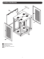
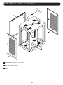
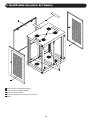
3. Feature Identification
1
Locking/Removable Side Doors
2
Locking/Removable Front Panel
3
Vertical Mounting Rails
4
Removable Cable Access Hole Covers
5
Vents
1
2
3
1
4
5

4
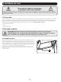
4. Enclosure Installation
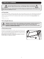
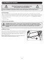
4.1 Preparation
4.3 Ground Connection
Caution! Read All Instructions and Warnings Before Installation!
Warning: Rack enclosures can be extremely heavy. Do not attempt to unpack, move or install the enclosure without assistance. Use
extreme caution when handling the enclosure and be sure to follow all handling and installation instructions. Do not attempt to install
equipment without first stabilizing the enclosure.
The enclosure must be installed in a structually sound area that is able to bear the weight of the enclosure, all the equipment that will be installed in the
enclosure and any other enclosures and/or equipment that will be installed nearby. Before unpacking the enclosure, you should transport the shipping
container closer to the final installation location to minimize the distance you will need to move the unit after the protective packaging has been
removed. If you plan to store the enclosure for an extended period before installation, follow the instructions in the Storage and Service section.
All parts of the enclosure are grounded to the frame of the enclosure. Connect one of the
two quick-disconnect grounding wires to the hole provided on the inside of either of the
side doors and connect the other quick-disconnect grounding wire to any of the enclosure
studs. Then connect your facility’s earth ground connection to the grounding stud not used
by door connections with an 8 AWG (3.264 mm) wire.
Warning: Attach each enclosure to earth ground separately. Do not use the
enclosure without an earth ground connection.
You will need these tools:
• Level
• Phillips-HeadScrewdriver
4.2 Leveling the Enclosure
WARNING: Level the enclosure before attempting to install equipment. Install the enclosure in a
structurally sound area with a vertically-level wall that is able to bear the weight of the
enclosure, all equipment that will be installed in the enclosure and any other enclosures and/or
equipment that will be installed nearby.
EARTH
GROUND

5
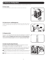
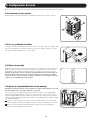
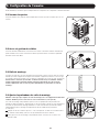
5. Enclosure Configuration
Before installation, make sure to plan the location and arrangement of components within the enclosure.
5.1 Door Locks
The side doors and front panel contain locks that are accessible with the included keys.
5.2 Cable Access and Management
Two additional openings can be found on both the top and bottom of the cabinet. Each of the four
openings on the top and bottom of the cabinet can be closed by screwing in the removable cable
access panels.
5.3 Mounting Rails
5.4 Adjusting Mounting Rail Depth
The enclosure comes with mounting rails that have both square and tapped holes for mounting rack
equipment. To install equipment, use the included cage nuts and other hardware. (See page 7 for
installation of cage nuts.) Warning: Be sure to have the enclosure securely mounted to the
wall before mounting any equipment inside. Also be sure to have all the right adjustments
on your rails before mounting equipment. (See below for Adjusting Mounting Rail Depth.)
Warning: Do not attempt to adjust rails while equipment is installed in the enclosure.
Do not attempt to use rails without screws installed. (2 per rail.)
The 4 mounting rails are pre-installed to accommodate equipment with a mounting depth of 20.5
inches (521 mm). Do not adjust the mounting rails unless your equipment requires a different
mounting depth. The front and rear sets of rails can be adjusted independently for mounting of
equipment with depths between 3 inches (76 mm) and 32.5 inches (826 mm).
1
Each rail is connected to the enclosure with 2 screws: 1 in the upper corner and another in the
lower corner. Using a Phillips-head screwdriver, remove the screws that fasten the rails to the
enclosure.
2
Slide the mounting rails to the desired depth and reattach them using the screws you removed
in Step 1.
1
2

6
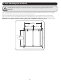
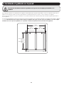
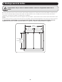
6. Wall Mounting the Enclosure
Warning: Do not attempt to mount the enclosure to the wall with equipment mounted in the
enclosure.
There are 6 keyhole cutouts on the back door of the enclosure. Each keyhole can accommodate an M10 or 3/8” bolt. The holes are 16” apart
horizontally and 29” apart vertically, to match typical stud spacing, as shown in diagram.
Note: Do not lift the enclosure into mounting position with the doors installed. Always remove doors prior to lifting to reduce the enclosure’s weight.
Using a level, measure to position your mounting areas precisely. Use appropriate fasteners (not included) to secure the enclosure to the wall.
Warning: The area you plan to mount the enclosure to must be able to withstand the weight of the enclosure and all mounted
equipment. For the weight of the enclosure and its capacity, refer to the Specifications section on page 7.
18U: 29 in.
736.6 mm
12U: 18.5 in.
469.8 mm
16 in.
406.4 mm
16 in.
406.4 mm
32 in.
812.8 mm

7
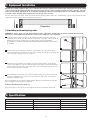
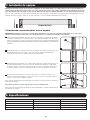
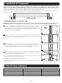
7. Equipment Installation
7.1 Installing or Removing Cage Nuts
Warning: Do not install equipment until you have stabilized the enclosure. Install heavier equipment first and install it towards the bottom
of the enclosure. Install equipment starting from the bottom of the enclosure and proceeding toward the top of the enclosure - never the
reverse. If using sliding equipment rails, be careful when extending the rails. Do not extend more than one set of sliding equipment rails
at one time. Avoid extending sliding equipment rails near the top of the enclosure.
Note: The square holes in the middle of each rack unit are numbered and also include a small notch to aid identification. A single rack unit includes the space
occupied by the numbered hole and the holes directly above and below.
To Remove Cage Nuts, Reverse Steps 1-3
Note: You may wish to use a cage nut tool (user-supplied) to aid cage nut installation and removal.
WARNING: The flanges of the cage nuts should engage the sides of the square opening in the rail, not the top and bottom. Follow the
instructions in your equipment documentation to ensure proper installation of your equipment.
1
Locate the numbered square openings in the mounting rails where you plan to install your
equipment. You will install cage nuts (included) into the square openings in order to provide an
attachment point for the mounting screws (included). Note: Consult your equipment
documentation to determine how many cage nuts will be required and where they will need to
be installed.
2
From the inside of the mounting rail, insert one of the flanges of the cage nut through the
square opening. Press it against the side of the square opening. Each flange should engage one
side of the square opening, not the top or bottom.
3
Compress the cage nut at the sides slightly to allow the remaining flange to fit through the
square opening. When the cage nut is properly installed, both flanges will protrude through the
square opening and will be visible on the outer surface of the mounting rail. Repeat steps 1-3
until all required cage nuts are installed.
4
After installing the required cage nuts, use the included mounting screws and cup washers to
secure your equipment to the rack rail. Place the cup washers between the screws and the
equipment mounting brackets.
Note: Your equipment may also include mounting hardware. Read the mounting instructions that came
with your equipment before installing your equipment.
8. Specifications
Model SRW12UHD SRW18UHD
Dimensions(HxWxD) 24.46 x 36.1 x 24.77” (621 x 917 x 629 mm) 35.96 x 36.1 x 24.77” (913 x 917 x 629 mm)
Unit Weight 101.4 lb (46 kg) 119.9 lb (54.4 kg)
Load Capacity 500 lb (226.8 kg) 500 lb (226.8 kg)
Mounting Depth (Adjustable) 19.36 – 30.36” (491.74 – 771.14 mm) 19.36 – 30.36” (491.74 – 771.14 mm)
20
19
18
22
21
20
19
18
22
21
20
19
18
22
21
20
19
18
22
21
24
25
26
27
28
29
23
22
21
20
19
18
24
25
26
27
28
29
23
22
21
20
19
18
24
24
2
1 Rack Unit
1
2
3
4

8
5-Year Limited Warranty
Seller warrants this product, if used in accordance with all applicable instructions, to be free from original defects in material and workmanship for a
period of 5 years from the date of initial purchase. If the product should prove defective in material or workmanship within that period, Seller will repair
or replace the product, at its sole discretion.
THISWARRANTYDOESNOTAPPLYTONORMALWEARORTODAMAGERESULTINGFROMACCIDENT,MISUSE,ABUSEORNEGLECT.SELLERMAKES
NOEXPRESSWARRANTIESOTHERTHANTHEWARRANTYEXPRESSLYSETFORTHHEREIN.EXCEPTTOTHEEXTENTPROHIBITEDBYAPPLICABLELAW,
ALLIMPLIEDWARRANTIES,INCLUDINGALLWARRANTIESOFMERCHANTABILITYORFITNESS,ARELIMITEDINDURATIONTOTHEWARRANTYPERIOD
SETFORTHABOVE;ANDTHISWARRANTYEXPRESSLYEXCLUDESALLINCIDENTALANDCONSEQUENTIALDAMAGES.(Somestatesdonotallow
limitations on how long an implied warranty lasts, and some states do not allow the exclusion or limitation of incidental or consequential damages, so
the above limitations or exclusions may not apply to you. This warranty gives you specific legal rights, and you may have other rights which vary from
jurisdiction to jurisdiction).
WARNING:Theindividualusershouldtakecaretodeterminepriortousewhetherthisdeviceissuitable,adequateorsafefortheuseintended.Since
individual applications are subject to great variation, the manufacturer makes no representation or warranty as to the suitability or fitness of these
devices for any specific application.
Warranty Registration
Visitwww.tripplite.com/warrantytodaytoregisterthewarrantyforyournewTrippLiteproduct.You’llbeautomaticallyenteredintoadrawingfora
chance to win a FREE Tripp Lite product!*
*Nopurchasenecessary.Voidwhereprohibited.Somerestrictionsapply.Seewebsitefordetails.
Regulatory Compliance Identification Numbers
For the purpose of regulatory compliance certifications and identification, your Tripp Lite product has been assigned a unique series number. The series
number can be found on the product nameplate label, along with all required approval markings and information. When requesting compliance
information for this product, always refer to the series number. The series number should not be confused with the marketing name or model number
of the product.
Tripp Lite has a policy of continuous improvement. Specifications are subject to change without notice.
9. Storage and Service
10. Warranty and Warranty Registration
Storage
The enclosure should be stored in a controlled indoor environment, away from moisture, temperature extremes, flammable liquids and gasses,
conductive contaminants, dust and direct sunlight. Store the enclosure in its original shipping container if possible.
Service
YourTrippLiteproductiscoveredbythewarrantydescribedinthismanual.AvarietyofExtendedWarrantyandOn-SiteServiceProgramsarealso
available from Tripp Lite. For more information on service, visit www.tripplite.com/support. Before returning your product for service, follow these steps:
1. Review the installation and operation procedures in this manual to insure that the service problem does not originate from a misreading of the
instructions.
2. If the problem continues, do not contact or return the product to the dealer. Instead, visit www.tripplite.com/support.
3. If the problem requires service, visit www.tripplite.com/support and click the Product Returns link. From here you can request a Returned Material
Authorization (RMA) number, which is required for service. This simple on-line form will ask for your unit’s model and serial numbers, along with
other general purchaser information. The RMA number, along with shipping instructions will be emailed to you. Any damages (direct, indirect, special
or consequential) to the product incurred during shipment to Tripp Lite or an authorized Tripp Lite service center is not covered under warranty.
Products shipped to Tripp Lite or an authorized Tripp Lite service center must have transportation charges prepaid. Mark the RMA number on the
outside of the package. If the product is within its warranty period, enclose a copy of your sales receipt. Return the product for service using an
insured carrier to the address given to you when you request the RMA.
1111 W. 35th Street, Chicago, IL 60609 USA • www.tripplite.com/support
Page is loading ...
Page is loading ...
Page is loading ...
Page is loading ...
Page is loading ...
Page is loading ...
Page is loading ...
Page is loading ...
Page is loading ...
Page is loading ...
Page is loading ...
Page is loading ...
Page is loading ...
Page is loading ...
Page is loading ...
Page is loading ...
-
 1
1
-
 2
2
-
 3
3
-
 4
4
-
 5
5
-
 6
6
-
 7
7
-
 8
8
-
 9
9
-
 10
10
-
 11
11
-
 12
12
-
 13
13
-
 14
14
-
 15
15
-
 16
16
-
 17
17
-
 18
18
-
 19
19
-
 20
20
-
 21
21
-
 22
22
-
 23
23
-
 24
24


Tripp Lite SRW12UHD & SRW18UHD Wall-Mounted SmartRack Enclosure Owner's manual
- Category
- Racks
- Type
- Owner's manual
Ask a question and I''ll find the answer in the document
Finding information in a document is now easier with AI
in other languages
Related papers
-
Tripp Lite Cable Manager Tray (1U) Installation guide
-
Tripp-Lite SmartRack SR18UB Owner's manual
-
Tripp Lite SR12UB Owner's manual
-
-
-
-
-
-
Tripp Lite SmartRack SR42UBZ4 Owner's manual
-
Other documents
-
Legrand Enclosure Extenders - 364450-03/364450-04 Operating instructions
-
CyberPower CR6U61003 User manual
-
Cyber Power CR6U61003 User manual
-
CyberPower CR12U51001 User manual
-
CyberPower CR6U61001 User manual
-
Legrand Enclosure Extenders - 364450-03/364450-04 Operating instructions
-
Power Fist 8442923 Owner's manual
-
 AccuScreens APM1024WTR Installation guide
-
Carlson 6021 DS User manual
-
Strong SR-WM-DOOR-12U-PLEXI Owner's manual
