Victron energy 12/60 User manual
- Category
- Battery chargers
- Type
- User manual
This manual is also suitable for
Page is loading ...

CCH012020000-M-bML
Copyrights © 2005 Victron Energy B.V.
All Rights Reserved
This publication or parts thereof, may not be reproduced in any form, by any method, for any
purpose.
For conditions of use and permission to use this manual for publication in other than the
English language, contact Victron Energy B.V.
VICTRON ENERGY B.V. MAKES NO WARRANTY, EITHER EXPRESSED OR IMPLIED,
INCLUDING BUT NOT LIMITED TO ANY IMPLIED WARRANTIES OF
MERCHANTABILITY OR FITNESS FOR A PARTICULAR PURPOSE, REGARDING
THESE VICTRON ENERGY PRODUCTS AND MAKES SUCH VICTRON ENERGY
PRODUCTS AVAILABLE SOLELY ON AN “AS IS” BASIS.
IN NO EVENT SHALL VICTRON ENERGY B.V. BE LIABLE TO ANYONE FOR SPECIAL,
COLLATERAL, INCIDENTAL, OR CONSEQUENTIAL DAMAGES IN CONNECTION WITH
OR ARISING OUT OF PURCHASE OR USE OF THESE VICTRON ENERGY PRODUCTS.
THE SOLE AND EXCLUSIVE LIABILITY TO VICTRON ENERGY B.V., REGARDLESS OF
THE FORM OF ACTION, SHALL NOT EXCEED THE PURCHASE PRICE OF THE
VICTRON ENERGY PRODUCTS DESCRIBED HEREIN.
Victron Energy B.V. reserves the right to revise and improve its products as it sees fit. This
publication describes the state of this product at the time of its publication and may not
reflect the product at all times in the future.

1
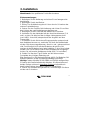
1. Safety and regulatory information
General
• Review related documentation of this product to familiarize
yourself with safety markings and instructions before you operate
the equipment.
• This product has been designed and tested in accordance with
international standards. Only use the equipment for the intended
purpose of application.
• WARNING: RISK OF ELECTRIC SHOCK. The product is used in
conjunction with a permanent energy source (battery). Even if the
equipment is switched off, dangerous electrical voltages may
appear at the in- and/or output terminals. Always disconnect AC
power and battery before maintaining or servicing the product.
A Ground Fault Circuit Interrupter (GFCI) must be installed in the
AC supply circuit.
• There are no user-serviceable parts inside. Do not remove the
front plate or operate the product without the front plate fitted.
Refer all servicing to qualified personnel.
• Never use the product in locations where there is danger of gas-
or dust explosions. Consult your supplier to ensure that the
product is intended for use in conjunction with the battery. Always
apply the battery manufacturer’s safety instructions.
• Caution: never carry heavy loads without assistance.
• Explosive gases can be generated during charging of a lead-acid
battery. Prevent open flame and sparks. Take care of sufficient
ventilation during charging.
• Never try to recharge non-rechargeable batteries.
• A double-pole switch with a minimum contact distance of 3mm
must be incorporated in the fixed mains input wiring of the
installation.

2
Installation
• The installation of this product must be performed by qualified
personnel.
• Always refer to the installation section in the operator’s manual
before applying power to the equipment.
• This is a Safety Class I product (provided with a protective
earthing terminal). An uninterruptible safety earth ground must be
provided at the AC in/output terminals. An additional grounding
point is located at the outside of the product. Whenever it is likely
that the grounding protection has been impaired, the product must
be made inoperative and secured against any unintended
operation; refer to qualified service personnel.
• Make sure that fuses and circuit breakers are provided in the
connecting wires. Never replace a safety component by a different
type. Consult the manual for determining the correct component.
• Make sure that all cables and wiring in the installation are
anchored such that the conductors are relieved from strain and
twisting.
• Before applying power, verify that the available power source
matches the configuration settings of the product as described in
the manual.
• Ensure that the environmental conditions are suitable for
operation of the equipment. Never operate the product in a wet or
in a dusty environment.
• Always allow enough free space around the product for
ventilation and make sure that ventilation vents are not blocked.
• Be sure that the demanded power does not exceed the capacity
of the product.
• This device is a continuous duty automatic charger for
rechargeable open, sealed and gel lead acid batteries
• For supply connection use wires suitable for at least 75°C
(167°F).
• CAUTION: Replace defective cords or wires immediately.

3
Transport and storage
• When storing or transporting the product make certain that mains
power and battery leads are disconnected.
• No liability can be accepted for any transport damage when
equipment is shipped in non-original packaging.
• Store the product in a dry location; storage temperature must be
between –20°C and 60°C.
• Refer to the battery manufacturer manual concerning transport,
storage, charging, recharging and disposal of the battery.

4
2. Description
Technology
The Centaur Charger is a fully high-frequency switched battery
charger. The input is electronically power factor corrected by the
first power stage.
The next stage gives provision for galvanic isolation and a perfect
DC voltage at the output terminals.
The internal electronic parts are protected against moisture and
dirt by means of a special coating, which assures a long lifetime of
your battery charger.
Three high-capacity batteries can be charged simultaneously with
this charger.
Operation
The battery charger charges the battery with 3-stage (Bulk-
Absorption-Float) charging characteristic. It can remain connected
to the battery continuously, without increased gas formation,
caused by overcharging, taking place.
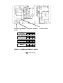
The charger can be used for different types of batteries but the
default settings are for Gel batteries.
For use with other types of batteries please select Lead acid or
AGM by opening front bottom cover and select dipswitch in bottom
left hand corner. See Figure 1.
The full charging current of this Charger is divided in three main
outputs but any one output can supply 100% of power if that is the
only battery connected.

5
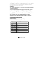
TROUBLESHOOTING
Problem Possible cause Solution
Charger does not function The mains is not ok Measure mains
Input or output fuses are defective Return product to
your dealer
The battery does not get A bad battery connection Check battery
fully charged connection
The battery select switch Select correct
is in wrong setting battery
type (see Fig1)
Battery capacity to large Make sure charger
capacity matches
battery
The battery is being The battery select switch Select correct
overcharged is wrong setting battery
type (see Fig1)
A single cell in battery is defective Replace battery
Too small battery Consult your battery
supplier

6
3. Installation
WARNING: Qualified personnel only
Instructions
1. Mount wall bracket (for top holding) of the battery charger, make
sure it is level.
2. Install three screws.
3. Open cover by removing four screws, on front bottom cover.
4. Put charger on mounting bracket and mark the Bottom of the
two (M6-D-holes) mounting holes.
5. Install M6 screws.
6. Install AC cord to input terminal strip marked E, N, L, be sure to
use the correct size wire (per ABYC regulations) to use for the
input current marked on the label of charger.
7. Cut DC inlet plugs to cable size, then connect battery cables to
DC lugs marked +DC & -DC. The -DC is used common for all
three batteries. If there are less than three batteries, pick any +DC;
all are capable of full current load. Select appropriate size wire
(per ABYC regulations).
8. Select battery type by pushing the appropriate dipswitch at
bottom left corner of board.
Note: This unit is selected for GEL; if you change battery type
DESELECT GEL, (See Figure 1).
Important: Centaur models 12/200, 24/80 and 24/100 are fitted
with 2 boards that operate in parallel. The dipswitches on both
boards should be in the same position
to ensure that both boards
follow the same charge curve.
9. Replace top cover and reinstall four screws on cover.
10. Apply power and verify Green Led is on (bottom left of PC
board, look through bottom left air vents).

7
Location
The Centaur Charger must be installed in a dry, well-ventilated
area.
Too high an ambient temperature has the consequence of lower
output, shorter life or a complete shutdown of the Centaur
Charger.
The Centaur Charger is suitable for floor and wall mounting.
However, for optimum cooling, a vertical position is recommended.
The cables between the Centaur Charger and the battery must be
kept as short as possible to minimize cable losses. Input/output
connections refer to Figure 1.
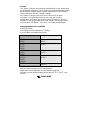
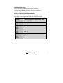
Required tools and cables
• M6 Socket driver.
• Crosshead screwdriver no. 2 Phillips.
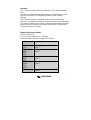
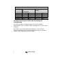
• Battery cables: minimum cable cross-section
Model
Length 0 - 6 m
12/20
24/16
10 mm²
AWG 7
12/30
12/40
24/30
24/40
16 mm²
AWG 5
12/50
12/60
24/60
25 mm²
AWG 3
12/80
12/100
24/80
24/100
35 mm²
AWG 2
12/200
50 mm²
AWG 0

8
Cables longer then 6 m are not recommended.
Cable eyes with M6/8 holes should be used.
For supply connection use wires suitable for at least 75°C (167°F).
CAUTION: Replace defective cords or wires immediately.
Connection sequence
• Disconnect mains.
• Disconnect battery cables from the battery.
• Open front cover.
• Connect battery cables to the charger. Note that there’s only one
“minus”- Use a fuse according the size of the battery charger.
• Connect battery cables to the battery.
• Connect the AC-in by means of a 3-core cable of 2.5 – 4 mm²
flexible core to the AC-in terminal block. Note that a real PE-
connection is strictly necessary.
• Close the front panel.
Charge voltage at appr. 10% of the nominal current
Absorption Float
12V 24V 12V 24V
GEL 14.2 28.4 13.5 27.0
AGM 14.35 28.7 13.3 26.6
LA 14.5 29.0 13.5 27.0
Other 14.85 29.7 13.7 27.4
Important note regarding charge voltage settings
The charge voltages as mentioned above for the different types of
battery are indicative only. Please contact your battery supplier for
advice.
Especially flooded lead acid batteries (“LA” in the table) may
require a different charge voltage, depending on
chemical/mechanical construction.

9
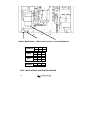
+ + + -DC
Battery Select LED ‘ON’ Indicator AC INPUT
II
LA
II II
II
AGM
II II
II
GEL
II II
II II
Other
II
FIGURE 1 INPUT/ OUTPUT CONNECTIONS

10
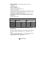
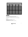
Input Voltage vs. Input Current
Model
Input
Voltage
(Vac)
Input
Current
(Aac)
Input
Voltage
(Vac)
Input
Current
(Aac)
12/20 120 3.35 240 1.75
12/30 120 4.35 240 2.30
12/40 120 6.40 240 3.20
12/50 120 8.00 240 4.00
12/60 120 9.55 240 4.75
12/80 120 12.0 240 6.00
12/100 120 15.0 240 8.00
12/200 120 30.0 240 15.0
24/16 120 4.75 240 2.50
24/30 120 9.00 240 4.55
24/40 120 10.0 240 6.00
24/60 120 15.0 240 9.00
24/80 120 20.0 240 12.0
24/100 120 25.0 240 15.0
Note:
For other input voltages Uin the input current can be calculated as
follows:
Input current = (current at 120Vac) x (120 / Uin)
Example:
Input current at 120Vac: 3,35 Amps
Required: input current at Uin = 110Vac
Answer: input current = 3,35 x (120 / 110) = 3,65 A

11
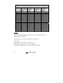
4. Specifications
Centaur Charger
12/20
12/30
24/16
12/40
12/60
24/30
12/80
24/40
12/100
24/60
12/160
24/80
12/200
24/100
Common characteristics
Input voltage: 90 – 265 V Input frequency: 45 – 65 Hz Power factor: 1
Charge voltage ‘absorption’
(V DC)
14,3 / 28,5
(1)
Charge voltage ‘float’
(V DC)
13,5 / 27,0
(1)
Output banks
3
Charge current (A) (2) 20 30/ 16 40 60/ 30 80/ 40 100/ 60 160/ 80 200/ 100
Total output ammeter
Yes
Charge characteristic
IUoU (Three stage charging)
Recommended battery
capacity (Ah)
80 -
200
120-
300
45-
150
160-
400
240-
600
120-
300
320-
800
160-
400
400-
1000
240-
600
640-
1600
320-
800
800-
2000
400-
1000
Temperature sensor
Internal, - 2mV / °C (- 1mV / °F) per cell
Forced cooling
Yes, temperature and current controlled fan
Protection
Output short circuit, over temperature
Operating temp. range
- 20 to 60°C (0 - 140°F)
Ignition protected Yes
Humidity (non condensing)
max 95%
ENCLOSURE
Material & Colour aluminium (blue RAL 5012)
Battery-connection
M6
studs
M6
studs
M8
studs
M8
studs
M8
studs
M8
studs
M8
studs
M8
studs
AC-connection screw-clamp 4 mm² (AWG 6)
Protection category IP 21
Weight kg (lbs) 3,8 (8.4)
3,8
(8.4)
5 (11)
5 (11)
12 (26)
12 (26)
16 (35)
16 (35)
Dimensions
hxwxd in mm
(hxwxd in inches)
355x215
x110
(14.0x8.5
x4.3)
355x215
x110
(14.0x8.5
x4.3)
426x239
x135
(16.8x9.4
x5.3)
426x239
x135
(16.8x9.4
x5.3)
505x255
x130
(19.9x10.0
x5.2)
505x255
x130
(19.9x10.0
x5.2)
505x255
x230
(19.9x10.0
x9.1)
505x255
x230
(19.9x10.0
x9.1)
STANDARDS
Safety
EN 60335-2-29, UL 1236
Emission
EN 55014, EN 61000-3-2, EN 61000-3-3
Immunity
EN 55014-2
1)Standard setting.
Optimum charge/float voltages for Flooded Lead-acid, Gel-Cell or AGM batteries selectable by dip switch.
2) Up to 40 °C (100 °F) ambient.
Output will reduce to approximately 80 % of nominal at 50 °C (120 °F) and 60 % of nominal at 60 °C (140°F).
Page is loading ...
Page is loading ...
Page is loading ...
Page is loading ...
Page is loading ...
Page is loading ...
Page is loading ...
Page is loading ...
Page is loading ...

9
+ + + -DC
Accu selecteren LED ‘Aan’ Indicator AC INPUT
II
LA
II II
II
AGM
II II
II
GEL
II II
II II
Anders
II
FIGUUR 1 INPUT/OUTPUT VERBINDINGEN
Page is loading ...

11
4. Specificaties
Centaur Laders
12/20
12/30
24/16
12/40
12/60
24/30
12/80
24/40
12/100
24/60
12/160
24/80
12/200
24/100
Ingang Ingangsspanning: 90 – 265 V Frequentie: 45 – 65 Hz Power factor: 1
Laadspanning
'absorption' (V DC)
14,3 / 28,5 (1)
Laadspanning 'float'
(V DC)
13,5 / 27,0 (1)
aantal uitgangen 3
Laadstroom (A)
(2)
20 30 / 16 40 60 / 30 80 / 40 100 / 60 160 / 80
200 /
100
Ampère meter Ja
Laadkarakteristiek IUoU (3-traps laadkarakteristiek)
Aanbevolen
accucapaciteit (Ah)
80 -
200
120 -
300
45 -
150
160 -
400
240 -
600
120 -
300
320 -
800
160 -
400
400 -
1000
240 -
600
640 -
1600
320 -
800
800 -
2000
400 -
1000
Temperatuur sensor Intern, - 2mV / °C per cel
Geforceerde koeling Ja, temperatuur en stroom gestuurd
Beveiligingen Kortsluiting en temperatuur
Temperatuur bereik - 20 - 60°C
Ignition protected Ja
Vocht (niet
condenserend)
max 95%
BEHUIZING
Materiaal & kleur aluminium (blauw RAL 5012)
Accu-aansluiting
M6
bouten
M6
bouten
M8
bouten
M8
bouten
M8
bouten
M8
bouten
M8
bouten
M8
bouten
230 V AC-aansluiting schroefklem 2,5 mm²
Beschermklasse IP 21
Gewicht (kg) 3,8 3,8 5 5 12 12 16 16
Afmetingen (hxbxd in
mm)
355x215
x110
355x215
x110
426x239
x135
426x239
x135
505x255
x130
505x255
x130
505x255x1
30
505x255
x230
NORMEN
Veiligheid EN 60335-2-29, UL 1236
Emissie EN 55014, EN 61000-3-2, EN 61000-3-3
Immuniteit EN 55014-2
1) Standaard instelling.
Met dip switches ingestelbaar voor open lood accu’s, gel accu’s of AGM accu’s.
2) Tot 40 °C omgevingstemperatuur.
De uitgangsstroom neemt af tot ca. 80 % van nominaal bij 50 °C en 60 % van nominaal bij 60 °C.
Page is loading ...
Page is loading ...
Page is loading ...
Page is loading ...
Page is loading ...
Page is loading ...
Page is loading ...
Page is loading ...
Page is loading ...
Page is loading ...

10
+ + + - batterie(s)
Sélection type batterie Voyant « marche » Bornier entrée
secteur
II
LA
(acide liquide)
II II
II
AGM
(absorbed glass mat)
II II
II
GEL
(électrolyte gélifié)
II II
II II
Autres
II
FIGURE 1 : CONNEXIONS ENTREE/ SORTIE
Page is loading ...
Page is loading ...
Page is loading ...
Page is loading ...
Page is loading ...
Page is loading ...
Page is loading ...
Page is loading ...
Page is loading ...
Page is loading ...
Page is loading ...
Page is loading ...
Page is loading ...
Page is loading ...

Serial number:
Distributor:
Victron Energy B.V.
The Netherlands
General phone: +31 (0)36 535 97 00
Customer support desk: +31 (0)36 535 97 77
General and Service fax: +31 (0)36 531 16 66
Sales fax: +31 (0)36 535 97 40
E-mail: [email protected]
Internet site: http://www.victronenergy.com
Article number: ISM001001000
Version: 09
Date: 27-02-2007
-
 1
1
-
 2
2
-
 3
3
-
 4
4
-
 5
5
-
 6
6
-
 7
7
-
 8
8
-
 9
9
-
 10
10
-
 11
11
-
 12
12
-
 13
13
-
 14
14
-
 15
15
-
 16
16
-
 17
17
-
 18
18
-
 19
19
-
 20
20
-
 21
21
-
 22
22
-
 23
23
-
 24
24
-
 25
25
-
 26
26
-
 27
27
-
 28
28
-
 29
29
-
 30
30
-
 31
31
-
 32
32
-
 33
33
-
 34
34
-
 35
35
-
 36
36
-
 37
37
-
 38
38
-
 39
39
-
 40
40
-
 41
41
-
 42
42
-
 43
43
-
 44
44
-
 45
45
-
 46
46
-
 47
47
-
 48
48
-
 49
49
-
 50
50
-
 51
51


Victron energy 12/60 User manual
- Category
- Battery chargers
- Type
- User manual
- This manual is also suitable for
Ask a question and I''ll find the answer in the document
Finding information in a document is now easier with AI
in other languages
- français: Victron energy 12/60 Manuel utilisateur
- Deutsch: Victron energy 12/60 Benutzerhandbuch
- Nederlands: Victron energy 12/60 Handleiding
Related papers
-
Victron energy 24/60 User manual
-
Victron energy Centaur User manual
-
-
-
Victron energy MultiPlus 3k Owner's manual
-
-
-
-
-
Other documents
-
Pure Garden M150077 User manual
-
Battery Tender 022-0165-DL-WH User manual
-
 Holmatro TR 5370 LP User manual
-
Paso W-MS24/40 Owner's manual
-
Truma BC 10 Installation Instructions Manual
-
AEG AG 1212 Owner's manual
-
Waeco mobitronic MBC-400, MBC-600, MBC-600a Operating instructions
-
Schumacher ECOBAT EBC1 Automatic Battery Maintainer Owner's manual
-
ULTIMATE SPEED IAN 74798 Datasheet
-
