Craftsman 152219110 Owner's manual
- Category
- Power tools
- Type
- Owner's manual
This manual is also suitable for

truction anu
®
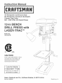
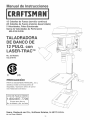
1/3 Horsepower (continuous duty)
2/3 Horsepower (maximum devemoped)
5-Speed, Step Pulley
620 - 3100 R.P.M. Drill Speed Range
1
P
FOR YOUR OWN SAFETY; Read
and foUlow all of the Safety and
Operating Instructions before
Operating this DdH Press.
Customer Helpline
1-800-897-7709
PRease have your Model No.
and SedaR No. availabUe.
Sears, Roebuck and Co., Hoffman Estates, JL 60179 U.S.A.
Part No. OR93515
EspaSoL pg, 31

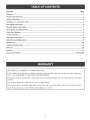
SECTmON PAGE
Warranty..........................................................................................................................................................................2
ProductSpecifications...................................................................................................................................................3
Safetymnstructions.........................................................................................................................................................4
Guidelinesforextension cords ..................................................................................................................................... 5
Grounding mnstructions .................................................................................................................................................. 6
Specific Safety mnstructions .......................................................................................................................................... 7
Accessories and Attachments ...................................................................................................................................... 8
Know Your Machine ....................................................................................................................................................... 9
Carton Contents ............................................................................................................................................................ 11
AssembJy mnstructions ................................................................................................................................................. 12
Operations and Adjustment ........................................................................................................................................ 17
Maintenance .................................................................................................................................................................. 24
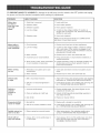
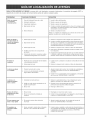
Troubleshooting Guide ................................................................................................................................................ 25
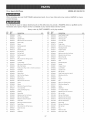
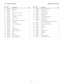
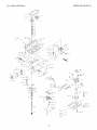
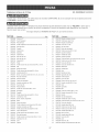
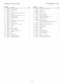
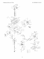
Part List ......................................................................................................................................................................... 26
EspaSol .......................................................................................................................................................................... 3!
Service mnformation ........................................................................................................................................ Back Page
ONE-YEAR FULL WARRANTY ON CRAFTSMAN TOOL
if this Craftsman tool fails due to a defect in material or workmanship within one year from the date of purchase,
CALL 1-800-4-MYoHOME _)TO ARRANGE FOR FREE REPAIR,
if this tool is used for commercial or rental purposes, this warranty will apply for only ninety days from the date of
purchase,
This warranty applies only while this tool is in the United States,
This warranty gives you specific legal rights, and you may also have other rights, which vary from state to state,
Sears, Roebuck and Co,, Dept 817WA, Hoffman Estates, IL 60179

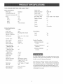
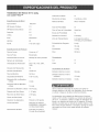
12°in. Bench Drill Press with Laser°Trac TM
Motor Specifications:
Motor type induction
Continuous duty HP 1/3
Maximum developed HP 2/3
Amps 6,5
Volts 120
Phase Single
Hertz 60
R,P,M, 1725 (no load)
Product Specifications:
Belt Type
Pulley Type
Number of Speeds
Drill Speeds
Spindle Taper
Chuck Taper
Chuck Type
Chuck capacity
Chuck to Table
dimension Min,
Chuck to Table
dimension Max,
Chuck to Base
dimension
Quill Diameter
Quill Travel
Quill Lock
Handle Operation
Motor Control
Table Size
Table Tilt
Table Movement
Table Material
V=Belt
Step
Pivoting motor mount
5
620, 1100, 1720, 2340,
3100
Jacobs 33
Jacobs 33
Keyless
1/32" =1/2"
2 _
t 4 _
18o3/4"
1-1/2"
2o3/8"
Yes
360 degree rotation
Toggle ON/OFF with
removable Key
8o5/8" wide x 10" depth
Yes
Rack and pinion
Cast Iron
Depth Stop
Depth Stop Type
Depth Scab
Column Diameter
Base Work Area
Depth of Throat
Height
Width
Depth
Weight
Yes
Quick Set
Yes
2o3/8"
8ol/2" wide x 9o3/8" depth
6"
34"
11"
21"
93 pounds
Convenience:
Light Yes
Laser Yes
Product Capacities:
Maximum diameter
in steel 3/8"
Maximum diameter in
cast iron 1/2"
Maximum diameter
in wood 3"
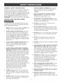
To avoid electrical shock to yourself and damage to the
drill press, use proper circuit protection, Do not expose
to rain, or use in a damp environment,
The drill press is factory wired for 120V, 60 Hz, opera=
tion, Connect to a 120V, 15 amp branch circuit and use
a 15 amp time delay fuse or circuit breaker, The electri=
cal circuit cannot have any wire size less than #14, To
avoid shock or fire, replace power cord immediately if it
is damaged in any way,

GENERAL SAFETY iNSTRUCTiONS
Operating a drill press can be dangerous if safety and
common sense are ignored, The operator must be
familiar with the operation of the tool, Read this manual
to understand this drill press, DO NOT operate this drill
press if you do not fully understand the limitations of
this tool, DO NOT modify this drill press in any way,
REMEMBER: Your personal safety is your responsibility,
BEFORE USUNG THE DF_ULLPRESS
To avoid serious injury and damage to the tool, read
and follow all of the Safety and Operating instructions
before operating the drill press,
1, READ the entire instruction Manual, LEARN how to
use the tool for its intended applications,
2,
ALWAYS WEAR EYE PROTECTION, Any power
tool can throw debris into the eyes during opera-
tions, which could cause severe and permanent
eye damage, Everyday eyeglasses are NOT safety
glasses, ALWAYS wear Safety Goggles (that
comply with ANSi standard Z87,1) when operating
power tools, Safety Goggles are available at Sears
Retail Stores,
3, ALWAYS WEAR HEARING PROTECTION, Plain
cotton is not an acceptable protective device,
Hearing equipment should comply with ANSi
$3,19 Standards,
4, ALWAYS WEAR A DUST MASK TO PREVENT
INHALING DANGEROUS DUST OR AIRBORNE
PARTICLES, including wood dust, crystalline silica
dust and asbestos dust, Direct particles away from
face and body, Always operate tool in well ventilat-
ed area and provide for proper dust removal, Use
dust collection system whenever possible,
Exposure to the dust may cause serious and per-
manent respiratory or other injury, including silicosis
(a serious lung disease), cancer, and death, Avoid
breathing the dust, and avoid prolonged contact
with dust, Allowing dust to get into your mouth or
eyes, or lay on your skin may promote absorption of
harmful material, Always use properly fitting
NIOSH/OBHA approved respiratory protection
appropriate for the dust exposure, and wash
exposed areas with soap and water,
5,
ALWAYS keep the work area clean, well lit, and
organized, DO NOT work in an environment with
floor surfaces that are slippery from debris, grease,
and wax,
6, ALWAYS unplug the tool from the electrical recep-
tacle when making adjustments, changing parts or
performing any maintenance,
7,
8,
9,
10,
11,
12,
13,
14,
15,
16,
17,
18,
19,
AVOID ACCIDENTAL STARTING, Make sure that
the power switch is in the "OFF" position before
plugging in the power cord to the electrical
receptacle,
AVOID A DANGEROUS WORKING ENVIRON-
MENT. DO NOT Use electrical tools in a damp
environment or expose them to rain.
CHILDPROOF THE WORKSHOP AREA by remov-
ing switch keys, unplugging tools from the electrical
receptacles, and using padlocks,
DO NOT use electrical tools in the presence of
flammable liquids or gasses,
DO NOT FORCE THE TOOL to perform an opera-
tion for which it was not designed, it wiii do a safer
and higher quality job by only performing operations
for which the tool was intended,
DO NOT stand on a tool, Serious injury could result
if the tool tips over or you accidentally contact the
tool,
DO NOT store anything above or near the tool
where anyone might try to stand on the tool to
reach it,
DO NOT operate tool if under the influence of drugs
or alcohol,
EACH AND EVERY TIME, CHECK FOR DAMAGED
PARTS PRIOR TO USING THE TOOL. Carefully
check all guards to see that they operate properly,
are not damaged, and perform their intended func-
tions, Check for alignment, binding or breaking of
moving parts, A guard or other part that is damaged
should be immediately repaired or replaced,
GROUND ALL TOOLS, if the tool is supplied with a
3-prong plug, it must be plugged into a 3-contact
electrical receptacle, The 3rd prong is used to
ground the tool and provide protection against
accidental electric shock, DO NOT remove the 3rd
prong, See Grounding instructions,
KEEP VISITORS AND CHILDREN AWAY from the
drill press, DO NOT permit people to be in the
immediate work area, especially when the electrical
tool is operating,
KEEP PROTECTIVE GUARDS IN PLACE AND IN
WORKING ORDER,
MAINTAIN YOUR BALANCE. DO NOT extend
yourself over the tool. Wear oil resistant rubber-
soled shoes. Keep floor clear of debris, grease, and
wax,

20. MAINTAIN TOOLS WITH CARE. Always keep tools
clean and in good working order. Keep all blades
and tool bits sharp.
21. NEVER LEAVE A RUNNING TOOL UNATTENDED,
Turn the power switch to the OFF position, DO
NOT leave the tool until it has come to a complete
stop,
22. REMOVE ALL MAINTENANCE TOOLS from the
immediate area prior to turning the tool ON.
23. SECURE ALL WORK. When it is possibb, use
damps or jigs to secure the workpbce. This is safer
than attempting to hold the workpbce with your
hands.
24. STAY ALERT, watch what you are doing, and use
common sense when operating a power tool. DO
NOT USE a tool wNe tired or under the influence
of drugs, abohol, or medication. A moment of
inattention whib operating power tools may result
in serious personal injury.
25. USE ONLY RECOMMENDED ACCESSORIES.
Use of incorrect or improper accessories could
cause serious injury to the operator and cause
damage to the tool. if in doubt, check the instruction
manual that comes with that particular accessory.
26. USE A PROPER EXTENSION CORD IN GOOD
CONDITION. When using an extension cord, be
sure to use one heavy enough to carry the current
your product will draw. Please see "MiNiMUM
RECOMMENDED GAUGE FOR EXTENSION
CORDS (AWG)" table for correct sizing of an exten-
sion cord. if in doubt, use the next heavier gauge.
27. WEAR PROPER CLOTHING. DO NOT wear loose
clothing, gloves, neckties, or jewelry. These items
can get caught in the machine during operations
and pull the operator into the moving parts. Users
must wear a protective cover on their hair, if the
hair is long, to prevent it from contacting any
moving parts.
GUIDELINES FOR EXTENSION CORDS
The smaller the gauge number, the larger diameter of
the extension cord is. if in doubt of the proper size of an
extension cord, use a shorter and thicker cord. An
undersized cord wiii cause a drop in line voltage result-
ing in a loss of power and overheating. USE ONLY A
3-WIRE EXTENSION CORD THAT HAS A 3_PRONG
GROUNDING PLUG AND A 3-POLE RECEPTACLE
THAT ACCEPTS THE TOOL'S PLUG,
If you are using an extension cord outdoors, be sure
it is marked with the suffix "W°A" ("W" in Canada) to
indicate that it is acceptable for outdoor use.
Be sure your extension cord is properly sized, and
in good electrical condition. Always replace a damaged
extension cord or have it repaired by a qualified person
before using it.
Protect your extension cords from sharp objects,
excessive heat, and damp or wet areas.
120 VOLT OPERATION ONLY
25'LONG 50' LONG 100' LONG
0 to 6 Amps
6 to 10 Amps
10 to 12 Amps
12 to 15 Amps
18 AWG
18 AWG
16 AWG
14 AWG
16 AWG
16 AWG
16 AWG
12 AWG
16 AWG
14 AWG
14 AWG
Not
recommended

THIS TOOL MUST BE GROUNDED while in use to
protect the operator from eUectric shock.
IN THE EVENT OF A MALFUNCTION OR BREAK-
DOWN, grounding provides the path of bast resistance
for eUectriccurrent and reduces the risk of eUectric
shock. This tooUis equipped with an eUectric cord that
has an equipment-grounding conductor and a ground-
ing pDg. The pUugMUST be pDgged into a matching
eUectrbaUreceptacle that is properUy installed and
grounded in accordance with ALL bcaU codes and
ordinances.
DO NOT MODIFY THE PLUG PROVIDED. if it wHUnot
fit the eUectrbaUreceptacb, have the proper eUectrbaU
receptacle installed by a qualified electrician.
IMPROPER ELECTRICAL CONNECTION of the equip°
ment-grounding conductor can result in risk of electric
shock. The conductor with the green insulation (with
or without yellow stripes) is the equipment-grounding
conductor. DO NOT connect the equipment-grounding
conductor to a live terminal if repair or replacement of
the electric cord or plug is necessary.
CHECK with a qualified electrician or service personnel
if you do not completely understand the grounding
instructions, or if you are not sure the tool is properly
grounded.
The motor supplied with your drill press is a 120 volt,
singb-phase motor. Never connect the green wire to a
live terminal.
USE ONLY A 3-WIRE EXTENSION CORD THAT HAS
A 3-PRONG GROUNDING PLUG AND A 3-POLE
RECEPTACLE THAT ACCEPTS THE TOOL'S PLUG.
REPLACE A DAMAGED OR WORN CORD IMMEDI-
ATELY.
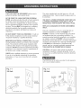
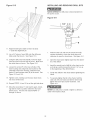
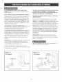
This too[ is intended for use on a circuit that has an
electrical receptacle as shown in FIGURE !-1.
FIGURE !-! shows a 3-wire electrical plug and electri-
cal receptacle that has a grounding conductor. If a
properly grounded electrical receptacle is not available,
an adapter as shown in FIGURE 1-2 can be used to
temporarily connect this plug to a 2-contact ungrounded
receptacle. The adapter has a rigid lug extending from
it that MUST be connected to a permanent earth
ground, such as a properly grounded receptacle box.
THIS ADAPTER IS PROHIBITED IN CANADA.
CAUTION: In all cases, make certain the electrical
receptacle in question is properly grounded. If you are
not sure have a certified electrician check the electrical
receptacle.
This Drill Press is for indoor use only, Do not expose to
rain or use in damp locations,
Fig. 1-1
120 Volt
grounding
conductor
3-wire power cord
3-prong
electrical
receptacle
Fig. 1-2
120 Volt
grounding
conductor
3-wire power cord
grounding
adapter lu!
0
2-prong
electrical
receptacle

SPECIFIC SAFETY iNSTRUCTiONS
The operation of any drill press can result in debris
being thrown into your eyes, which can result in severe
eye damage, ALWAYS WEAR EYE PROTECTHON, Any
power tool can throw debris during operations, which
could cause severe and permanent eye damage.
Everyday eyeglasses are NOT safety glasses. ALWAYS
wear Safety Goggles (that comply with ANSi standard
Z87.1) when operating power tools. Safety Goggles are
available at Sears Retail Stores.
Basic precautions should always be followed when
using your drill press. To reduce the risk of injury, elec-
trical shock or fire, comply with the safety rubs listed
below:
1. READ and understand the instruction manual
before operating the drill press.
2, AVOHD AWKWARD OPERATHONS AND HAND
POSHTHONS. A sudden slip could cause a serious
injury.
3. CHECK all drill bits, cutting tools, sanding drums, or
other accessories for damage before installing in
the drill press chuck. Damaged items can cause
damage to the drill press and or serious injury.
4. Before leaving the drill press, LOCK or REMOVE
the ON/OFF switch/key to prevent unauthorized
use,
5,
DO NOT install or use any drill bit that exceeds
7-inches in length or that extends 6-inches below
the chuck jaws. The drill bit can suddenly bend or
break.
6. DO NOT try to drill a workpiece that is too small to
be securely held to the table or in a vise.
7. DO NOT operate this drill press until it is assembled
and installed according to the instruction manual.
8. DO NOT leave the drill press plugged into the elec-
trical outlet. Unplug the drill press from the outlet
when not in use and before servicing, changing bits
and cleaning.
9. DO NOT USE router bits, shaper cutters, circle (fly)
cutters, rotary planers or wire wheels in this drill
press.
10. FOLLOW all electrical and safety codes, including
the National Electric Code (NEC) and the
Occupational Safety and Health Regulations
(OSHA). All electrical connections and wiring should
be made by qualified personnel only.
11, LET THE CHUCK REACH FULL SPEED before
starting drill operations.
12, MAKE SURE there are no foreign objects, nails,
stones in the workpiece,
13, NEVER PERFORM LAYOUT, ASSEMBLY OR
SETUP WORK on the table/work area when the
drill press is running,
14, NEVER START THE DRILL PRESS BEFORE
CLEANING THE TABLE OF ALL OBJECTS (tools,
scrap pieces, etc,), Debris can be thrown at high
speed,
15, NEVER START THE DRILL PRESS with the drill
bit, cutting tool, or sanding drum against the work-
piece, Loss of control of the workpiece can cause
serious injury,
16, OBTAIN ADVICE FROM YOUR SUPERVISOR,
instructor, or another qualified person if you are not
familiar with the operation of this drill press,
17, PROPERLY SUPPORT long or wide workpiece and
clamp to the table,
18, PROPERLY SECURE the drill bit, cutting tool, or
sanding drum in the chuck before operating the drill
press,
19, REPLACE a damaged cord immediately, DO NOT
use a damaged cord or plug, if the drill press is not
operating properly, or has been damaged, left out-
doors or has been in contact with water, return it to
a Sears Service Center,
20. SECURE the drill press to the floor or work bench.
Vibration can cause the drill press to slide, walk or
tip over.
21. SECURE the workpieee firmly against the table.
Do not attempt to drill a workpiece that does not
have a fiat surface against the table, or that is not
secured by a vise. Prevent the workpiece from
rotating by damping it to the table or by securing it
against the drill press column. Loss of control of
the workpieee can cause serious injury.
22. SECURELY LOCK the head and table support to
the column, and the table to the table support
before operating the drill press.
23. The drill press is designed for home use or light
commercial duty ONLY.
24, TO REDUCE THE RISK OF ELECTRICAL
SHOCK, do not use outdoors, Do not expose to
rain, Store indoors in a dry area,
25, TURN THE DRILL PRESS OFF and unplug from
power source, Wait for the drill bit, cutting tool, or
sanding drum to come to a complete STOP before
cleaning off the table/work area, removing or secur-
ing workpiece, or changing setup,
26. USE only drill bits, cutting tools, sanding drums, or
other accessories with proper shank size recom-
mended in this instruction manual. The wrong size
shank can cause damage to the drill press and/or
serious injury.

27,USEonlyasdescribedinthisinstructionmanual,
USEaccessoriesonlyrecommendedbySears,
28,USERECOMMENDEDSPEEDSforalloperations,
Otherspeedsmaycausethemachinetomalfunc°
tioncausingdamagetothedrillpressandor
seriousinjury,
29,informationregardingthesafeandproperoperation
ofthistoolisaboavailabbfromthefollowing
sources:
Power Tool institute
1300 Summer Avenue
Cbveland, OH 44115-2851
www, powertoolinstitute,org
National Safety Council
1121 Spring Lake Drive
Itasca, IL 60143-3201
American National Standards institute
25 West 43rd Street, 4th floor
New York, NY 10036
www, ansi,org
ANSi 01,1 Safety Requirements for
Woodworking Machines, and the
U,S, Department of Labor regulations
www, osha,cj__
30, SAVE THESE INSTRUCTIONS, Refer to them
frequently and use them to instruct other users,
ADDmONAL SAFETY RULES
FOR THE LASER
1, LASER LIGHT - DO NOT STARE INTO BEAM,
APERTURE, or into a reflection from a mirror-like
surface,
2,
AVOID EXPOSURE - LASER LIGHT IS EMITTED
FROM BOTH SIDES OF LASER ASSEMBLY,
Use of controls or adjustments, or performance of
procedures other than those specified herein may
result in hazardous laser light exposure,
3, DO NOT DISASSEMBLE LASER MODULE, The
laser is a CLASS 11LASER PRODUCT that can
emit laser power up to 1 mW MAX at 635 nm,
which could result in exposure with the module
disassembled, The laser unit complies with 21
CFR 1040,10 and 1040,11,
4, USE OF CONTROLS OR ADJUSTMENTS OR
PERFORMANCE OF PROCEDURES OTHER
THAN THOSE SPECIFIED HEREIN MAY RESULT
IN HAZARDOUS RADIATION EXPOSURE.
AVAILABLE ACCESSORIES
Visit your Sears Hardware Department or see the
Craftsman Power and Hand Tool Catalog for the follow-
ing accessories,
iTEM STOCK NUMBER
* Circle Cutter 25293
* Clamping Lit 26426
* 8-in, Vise 24077
* 4-in, Vise 24081
* 3-in, Vise 24071
* 21 pc, Sanding Drum Kit 25262
* 7 pc, Forstner Bit Set 25389
Sears may recommend other accessories not listed in
this manual
See your nearest Sears Hardware Department or
Craftsman Power and Hand Tool Catalog for other
accessories,
Do not use any accessory unless you have completely
read the instruction Manual for that accessory,
Use only accessories recommended for this drill press,
Using other accessories may cause serious injury and
cause damage to the drill press,

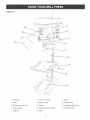
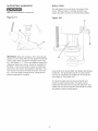
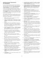
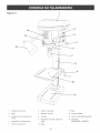
Figure 2-1 1
13
12
1, Beit cover
2, Motor
3, Beit tension Hockknob
4, Feed handies
5, QuHHHock
6, Laser (not shown)
7, Keyiess chuck
8, Column
9, TaMe raise/iower Handie
10, TaMe
11, Base
12, Flexible lamp
13, Adjustable depth stop
14, ON/OFF switch

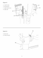
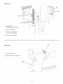
Figure 2-2
15, ON/OFF switch
16, Removable key
17, Depth scale lock nuts
18, Depth scale
Figure 2-3
19, Bevel scale
20, Table lock handle
19
10

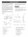
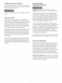
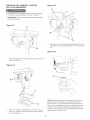
UNPACKING AND CHECKING CONTENTS
This drill press will require some amount of assembly,
Remove all of the parts from the shipping box and lay
them on a clean work surface,
Remove any protective matedab and coatings from all
of the parts and the drill press, The protective coatings
can be removed by spraying WD-40 on them and
wiping it off with a soft cloth, This may need redone
several times before all of the protective coatings are
removed compbtely, CAUTION: DO NOT use acetone,
gasoline or lacquer thinner to remove any protective
coatings on your drill press,
After cbaning, apply a good quality automotive wax to
any unpainted surfaces, Make sure to buff out the wax
before assembly,
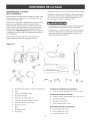
Figure 3-1 A ............/_'_.
Compare the items to Figure 3-1 below; verify that all
items are accounted for before discarding the shipping
box, If there are any missing parts, call Customer
Helpline 1°800°897°7709,
The drill press is a heavy machine, two people may
be required to unpack and lift machine,
if any parts are missing, do not attempt to plug in the
power cord and turn ON the drill press, The drill press
can only be turned ON after all the parts have been
obtained and installed correctly,
B
C
J
K
A, Drill press head and motor assembly
B, Table
C, Column, rack and ring
D, Worm gear
E, Feed handle (S)
F, Table raise/lower handle
G, Table lock handle
H, Keyless chuck
I, Base
J, Laser assembly
K, Clamp
11
Ddlt Press Hardware: (not shown)
L, Hex head cap screw M8-1,25 x 25mm (4)
Mounting Hardware: (not shown)
M, Hex head screw M8-1,25 x 125mm (2)
N, Fiat Washer M8 (2)
O, Lock Washer M8 (2)
R Hex Nut M8-1,25 (2)
Toots Included: (not shown)
Q, 2,5mm Hex wrench
R, 3mm Hex wrench
S, 4mm Hex wrench

TOOLS REQUIF{EB
The following toob are needed for assembly and align-
ment, Note: Two hex wrenches (3mm and 4mm) are
provided, The remaining tools are typbal shop toob and
are not included with your drill press,
12ram Open end wrench Hammer and block of wood
13ram Open end wrench Combination square
#2 Phillips screwdriver
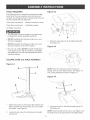
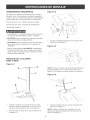
Figure 4-2
The drill press is a heavy machine; two people may
be required for certain assembly operations,
DO NOT assemble the drill press until you are sure
the tool is unplugged,
DO NOT assemble the drill press until you are sure
the power switch is in the "OFF" position,
For your own safety, DO NOT connect the drill press
to the power source until the machine is completely
assembled and you read and understand the entire
instruction Manual,
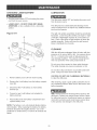
COLUMN, BASE and TABLE ASSEMBLY
J
H
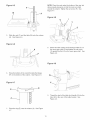
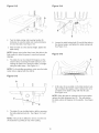
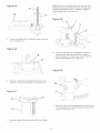
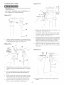
3, Place the worm gear (G) in the table bracket (H),
See Figure 4-2,
Figure 4-3
Figure 4-1
B
C
NOTE: Place the small end of the worm gear (I)
through hob (J), in the table bracket, See Figure 4-2,
The correct placement is shown in Figure 4-3,
Figure 4-4
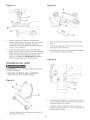
2,
Attach the column (A) to the base (B) using the four
M8x1,25x25mm hex head screws (C), two of which
are shown, See Figure 4-1,
Loosen the set screw (D) and remove the ring (E)
and rack (F),
4, insert the rack (F) in the table bracket groove (K),
See Figure 4-4,
NOTE: Place the teeth of the rack (L), see Figure 4-4 in
the teeth of the worm gear inside of the table bracket,
12

NOTE:Placetherackunderthebottomofthering,but
allowenoughclearancesothattherackcanrotate
aroundthecolumn,Tightenthesetscrew(R),See
Figure4-7,
Figure 4-8
U
I
T
5, SNde the rack (F) and the tabb (M) onto the column
(A), See Figure 4-5,
Figure 4-6
N
I
f
S
8,
Attach the tame raising and bwedng handb (S) on
the worm gear shaft (I) and tighten the set screw
(T) against the flat (U) on the worm gear shaft, See
Figure 4-8,
Figure 4-9
6,
Hace the bottom of the rack (N) inside the flange
(P) on the bottom of the column, See Figure 4-6,
Figure 4-7
E_
jR
9,
Thread the stud of the tame bck handb (V) into the
hob (W) in the rear of the tame bracket, See
Figure 4-9,
7, Place the ring (E) onto the column (A), See Figure
4-7,
13

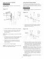
DRILL PRESS HEAD AND
MOTOR ASSEMBLY
* The drHUpress is a heavy machine; two peopb may
be required for certain assemMy operations,
* MAKE CERTAIN the drHUpress is disconnected from
the power source,
Figure 5-1
A
Figure 5-3
G
\\
\
B
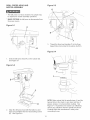
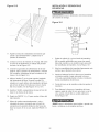
1, Seat the drHUpress head (A) on the coUumn (B),
See Figure 5-1
Figure 5-2
i !
, C
H
F
3, Thread the three feed handbs (F) in the three
tapped hobs (G) bcated in the pinion shaft (H),
Figure 5-4
2,
Align the drill press head with the table (C) and
base (D) and tighten the two head locking screws
(E), See Figure 5-2,
NOTE: Make certain that the spindle taper (I) and the
tapered hob in the chuck (J) are clean and free of
grease, lacquer, or rust preventive coatings, See
Figure 5-4 Household oven cleaner can effectively
remove any substance from the spindle and chuck,
Carefully follow the manufacturer's safety rubs
concerning its use,
14

Figure 5-5 Figure 6°2
F
D
C
4, Open the chuck jaws compbteUy, hoUdthe top collar
(K) and turn the chuck barreU(L) counter-clockwise,
Make sure the jaws are compbteUy recessed inside
the chuck, See figure 5-5,
5, Seat the chuck onto the drHUpress spindb as far as
it wHUgo, Carefully drive the chuck onto the spindb
by pUacinga wooden bbck (M) under the chuck (N)
and tap the Mock up with a hammer (O),IMPOR-
TANT: DO NOT tap the chuck directly with a metaU
hammer,
LASER ASSEMBLY
2, Remove battery cover (C) from ]aser housing,
3, Connect a 9-voUtbattery (D) (not incUuded) to
battery termina] (E),
4, PUacebattery into battery compartment (F) and
repUace battery cover,
Figure 6-3
,, MAKE CERTAIN the drHUpress is disconnected from
the power source,
LASER LIGHT o DO NOT STARE INTO BEAM,
APERTURE, or into a reflection from a mirror-like
surface,
Figure 6-1
Place clamp (A) through openings (B) in laser
housing,
5,
6,
15
Place laser around column (G) and against the
head casting (H) and fasten the clamp securely at
the column,
Make sure laser housing is positioned so that one
laser is to each side of the head casting,

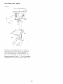
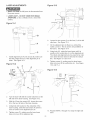
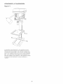
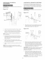
FASTENING DRILL PRESS
Figure 7-1
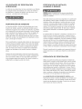
The drill press should be fastened to a supporting
surface, Secure the machine base to the supporting
surface with an M8x1,25x125mm carriage head
screw, 8,5ram fiat washer, 8,Smm lock washer, and
M8x1,25 hex nut through the two hobs (A) located in
the machine base, See Figure 7:1, This win help reduce
the tendency of the drill press to tip over, slide, or walk,
16

* DONOTexposetheddHpresstorainoroperatethe
indampbcations.
* MAKESUREaHpartshavebeenassembbdcorrectly
andareinworkingorder.
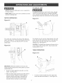
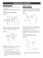
SWITCH OPERATION
Figure 8-1
FLEXIBLE LAMP
To reduce the risk of fire, use 40 watt or bss, 120 voUt,
reflector track-type Hght buUb(not supplied). DO NOT
use a standard househoUd Hght buUb.The reflector track-
type Hght buUbshouUd not extend bebw the Uampshade.
Figure 9-1
B
The switch (A) is bcated on the front of the ddHpress
head. See Figure 8-1. To turn the ddH press ON, move
the switch up. To turn the ddH press OFF, move the
switch down.
Figure 8-2
B
\ \\\
\\\
\ \\
\
IMPORTANT: When the machine is not in use, the
switch shouUdbe bcked in the OFF position to prevent
unauthorized use.
1. Grasp the switch toggle (B) and pull it out of the
switch. See Figure 8-2.
2. With the switch toggle removed, the switch will not
operate. However, should the switch toggle be
removed while the drill press is operating, the
switch can still be turned OFF, but cannot be
restarted without inserting the switch toggle.
The flexible lamp (A) operates independently of the drill
press, but uses the same power cord, To turn the lamp
ON and OFF, rotate the switch (B) in the clockwise
direction only, See Figure 9-1,
CAUTION: The flexible lamp housing will remain hot for
a few minutes after turning it OFF, Avoid contact with
housing until it is cool,
TABLE OPERATION
Figure 10-1
C
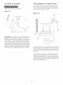
1, To raise or lower the table (A) on the column (B),
loosen the table lock handle (C), See Figure 10-1,
17

Figure 10-2 Figure 10-4
D
2, Turn the table raising and lowering handle (D)
clockwise to raise the table and counterclockwise
to lower the table, See Figure 10-2,
3, After the table is at the desired height, tighten the
table clamp,
NOTE: Always raise (rather than lower) the table to the
final position to allow the gears to mesh and prevent
slippage,
4,
The table (A) can be rotated 360 degrees on the
column (B) by loosening the table clamp (C) and
rotating the table to the desired position, and tight-
ening the table clamp, See Figure 10-1,
NOTE: For thru-drilling operations, make sure the table
center hob is aligned with the drill bit,
Figure 10-3
G
E
6, Loosen the table locking bolt (G) and tilt the table to
the desired angle, and tighten the table locking bolt,
See Figure 10-4,
Figure 10-5
H
100 0 100 200
7,
A tilt scab (H) is provided on the table bracket cast-
ing to indicate the degree of tilt, A witness line (I) is
provided on the table to align with the tilt scab,
See Figure 10-5,
NOTE: When the table is returned to the level position,
replace the table alignment pin (E), This will position
the table surface 90 degrees to the spindle, See Figure
10-3,
5, The table (A) can be tilted right or left by removing
the table alignment pin (E), See Figure 10-3 and
10-4,
NOTE: if the pin (E) is difficult to remove, turn the nut
(F) clockwise to pull the pin out of the casting,
18

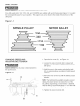
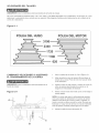
DRULL SPEEDS
MAKE CERTAIN the drill press is disconnected from the power source,
Five drill speeds (620, 1100, 1720, 2340, and 3100 RPM) are available with your drill press, See Figure 11-1 to select
the correct spindle speed for your operation, This diagram can also be found on the inside of the belt cover of the
drill press,
Figure 11-1
SPINDLE PULLEY MOTOR PULLEY
CHANGUNG SPEEDS AND
ADJUSTING BELT TENSUON
MAKE CERTAIN the ddH press is disconnected from
the power source,
Figure 12-1
D
\\
B
1, Open the beUtcover (A), See Figure 12-1,
2, Loosen the tension Uockknob (B) to reUeasebeUt
tension, Pivot the motor (C) toward the front of the
ddH press,
3, Hold the motor in this position and pUacethe beUt
(D) on seUected pulleys according to the ddH speed
diagram,
4, Move the motor to the rear until the beUthas proper
tension,
NOTE: The beUtshouUd be just tight enough to prevent
slipping, Excessive tension wHUreduce the Hfeof the
beUt,pulleys and bearings, Correct tension is obtained
when the belt (D) can be flexed about 1" out of line mid-
way between the pulleys using light finger pressure,
5, Tighten the tension lock knob (B),
19

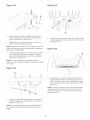
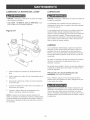
DRULLING HOLES TO DEPTH
MAKE CERTAIN the drill press is disconnected from
the power source.
ADJUSTING RETURN SPRUNG
The ddH chuck wHUautomatically return sUowUyto its
upper position when the handUeis reUeased,The return
spring was propedy adjusted at the factory, However, to
adjust, if necessary:
Figure 13-1
C
MAKE CERTAIN the ddH press is disconnected from
the power source.
Figure 14-1 D
C
0
1. Loosen both nuts (A) and (B). Make sure that the
spring housing (C) remains engaged with head
casting (D). See Figure 14-1.
1. Unsertthe ddH bit into the keyUesschuck and tighten.
2. Hace the workpiece on the ddH press tame. Raise
the drHUpress tame until the workpiece is 1/8-in
from the drill bit.
NOTE: Make sure the workpiece is secured to the table
properly.
3. Turn the two lock nuts (A) on the thread depth scale
(B) until the bottom lock nut is aligned with the
dimension you want to drill on the scale (C).
4. Tighten the top lock nut against the bottom nut.
This will keep the lock nuts from moving during
drilling operations.
5. Drill a test hole to check the depth.
NOTE: For thruodrilling operations, make sure the table
center hole is aligned with the drill bit.
Figure 14-2
C E
2O
2, While firmly holding the spring housing (C) pull the
spring housing out and rotate it (counteroclockwise
to increase or clockwise to decrease the spring ten°
sion) until the boss (E) is engaged with the next
notch (F) on the spring housing, See Figure 14-2,
IMPORTANT: Because the return spring is under tension,
it will want to unwind (clockwise), Make sure you have
a firm hold of the spring housing before pulling it out,
3, Turn the nut (B) until it contacts the spring housing
(C), then back the nut (B) out 1/4 turn from the
spring housing (C), Tighten the nut (A) against the
nut (B) to lock the nuts from turning, See Figure
14-1 and 14-2.
IMPORTANT: The inside nut should not contact spring
housing when tightened.
Page is loading ...
Page is loading ...
Page is loading ...
Page is loading ...
Page is loading ...
Page is loading ...
Page is loading ...
Page is loading ...
Page is loading ...
Page is loading ...
Page is loading ...
Page is loading ...
Page is loading ...
Page is loading ...
Page is loading ...
Page is loading ...
Page is loading ...
Page is loading ...
Page is loading ...
Page is loading ...
Page is loading ...
Page is loading ...
Page is loading ...
Page is loading ...
Page is loading ...
Page is loading ...
Page is loading ...
Page is loading ...
Page is loading ...
Page is loading ...
Page is loading ...
Page is loading ...
Page is loading ...
Page is loading ...
Page is loading ...
Page is loading ...
Page is loading ...
Page is loading ...
Page is loading ...
Page is loading ...
-
 1
1
-
 2
2
-
 3
3
-
 4
4
-
 5
5
-
 6
6
-
 7
7
-
 8
8
-
 9
9
-
 10
10
-
 11
11
-
 12
12
-
 13
13
-
 14
14
-
 15
15
-
 16
16
-
 17
17
-
 18
18
-
 19
19
-
 20
20
-
 21
21
-
 22
22
-
 23
23
-
 24
24
-
 25
25
-
 26
26
-
 27
27
-
 28
28
-
 29
29
-
 30
30
-
 31
31
-
 32
32
-
 33
33
-
 34
34
-
 35
35
-
 36
36
-
 37
37
-
 38
38
-
 39
39
-
 40
40
-
 41
41
-
 42
42
-
 43
43
-
 44
44
-
 45
45
-
 46
46
-
 47
47
-
 48
48
-
 49
49
-
 50
50
-
 51
51
-
 52
52
-
 53
53
-
 54
54
-
 55
55
-
 56
56
-
 57
57
-
 58
58
-
 59
59
-
 60
60


Craftsman 152219110 Owner's manual
- Category
- Power tools
- Type
- Owner's manual
- This manual is also suitable for
Ask a question and I''ll find the answer in the document
Finding information in a document is now easier with AI
in other languages
Related papers
-
Craftsman 351.229000 Owner's manual
-
-
-
-
-
Sears Drill 113.21371 User manual
-
-
-
-
Other documents
-
Skil 3320 User manual
-
-
 Ironton Benchtop Drill Press Owner's manual
-
Genesis GDP805P User guide
-
 Steel City 20530 User manual
-
Genesis GDP500 User guide
-
Rockwell ShopSeries RK7032 User manual
-
-
-
Porter Cable PCB660DP User manual

