Page is loading ...

Meyer Products reserves the right, under its continuing product improvement program, to change construction or design details,
specifications and prices without notice or without incurring any obligation.
PARTS & INSTALLATION INSTRUCTIONS
MEYER MINI SPREADER
Form No.1-809 R4
May 2010
© 2010 Printed in the U.S.A.
18513 Euclid Ave. • Cleveland, Ohio 44112-1084
Phone 486-1313 (Area Code 216)
email•[email protected]
Meyer Products assumes no responsibility for installations not made in accordance with these instructions.
INDEX
INSTALLATION INSTRUCTIONS .......................................... PAGE 1
A. INSTALLATION OF HOPPER ...................................... PAGE 1-2
B. ELECTRICAL INSTALLATION .................................... PAGE 3-4
C. OPERATION OF MATE ............................................... PAGE 1
D. MAINTENANCE INSTRUCTIONS ............................... PAGE 1
WARRANTY STATEMENT ..................................................... PAGE 4
MATE

INSTALLATION INSTRUCTIONS
CAUTION: Always disconnect battery before beginning
installation.
NOTE: For the best installation, we recommend that the vehicle
be equipped with a step bumper. If not available, modifications
to rear of vehicle frame such as adding a trailer hitch may be
required so as to provide a lower support for the Spreader.
Relocate license plate holder and lights if blocked by any
part of the Spreader. During installation where the spreader
may touch metal, a gasket should be used to help prevent any
possible paint damage to the vehicle.
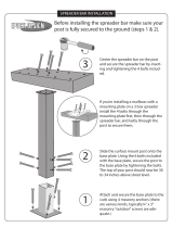
A. Installation of hopper
1. Open the cover plate (12) on the rear of the hopper
by removing 1/4-20 x 3/8 Bolts (27) and flatwashers
(26). Plug one end of the 20’ vibrator cord (3a) into
the vibrator. Snake the other end through the 1”
hole on the bottom of the hopper (1). Reattach the
rear cover plate (12).
2. Loosen both 3/8-16 x 7/8 Bolts (19), so as the Post-to-
Bumper (4) is free to slide along the bottom of the
hopper (1) in the direction of the slots.
Note: The post to bumper (4) is reversible to fit a wide
range of vehicles.
3. Open the vehicle tailgate. Place the bracket of the
strapping section with the ratchet (37D) over the striker
pin on the driver’s side of the tailgate opening. Place
the bracket of the remaining strap (37A) over the
opposite striker pin on the passenger side. Securely
close the tailgate, taking care to make sure both
brackets are positioned between the truck wall and the
side of the tailgate. Vehicles with latch type tailgates
must use Latch Kit 38043 (38) reference SB 196.
Note: if the vehicles step bumper currently has a ball hitch
mounted in the 3/4” center hole, it will need to be removed
before proceeding.
4. Place the hopper (1) onto the bumper of the vehicle,
while inserting the Post-to-Bumper (4) through the ball
hitch hole in the step bumper. Note: If Post (4) interferes
with vehicle receiver hitch, the bumper post (4) may be
trimmed to avoid contact with the hitch. While holding
the hopper on the bumper, bring both strap ends
around the front of the hopper, making sure both straps
are run underneath the handle – strap guide (10). Insert
the free end of the passenger side strap (A) into the
ratchet and through the slot in the shaft. Pull enough of
the strap through the slot so the ratchet makes contact
with the hopper. Place the excess strap over itself, and
operate the handle of the strap, snugly tightening the
unit up against the tailgate.
5. Tighten the 3/8-16 x 7/8 Bolts (19) to the specified torque.
Insert the lynch pin through a convenient hole in the
post (4), below the bumper.
6. Securely tighten the ratchet, making sure the strap
has not become twisted. The hopper should now be
held securely on the bumper, up tight against the face
of the tailgate. There should be no movement of the
hopper.
Caution: The ratchet should be tightened before each use.
The strap should be inspected for tears before each use. If
strap is torn or damaged it must be replaced!
Note: To remove the spreader, pull the tab (B) sideways, located
on front mid section of the ratchet. While holding the tab (B) in
the unlocked position pull the lever handle fully open. While
supporting the spreader, push the release tab (C) to release
tension, remove strap.
B. ELECTRICAL INSTALLATION. Refer to Page 3.
C. Operation of Mate
Due to the rate at which materials absorb moisture differently,
some materials may not perform as desired. Therefore, the
substitution of an alternate material may be necessary for
optimum performance of the spreader.
1. Adjust the flow control (31) of the auger assembly (28)
to the appropriate height for the material being spread.
2. Fill Hopper with the desired free flowing material
(#1 Rock Salt, Calcium Chloride, Sand or Seed)
When spreading sand the vibrator must be turned on. The vibrator
may also be helpful when spreading other free flowing materials.
CAUTION: When filling hopper, make certain there are no large
objects contained in the material, which could cause the auger to
bind and stop operation of the spreader motor. If this should
happen, the circuit breaker becomes overloaded and will
automatically break the circuit. Allow the motor to cool and clear
the auger before pushing the reset button.
Note: Material should never be left in the hopper for extended
periods of time when the spreader is idle. Clogging may
occur.
D. Maintenance Instructions:
Maintenance requirements for the spreader during the winter
season are relatively simple. Periodically inspect for loose
bolts and nuts. Inspect for improper ground, broken wires,
frayed or cracked wire insulation. Inspect strap for tears.
Replace as necessary. To keep maintenance to a minimum,
the following cautions are suggested:
1. Do not attempt to clear auger or spinner or to perform
any other maintenance or repair work on this spreader
unless the ignition switch is in the “OFF” position.
2. Spreading material must be loose and free from lumps
and foreign objects.
3. Empty hopper after each use and hose the spreader
off.
4. When the spreader is no longer being used remove it
from the tailgate. Remove any rust and corrosion from
the metal parts, them prime the paint. It is
recommended to detach the harness (40) to prevent
activation when not required. Store spreader in a suitable
location and attach dummy plug to socket to protect from
corrosion. Apply lubricant to the sprockets of the ratchet.
-1-

Items No. 1 through 36 are pre-assembled and shown in the exploded view for parts identification only.
FIGURE 1
* Items are packed in 38009 Misc. Parts Carton
Parts indented are included in the carton, bag or assembly under which they are indented.Check contents against the parts
list to determine all are correct and included, and also to familiarize yourself with them.
-2-
During installation where the spreader may touch metal, a gasket
should be used to help prevent any possible paint damage to the vehicle.
38
Make certain that the mounting strap is not
against anything sharp with tailgate closed.
SEE SB 196
29
30
31
32
33
34
35
36
A
D
C
B
51
13
1
4
5
7
8
9
10
13
14
15
16
17
18
19
20
21
22
11
15
17
18
19
20
21
24
28
19
2
12
23
26
27
37
D
A
17
6
PARTS LIST
Item Part No. Qty. Description
38000 1 MATE SPREADER COMPLETE
38080 1 • Spreader Assembly
1 38083 1 •• Double Wall Hopper
38050 1 •• Mate Vibrator Kit
2 38070 1 ••• Vibrator
3 * 38051 1 ••• 20’ Vibrator Wire
3A 38056 1 ••• 36” Vibrator Wire Extension
* 38052 1 ••• Vibrator Parts Bag
4 38006 1 •• Post To Bumper
5 38091 1 •• Top Cover With Latches
6 36543 3 •• Latch Keeper
7 38003 1 •• Motor Plate
8 36402 1 •• Motor
9 38081 1 •• Motor Shroud
10 38046 2 •• Handle And Srap Guide
11 38001 1 •• Spinner Band
12 38008 1 •• Cover Plate
13 22387 1 •• 38000 Safety Decal
14 20029 4 •• Bolt H 5/16-18 x 1-1/2" Gr.2
15 20352 4 •• Washer 5/16
16 20313 4 •• Locknut 5/16-18
17 22230 11 •• 3/8 Flatwasher
18 22379 10 •• 3/8 Lockwasher
19 22383 7 •• Bolt H 3/8-16 x 7/8”
20 22381 2 •• 1/2 Flatwasher
21 21380 2 •• 1/2 Lockwasher
22 22386 2 •• Bolt 1/2-13 x 1-1/4”
23 22384 4 •• Bolt H 3/8-16 x 1-3/4”
24 22382 4 •• 3/8-16 Hex Nut
25 36241 1 •• Plug Assembly Motor
26 22248 2 •• 1/4” Flatwasher
27 22393 2 •• Machine Screw1/4-20 x 3/8”
28 38040 1 •• Spinner - Auger Assembly
29 38035 1 ••• Auger Weldment
30 36152 1 ••• Spinner Hub Weldment
31 38037 1 ••• Flow Control
32 38002 1 ••• Spinner Plate (Poly)
33 20006 3 ••• Bolt H 1/4-20 x 1-1/4" Gr. 2
34 20303 3 ••• Locknut 1/4 Esna
35 21834 1 ••• Set Screw 3/8-24 x 3/8”
36* 22399 1 ••• Wire Lynch Pin 1/4 x 1-3/4”
37* 38044 1 • Strap Assembly
38 38043 1 • Latch Kit - Optional
39 22800 1 • Speed Control Assembly
40 34106 1 • Harness

B. ELECTRICAL INSTALLATION. Refer to Figure 2.
If routing wires underbody to the rear of the chassis, it is
recommended to route the wire to the inside of vehicle
frame rail. Secure the wires to the frame or OEM harness
with appropriate strapping or fasteners.
CAUTION: Some vehicles are designed to operate with
exhaust temperatures as high as 1800° F. This can easily
damage any wires which are routed too closely or allowed
to come in contact with any portion of the exhaust system.
Be certain all wires are securely installed away from the
exhaust system.
1.) Locate the wire harness and begin to route it from the rear
of the vehicle to the front. The molded rubber plug indicates
the rear of the harness, closest to the spreader. Use frame
holes and frame supports as lashing points. Do not attach
to fuel or brake lines. Avoid wire-runs along exhaust system
or hot engine parts. Melting damage to the harness can
occur in the proximity of extreme heat.
2.) Mount the rubber plug under the rear bumper.
Position this plug toward the center of the vehicle.
3.) Place the Harness portion that connects to the
battery along the firewall and fender well, but do not con-
nect yet.
4.) Drill a 1" diameter hole through the firewall. This hole will be
used to route the controller portion of the harness into the
vehicle. Before drilling always check to see what is on the
other side.
5.) Push the controller portion of harness through the hole in
the firewall that was previously drilled. NOTE: The control-
ler end will have 2 plugs on it, but only 1 plug can pass
through the firewall at a time.
6.) Move to engine compartment. Connect power leads to bat-
tery: RED WIRE (+) positive, BLACK WIRE (-) negative.
Coat the connections with dielectric grease to prevent cor-
rosion and build up. Check harness marked ‘battery’ for
voltage by temporarily removing the red tape affixed to it.
7.) Connect the blue wire from pigtail to brake light. Connect
white wire from pigtail to optional vibrator harness if equipped.
Connect red wire on pigtail to a 12 volt keyed accessory.
Connect black ground wire to ground. Connect white jumper
wire to the back of the controller marked motor white wire.
Connect red jumper wire to the back of the controller marked
battery red wire wire. The two red wires from the main con-
nector can now be connected to the two jumper wires.
(Note: wires will only connect one way) ANY ATTEMPT TO
JOIN THE CONNECTORS IMPROPERLY, FOR EXAMPLE
MALE TO MALE, COULD SHORT OUT THE CONTROL-
LER.
Misconnection resulting in a damaged controller is not
covered by warranty.
8.) Select a suitable location to mount the controller. After mount-
ing verify that the power switch is in the off position.
9.) Coil excess wire and use wire ties to secure it to a safe
location.
10.) Mate the plug coming from the spreader unit to the plug
previously installed under the rear bumper.
11.) Make sure that feed screw/spinner area of the spreader is
clear of obstructions. Turn power on at the controller and
verify that the spreader is operating in all modes. Looking
down on the impeller from the rear of the vehicle, determine
that the impeller is turning counter-clockwise. Unit may now
be operated.
Failure to follow these precautions could cause the red (output) wire
from the Speed Control to make contact with ground, causing the
transistor to burn up. Any grounding or shorting of the red (output)
wire which results in a burned transistor is not covered by warranty.
CAUTION
READ THIS ! . . Serious damage to Speed Control will
result if the following precautions are not followed:
1. Do not install Speed Control until all other wiring is
installed and Motor is test-run.
2. Be certain to connect red wire to (+) terminal of
Motor. Connecting to (-) terminal will burn up Speed
Control Tape this (+) connection so it cannot
accidentally be grounded.
3. After wires are in place, but before connecting Speed
Control, connect a jumper wire from the red wire #48
to the red wire #46. The motor should run, indicating
proper grounding and wire installation. Remove
jumper wire.
4. After the Motor has successfully been test run, the
Speed Control can be installed. Do not allow the
red wire from the control to accidentally contact any
grounded object, including the control case itself.
-3-

ELECTRICAL INSTALLATION
SPEED CONTROLLER 22800
with VIBRATOR
FIGURE 2
-4-
38056
36” Vibrator Wire Extension
40
39
Red
Red
Black
To
Battery
To
Speed
Control
To
Spreader
Motor
Blue
White
Ground
Red
White
Red
Pigtail
Mounting
Bracket
Red
ONE YEAR WARRANTY
ONE YEAR WARRANTY
Meyer Products and Diamond Equipment promises to the consumer to repair, or at our option to replace any part of
this Meyer Spreader, accessory (other than noted below) except expendable parts such as pins, Spreader fins,and
other normal wear items, which proves to be defective in workmanship or material under normal use for a period of
one year from the date of delivery to the original purchaser. During this one year, Meyer Products and Diamond
Equipment will provide, through its Distributor / Sub-Distributor network, all labor or parts necessary to correct such
defects free of charge. Faulty parts will be repaired or replaced by the Distributor / Sub-Distributor where that
particular piece of equipment was purchased. Any cost incurred in returning the product to the Distributor / Sub-
Distributor is the responsibility of the consumer.
EXCLUSIONS
IN NO EVENT SHALL MEYER PRODUCTS OR DIAMOND EQUIPMENT BE LIABLE FOR SPECIAL, INCIDENTAL OR
CONSEQUENTIAL DAMAGES OR FOR DAMAGES RESULTING FROM LACK OF NECESSARY MAINTENANCE, FROM
MISUSE, ABUSE, ACTS OF GOD, ALTERATION OF ANY PRODUCT, OR FROM USE OF PARTS OR HYDRAULIC
FLUID NOT SUPPLIED BY MEYER PRODUCTS OR DIAMOND EQUIPMENT. USE OF THE MEYER SPREADER FOR
ANY PURPOSE OTHER THAN SPREADING MATERIALS AS INTENDED BY MEYER PRODUCTS AND DIAMOND
EQUIPMENT, IS ONE EXAMPLE OF AN ABUSE AND MISUSE OF THE PRODUCT.
WARRANTY SERVICE
In order to obtain service under this warranty, the consumer must return this product to the Distributor / Sub-Distributor
from whom the product was purchased or to any authorized Meyer Products or Diamond Equipment Distributor / Sub-
Distributor, transportation and freight charges prepaid. Only Meyer Products or Diamond Equipment Distributors /
Sub-Distributors are authorized to perform the obligations under these warranties. For the address and telephone
number of the Distributor / Sub-Distributor nearest you, check the telephone directory or you may write to the
warrantor at the address below.
GENERAL
It is the responsibility of the consumer to establish the warranty period by verifying the original delivery date. A bill of
sale, canceled check or some other appropriate payment record may be kept for that purpose. For this warranty to
be effective, the consumer must complete and return the attached Warranty Registration Card immediately upon
reciept of this Meyer Products Equipment. No person is authorized to change this warranty or to create any warranty
other than that set forth herein. This warranty gives you specific legal rights and you may also have other rights which
vary from state to state. Logon to www.meyerproducts.com to register for your warranty

PARTS & INSTALLATION INSTRUCTIONS
MEYER MINI SPREADER
MATE
© 2010 Printed in the U.S.A.
18513 Euclid Ave. • Cleveland, Ohio 44112-1084
Phone 486-1313 (Area Code 216)
email•[email protected]
/