Page is loading ...

5211.7-051518
The specifications of this product may vary from this photo and are subject to change without notice.
For more brand information, please visit www.IRONMAN.com
IRONMAN
®
and the "M-DOT" logo are registered trademarks of World Triathlon Corporation Official Product of the IRONMAN
®
TRIATHLON.
Used here by permission.


1
TABLE OF CONTENTS
SERVICE-------------------------------------------------------------------------------------------------------------- 2
IMPORTANT SAFETY GUIDELINES--------------------------------------------------------------------------- 3
LABEL PLACEMENT----------------------------------------------------------------------------------------------- 6
OVERVIEW DRAWING-------------------------------------------------------------------------------------------- 7
HARDWARE PACK------------------------------------------------------------------------------------------------ 8
PARTS LIST---------------------------------------------------------------------------------------------------------- 9
ASSEMBLY----------------------------------------------------------------------------------------------------------- 10
SUPPLEMENTAL INSTRUCTION FOR CONNECTING CABLES------------------------------------- 17
ROUTING THE WIRE---------------------------------------------------------------------------------------------- 18
SAFETY OPERATION INSTRUCTION------------------------------------------------------------------------ 20
STORAGE------------------------------------------------------------------------------------------------------------ 25
REMOECONTROL & CONTROLLER OPERATION------------------------------------------------------- 26
WARRANTY---------------------------------------------------------------------------------------------------------- 27
PARTS REQUEST FORM---------------------------------------------------------------------------------------- 28

2
SERVICE
IMPORTANT: FOR NORTH AMERICA ONLY
For damaged or defective product, questions, replacement parts or any other service
support, please contact our customer service department by the below methods:
For The Best Service, please Email:
service@paradigmhw.com
Response Time: 1-2 Business Days
Emailing us with the information above will be the best method to receive a response
during peak business hours
Website:
www.paradigmhw.com
Toll-Free:
1-844-641-7922
(8:00 AM - 5:00 PM Pacific Standard Time, Monday thru Friday)
Response time may vary via calling
Please have the following information ready when requesting for service:
Your name
Phone number
Model number
Serial number
Part number
Proof of Purchase
For damaged or defective product please contact our customer service before returning
to the store.
Paradigm Health & Wellness, Inc.
1189 Jellick Ave.
City of Industry, CA 91748, USA

3
IMPORTANT SAFETY GUIDELINES

4
IMPORTANT SAFETY GUIDELINES
Read all instructions before using the Inversion Table. When using an Inversion table,
basic precautions should always be followed, including the following:
WARNING - To reduce the risk of injury to persons:
1. Make sure your equipment is correctly assembled before you use it.
2. Be sure all screws, nuts, and bolts are tightened prior to use.
3. The equipment weighs more than 44lbs / 20kgs and should be assembled and moved by two or
more people.
4. Only one person should use the equipment at a time.
5. Never operate this Equipment if it is damaged, If it is not working properly, has been dropped, or
damaged. If a problem is encountered contact Customer Service before using the equipment again.
6. Always use this equipment on a clear and level surface.
7. For household use only.
8. Do not use outdoors or near water.
9. Use the inversion table only for its intended use as described in this manual. Do not use attachments
not recommended by the manufacturer.
10. Do not wear loose clothing when using the equipment.
11. Keep all hands and feet away from any moving parts.
12. Never drop or insert any object into any opening.
13. Always wear shoes when using the inversion table.
14. Close supervision is necessary when the inversion table is used near children, or by or near invalids
or disabled persons.
15. Listen to your body. It is recommended that you rotate up and down slowly. Dizziness might occur if
you come up too fast.
16. If at any time you feel faint, light-headed, or dizziness while operating the equipment, stop exercising
immediately. You should also stop exercising if you are experiencing pain or any discomfort.
17. Wait 2 hours after eating before using the inversion table. If you start feeling nauseous, return to the
upright position slowly.
18. For any problems contact customer service. Servicing should be performed by an authorized service
representative. Our contact number is on the service page.
19. CABLE STORAGE: When not in use, wind the cable around the anchors on the rear right
frame as illustrated. Do not lay it on the ground to avoid cable damage.
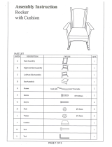
20. THE DIMENSION OF HEATING PAD:
There is a heating pad inside the foam bed. The heating pad is
23.62” (length) x 11.81” ( width) , or 600mm (length) x 300mm
(width) in dimension. The heating area is illustrated as below:

5
IMPORTANT SAFETY GUIDELINES
21. Warning: - Risk of Personal Injury - Consult with your personal physician to see if inversion
equipment is appropriate for you. This is especially important for people with pre-existing health
problems. Do not use this equipment without your physician's approval.
22. Warning: - Risk of Personal Injury – Do not allow children to use this machine.
23. Warning: - Risk of Personal Injury - Keep children under the age of 13 away from the machine
while in use.
24. Warning: - Risk of Personal Injury – Keep body parts, hair, loose clothing, and jewelry
clear of all moving parts.
25. Warning: - Risk of Personal Injury - Tilt-back slowly when inverting. Failure to comply could
result in serious bodily injury.
26. Warning: - Risk of Personal Injury - Do not attempt to service the unit yourself. Discontinue
use and contact customer service.
27. Warning: - To Reduce The Risk Of Personal Injury - Read And Understand All Read The
Instructions Before Using The Inversion Table.
Do not use this equipment if you have any of the following conditions or ailments:
Pregnancy
Extreme obesity
Middle ear infection
Hiatus hernia or Ventral hernia
Glaucoma, retinal detachment or conjunctivitis
Use of anticoagulants including Aspirin in high doses.
Spinal injury, Cerebral Sclerosis, or acutely swollen joints
Heart or circulatory disorders for which you are being treated
High blood pressure, Hypertension, Recent stroke or Transient Ischemic attack
Bone weaknesses including Osteoporosis, Unhealed fractures, Modular pins, or surgically implanted
orthopedic supports.
Do not exceed the maximum rated weight (load) and maximum
rated user height:
The Maximum Weight Capacity for this product is 275lbs/125kgs.
Retain this owner’s manual and keep the original purchase receipt for future
reference.
SAVE THESE GUIDELINES

6
LABEL PLACEMENTS

7
OVERVIEW DRAWING

8
HARDWARE & TOOLS PACK

9
PART LIST
No.
Description
Qty
No.
Description
Qty
1
Front U-Frame
1
33
Loop Strap
1
2
Rear U-Frame
1
34
Strap Lock
1
3
Adjustable Boom
1
35
"T" Type Spring Knob
1
4
Bed Frame
1
36
Rubber Rear Heel Holder
2
5
Pivot Arm
2
37
Protective Cover
2
6
Adjustable Instep Frame
1
38
Hex Head Bolt M8x23
2
7
Steel Heel Holder Bracket
2
39
Hex Head Bolt M8x50
2
8
Folding Arm
2
40
Square End Cap (□38)
2
9
Rod
1
41
Height Scale
1
10
Bolt M8x23
2
42
Nut Cap Øx27xØ13.5
2
11
Hex Head Bolt M6x47
2
43
Pivot Arm Ring
2
12
Phillips Bolt M6x30
4
44
Rod Cap
2
13
Washer Ø20xØ8.5x1.5
20
45
Spring Latch
1
14
Round Plate
1
46
Plastic Bushing
1
15
Lock Nut M8
8
47
Phillips Bolt M6x20
4
16
Lock Nut M6
6
48
Left Front Foot Cap
1
17
Foam Grip
2
49
Right Front Foot Cap
1
18
Ball Spring Knob
1
50
Left Rear Foot Cap
1
19
Safety Hook
2
51
Right Rear Foot Cap
1
20
Rubber Pad
1
52
Hex Head Bolt M8x45
4
21
Oval End Cap (20x40)
2
53
Hex Head Bolt M8x38
2
22
Spring
1
54
Controller with Power Cord
1
23
Square End Cap (□33.4)
1
55
Anchor
2
24
Round End Cap
2
56
Washer Ø12xØ6.5x1.0
4
25
Far Infrared Foam Bed
1
57
Remote Control
1
26
Lower Bed Frame Bushing
2
58
Velcro Strap
2
27
Washer Ø16xØ6.5x1.0
8
59
End Cap (□25x50mm)
4
28
Upper Bed Frame Bushing
1
60
Foot Bar
1
29
Handlebar
2
61
Foot Bar End Cap (20x60)
2
30
Knob
1
62
Screw ST3.5x15
2
31
Front Heel Holder
2
63
Screw ST4.0x20
2
32
Nylon Strap
1

10
ASSEMBLY
Step 1
1A. Stand up the base of the machine by separating the
frames. Pull the Front and Rear U-Frames (1, 2) as far
apart from each other as possible. Then push down on
the middle of the two Folding Arms (8) until they are fully
locked down.
1B. Attach Left/Right Front Foot Caps (48, 49) onto the
bottom of the Front U-Frame (1) with two Phillips Bolts
(47) and two Washers (56). Attach Left/Right Rear Foot
Caps (50, 51) onto the bottom of the Rear U-Frame (2)
with two Phillips Bolts (47) and two Washers (56).
Tighten bolts with the Phillips Screwdriver provided.
Hardware:
․․․․․․․․․․․․․․․․․․․․․․․․․․․․․․․․․․․․․․․․․․․․․․․․․․․
Step 2
2A. Install two Nut Caps (42) onto M8 Lock Nuts (15).
2B. Slide the Protective Covers (37) on to each side of the
base as shown, and pull down on the covers until the bottom
of the covers are slightly lower than the Folding Arms (8).
Use the Velcro straps on the bottom of the covers to secure
the covers to the folding arms.
2C. When the covers are assembled correctly, the folding
arms should be fully covered by the protective covers.
Hardware:
(42) Nut Cap Ø27xØ13.5
2 PCS
(56)Washers
4PCS
(47) Phillips Bolts
4PCS
Tool:
Phillips Screwdriver
1PC

11
ASSEMBLY
Step 3
3A. Slide the bottom of the Pivot Arms (5) into the
brackets, located at each side of the Bed Frame (4),
align to the desired hole on the arm with the
peg on the bracket.
3B. Insert the peg into the hole to lock the pivot arm in
place. It is recommended that you use the bottom hole
on the pivot arm until you become more familiar with the
equipment.
․․․․․․․․․․․․․․․․․․․․․․․․․․․․․․․․․․․․․․․․․․․․․․․․․․․
․
Step 4
4A. Install the Pivot Arm Rings (43) onto the
Pivot Arms (5). Mount the Bed Frame (4) to
the Rear U-Frame (2) by inserting the ends of
the Pivot Arms (5) into the channels on the
plates. The slotted portion of the rollers on
the end of the Pivot Arms (5) should be
inserted into the channels on the plates.
Hardware:
(43) Pivot Arm Ring
2 PCS

12
ASSEMBLY
Step 5
5A. Attach the top end of Handlebar (29) onto the Rear U-Frame (2) and Pivot Arm Ring (43) with
one Hex Head Bolt (38), one M8 Lock Nut (15), and two Washers (13).
5B. Attach the bottom end of the Handlebar (29) onto the Rear U-Frame (2) with one Hex Head
Bolt (53), M8 Lock Nut (15), and two Washers (13). Tighten bolts and nuts with two Wrenches
provided. Repeat above same steps to attach the other Handlebar (29) onto the Rear U-Frame
(2) and Pivot Arm Ring (43).
Tool:
Wrench 2pcs
(38) Hex Head Bolt
M8x23
2 PCS
(13) Washer Ø20xØ8.5x1.5
8 PCS
(53) Hex Head Bolt
M8x38
2 PCS
(15) Lock Nut M8
4 PCS
Hardware:

13
ASSEMBLY
Step 6
6A. Slide the Rod (9) through the large round hole on the side of Adjustable Boom (3), and
secure the Rod (9) on the Adjustable Boom (3) with one Hex Head Bolt (11), one M6 Lock
Nut (16), and two Washers (27).
6B. Slide one Steel Heel Holder Bracket (7) and one Rubber Rear Heel Holder (36) onto one
end of the Rod (9) until the lock tooth is wedged into the slot in the Rod (9), as shown in
detailed drawing. Use the same procedure to attach the other Steel Heel Holder Bracket (7)
and Rubber Rear Heel Holder (26) onto the other end of the Rod (9).
NOTE: Make sure the lock teeth are wedged into the slots in the Rod (9) to lock the Steel
Heel Holder Brackets (7) and Rubber Rear Heel Holders (36) in place before use.
(16) Lock Nut M6
1 PC
(11) Hex Head Bolt M6x47
1 PC
(27) Washer Ø16xØ6.5x1.0
2 PCS
Hardware:
Tool:
Wrench 2pcs

14
ASSEMBLY
Step 7
7A. Slide the Foot Bar (60) into the bottom of the Adjustable Boom (3) and align two of the
holes on the Foot Bar (60) with two holes on the boom. Secure the Foot Bar (60) in place
using two Hex Head Bolts (39), two M8 Lock Nuts (15), and four Washers (13).
Hardware:
(39) Hex Head Bolt
M8x50
2 PCS
(15) Lock Nut M8
2 PCS
(13) Washer Ø20xØ8.5x1.5
4 PCS
Tool:
Wrench 2pcs

15
ASSEMBLY
Step 8
8A. Remove the Square End Cap (40) on the back of
square bracket of Adjustable Boom (3). Attach the
Adjustable Instep Frame (6) to the Adjustable Boom
(3) by inserting the Adjustable Instep Frame (6) into
the square bracket on the boom.
8B. Slide the Adjustable Instep Frame (6) completely
into the square bracket, insert the Hex Head Bolt (11)
with a Washer (27) halfway through the square
bracket, slide the Hex Head Bolt (11) through the ring
at the bottom of the Spring (22), slide the Hex Head
Bolt (11) through the rest of the square bracket, and
secure at the other end with a Washer (27) and M6
Lock Nut (16).
8C. Attach the Square End Cap (40) onto the back of
square bracket of Adjustable Boom (3) that was
removed.
Note: To slide the Adjustable Instep Frame (6) into
the square frame, you must first pull out the “T” Type
Spring Knob (35).
Hardware:
․․․․․․․․․․․․․․․․․․․․․․․․․․․․․․․․․․․․․․․․․․․․․․․․․․․
Step 9
9A. Pull out the Ball Spring Knob (18), and slide
the Adjustable Boom (3) into the square bracket
on the bottom of the Bed Frame (4) as shown.
Slide the boom upward, until the desired height
on the Height Scale (41) is just below the bracket
on the bed frame. Lock the Adjustable Boom (3)
in place by releasing the Ball Spring Knob (18)
and sliding the Adjustable Boom (3) up or down
slightly until the Ball Spring Knob (18) "pops"
down into the locked position. For added safety,
secure the Knob (30) into the back side of the
bracket on the Bed Frame (4) as shown.
(11) Hex Head Bolt M6x47
2 PCS
(27) Washer Ø16xØ6.5x1.0
2 PCS
(16) Lock Nut M6
1 PC
Tool:
Wrench 2pcs

16
ASSEMBLY
Step 10
10A. Attach the Nylon Strap (32) to the Strap Lock (34) by inserting the end of the strap up
through the bottom of the strap lock, loop the Nylon Strap (32) over the Pre-assembled Loop
Strap (33) and down through the Strap Lock (34). Now, loop the strap back over itself, and
insert back through the Strap Lock (34), and pull tight to secure. See diagram.
․․․․․․․․․․․․․․․․․․․․․․․․․․․․․․․․․․․․․․․․․․․․․․․․․․․
․
Step 11
11A. Attach the Nylon and Loop Straps (32,
33) to the inversion table by hooking the
end of the Loop Strap (33) to the
pre-assembled loop on the back of the Bed
Frame (4) as shown. Now hook the other
end of Nylon Strap (32) to the other
pre-assembled loop on the Front U-Frame
(1) as shown.

17
SUPPLEMENTAL INSTRUCTION FOR
CONNECTING CABLES
Male side (with red ring & cap)
Female side
1. Connect male plug with
female plug.
2. The male side of the
connector has a gap here.
3. Make sure the gap on the
male side matches the
bulge on the female side.
4. Screw the gap on the
male side onto the
female plug.

18
ROUTING THE WIRE
Route the wire as illustrated, lead the Power Cord (54) through the protective cover all the way
down. Use a Velcro Strap (58) to secure the Power Cord (54) to the Pivot Arm (5). Wind the
wire around the Anchors (55) on the rear right frame. Slowly turn the table all the way until it
becomes 180 degree, to make sure the wire is long enough and will not entangle any part of
inversion table while you are using it.
Caution: Do not route the wire other than instructed herewith, or the wire may be snapped during
inverting.
Power Cord
Velcro Strap
Pivot Arm
Power Cord
Rear
U-Frame
Pivot Arm
Power Cord
Route the cable through cable anchors, make sure
the cable rest in the space between the frame and
the anchors.
For storage of cable, refer to Page 6
of this manual.
/