
MAN# 650045
Series I
ODY-05 VOLTMETER rev. C
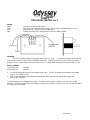
Wiring:
GND - Connect to a main ground location.
PWR - Connect to fused switched 12VDC power. (An accessory terminal will work for this.)
DIM - Night Dimming: connect to the head light switch.
SND - Voltage measuring point, usually jumper over to the PWR terminal.
Mounting:
The Series I gauge requires a rectangular hole 2-9/16“ x 1-11/16“. . It should be inserted into the opening
from the front and the U-clamp will be installed from the back. Tighten the two nuts on the U-clamp so that the
gauge is secure. Gauge depth to the back of the case is 1”. Gauge depth including the mounting studs is 1-7/8”.
Factory settings:
Lo warning point: 11.1VDC
Hi warning point: 15.4VDC
• The voltage gauge will operate in the voltage range of 8.0 – 17.0VDC and read correct between the voltage
range of 1.0 - 18.0VDC volts.
• It has a user adjustable lower and upper warning level, which can be set to indicate low voltage and
overcharging conditions.
The SND terminal is the voltage sensing input. To read the vehicle system voltage, connect this to the PWR
terminal. To read the voltage at a second battery or other remote location, connect a wire from the SND terminal to
the voltage to be monitored.

MAN# 650045
Setting the warning limits:
The SND terminal is used to enter and change the warning settings. You will need a wire connected to the
SND terminal that can be powered separate from the gauge. The headlights should be off or the DIM terminal
unhooked so that it does not interfere with the setup.
1. To enter the set mode, turn the key on with the SND wire not powered. The gauge will display “SEt”.
2. Power the SND wire. The gauge will display “ HI”. (If you wait too long the gauge will exit the setup routine
and you will need to repeat step # 1).
3. Release the SND wire. The gauge will display a number between 13.9 and 16.9.
4. Each time you momentarily power the SND wire the number will increase by one.
5. When the desired high warning value is displayed, keep the SND wire powered for about 2 seconds. The
gauge will display “LO”.
6. Release the SND wire. The gauge will display a number between 9.7 and 12.6.
7. Each time you momentarily power the SND wire the number will increase by one.
8. When the desired low warning value is displayed, keep the SND wire powered for about 2 seconds. The
gauge will display “--”.
9. Turn the key off.
Troubleshooting guide.
Problem Possible cause Solution
Gauge will not light up PWR terminal does not have power. Connect to a location that has power.
GND terminal does not have a good Connect to a different ground location.
ground.
Gauge is damaged. Return gauge for service. (see instructions)
Gauge lights up, but does Loose connection on SND terminal. Reconnect wire.
not read correctly. Poor ground connection. Move ground to different location
Gauge sender setup is incorrect. See “Setting sender setup” in the manual.
Voltage or wiring problem in the Check wiring harness for loose or damaged wires.
vehicle wiring harness.
Gauge lights up, but displays Gauge is damaged. Gauge must be returned for service. (see instructions)
“Er0”.
Gauge lights up, but displays SND terminal is shorted to ground. Check wire for damaged insulation. Replace if necessary.
“---”. Sender is damaged. Replace sender.
Gauge lights up, but displays Sender is not connected to gauge. Connect SND terminal on gauge to sender terminal.
“EEE”. Wire between gauge and sender is Test and replace wire.
broken.
Sender is not grounding properly. Sender grounds through it’s mounting plate. Make sure the mounting
plate has a good ground
Sender is damaged. Replace sender.
Gauge is damaged. Return gauge for service. (see instructions)
Gauge lights up, but displays Gauge is not calibrated correctly. Gauge must be recalibrated. (contact factory)
“Er3”.
Gauge lights up, but displays Warning limits are not set properly. See “Setting the warning limits” in the manual.
“Er5”.
Gauge flashes constantly. Warning limits are not set properly. Reset warning limits.
Vehicle is over or under charging. Check alternator and battery.
SND terminal is not connected. Make sure SND terminal is connected properly.
Gauge will not dim. DIM terminal is not connected correctly. Check wiring connections.
Gauge remains dim at all DIM terminal is getting power all Connect DIM wire to location that only has power when the headlights
times. of the time. are on.
Battery is very low. Recharge or replace vehicle battery.
Gauge is damaged. Return gauge for service. (see instructions)

MAN# 650045
Technical specifications
Minimum operating voltage - 7VDC
Maximum operating voltage - 17VDC
(operating at or near maximum voltage for an extended time can damage unit)
Gauge Resolution - 0.1VDC
Low Warning Range - 9.6 – 12.6VDC
High Warning Range - 13.9 – 16.9VDC
Gauge accuracy - ±0.1VDC
Typical current draw (@ 13.8V) - 0.1 A
SERVICE AND REPAIR
DAKOTA DIGITAL offers complete service and repair of its product line. In addition, technical consultation is available to help you work through any
questions or problems you may be having installing one of our products. Please read through the Troubleshooting Guide. There, you will find the solution to most
problems.
Should you ever need to send the unit back for repairs, please call our technical support line, (605) 332-6513, to request a Return Merchandise Authorization
number. Package the product in a good quality box along with plenty of packing material. Ship the product by UPS or insured Parcel Post. Be sure to include the
RMA number on the package, and include a complete description of the problem with RMA number, your full name and address (street address preferred), and a
telephone number where you can be reached during the day. Any returns for warranty work must include a copy of the dated sales receipt from your place of purchase.
Send no money. We will bill you after repair.
Dakota Digital 24 Month Warranty
DAKOTA DIGITAL warrants to the ORIGINAL PURCHASER of this product that should it, under normal use and condition, be proven defective in material
or workmanship within 24 MONTHS FROM THE DATE OF PURCHASE, such defect(s) will be repaired or replaced at Dakota Digital’s option.
This warranty does not cover nor extend to damage to the vehicle’s systems, and does not cover removal or reinstallation of the product. This Warranty
does not apply to any product or part thereof which in the opinion of the Company has been damaged through alteration, improper installation, mishandling, misuse,
neglect, or accident.
This Warranty is in lieu of all other expressed warranties or liabilities. Any implied warranties, including any implied warranty of merchantability, shall be
limited to the duration of this written warranty. Any action for breach of any warranty hereunder, including any implied warranty of merchantability, must be brought
within a period of 24 months from date of original purchase. No person or representative is authorized to assume, for Dakota Digital, any liability other than expressed
herein in connection with the sale of this product.
4510 W. 61ST St, N. Sioux Falls, SD. 57107
Phone: (605) 332-6513 FAX: (605) 339-4106
www.dakotadigital.com
©Copyright 2004 Dakota Digital Inc.
-
 1
1
-
 2
2
-
 3
3


Ask a question and I''ll find the answer in the document
Finding information in a document is now easier with AI
Related papers
-
Dakota Digital UTV-6100 Technical Manual
-
-
-
-
-
-
-
-
-