TO ENSURE SAFETY
4
TO ENSURE SAFETY
WARNING
Be sure to follow the instructions provided in the
manuals when installing the product.
It is recommended to use genuine Shimano parts only.
If parts such as bolts and nuts become loose or dam-
aged, the bicycle may suddenly fall over, which may
cause serious injury.
In addition, if adjustments are not carried out correctly,
problems may occur, and the bicycle may suddenly fall
over, which may cause serious injury.
Be sure to wear safety glasses or goggles to
protect your eyes while performing maintenance tasks
such as replacing parts.
After reading the dealer's manual thoroughly, keep it
in a safe place for later reference.
Be sure to also inform users of the following:
Be careful not to let the hemming of your clothes get
caught in the chain while riding. Otherwise you may
fall off the bicycle.
NOTE
Be sure to also inform users of the following:
If gear shifting operations do not feel smooth, wash
the derailleur and lubricate all moving parts.
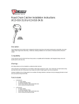
MTB/Trekking
When the chain is in any of the positions shown in the
illustration, the chain may come into contact with the
front chainring or front derailleur and generate noise.
If noise is a problem, shift the chain onto the next
largest rear sprocket or the one after if the chain is in
the position shown in Figure 1. Shift the chain onto
the next smallest sprocket or the one after if it is in the
position shown in Figure 2.
Figure 1
Figure 2
Double Triple
Front chain-
ring
Rear
sprocket
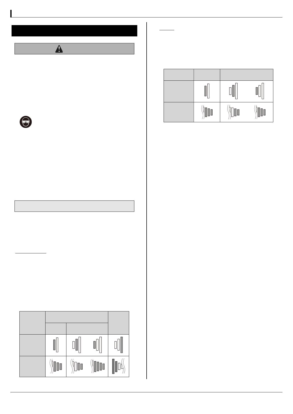
ROAD
When the chain is in any of the positions shown in the
illustration, the chain may come into contact with the
front chainring or front derailleur and generate noise.
If the noise is a problem, shift the chain onto the next
largest sprocket or the one after.
Double Triple
Front chain-
ring
Rear sprocket
For Installation to the Bicycle, and Maintenance:
A triple front derailleur cannot be used with a double
crankset because the shifting points do not match.
Similarly, a double front derailleur cannot also be used
with a triple crankset.
FD-M675, M676, 3500, A070, M785, M786
FD-M670, M671, T670, T671, 3503, T780, T781
For detailed specifications, refer to specifications on
our website for dealer's manuals.
For frames with suspension, the chainstay angle will
vary depending on whether the bicycle is being ridden
or not being ridden. When the bicycle is not being
ridden and the chain is positioned on the largest
chainring and on the smallest sprocket, the chain
guide outer plate of the front derailleur may touch
the chain.
Use an OT-SP cable and cable guide for smooth opera-
tion.
If the amount of looseness in the links is so great that
adjustment is not possible, you should replace the de-
railleur.
A special grease is used for the gear shifting cable. Do
not use premium grease or other types of grease, oth-
erwise they may cause deterioration in gear shifting
performance.
Grease the inner cable and the inside of the outer
casing before use to ensure that they slide properly.
Operation of the levers related to gear shifting should
be made only when the front chainwheel is turning.
Products are not guaranteed against natural wear and
deterioration from normal use and aging.
For maximum performance we highly recommend
Shimano lubricants and maintenance products.