
One Holland, Irvine, California 92618, U.S.A. Phone: +1-949-951-5003
High Tech Campus 92, 5656 AG Eindhoven, The Netherlands Phone: +31-402-612222
3-77 Oimatsu-cho, Sakai-ku, Sakai-shi, Osaka 590-8577, Japan
Please note: specifi cations are subject to change for improvement without notice. (English)
© Dec. 2017 by Shimano Inc. ITP
UM-3TK0A-004-00
User's manual
Rear Freehub
(for Disc Brake)
User's manuals in other languages are available at :
http://si.shimano.com
IMPORTANT NOTICE
•
Contact the place of purchase or a bicycle dealer for information on installation
and adjustment of the products which are not found in the user's manual. A
dealer's manual for professional and experienced bicycle mechanics is available
on our website (http://si.shimano.com).
•
Do not disassemble or alter this product.
For safety, be sure to read this user's manual thoroughly
before use, and follow them for correct use.
Important Safety Information
Guidelines that require replacement, contact the place of purchase or a bicycle
dealer.
WARNING
•
Check that the wheels are fastened securely before riding the bicycle. If the
wheels are loose in any way, they may come off the bicycle and serious injury
may result.
•
If the quick release lever is on the same side as the
disc brake rotor, there is the danger that it may
interfere with the disc brake rotor. Make sure that
even if the quick release lever is tightened with your
palm with all your strength, the quick release lever
does not interfere with the disc brake rotor. If the
lever interferes with the disc brake rotor, stop using
the wheel and consult a dealer or an agency.
Quick release
lever
Disc brake
rotor
•
After reading the user's manual carefully, keep it in a safe place for later
reference.
Note
•
Do not apply any lubricant to the inside of the hub, otherwise the grease will
come out.
•
If the quick release lever can be easily pushed to the CLOSE position, this means
the clamping strength is insuffi cient. Return the quick release lever to the
position perpendicular to the bicycle frame and again turn the adjusting nut
clockwise to increase the clamping strength. Push the quick release lever back to
the CLOSE position.
Adjusting nut
•
If the clamping strength is adjusted too strong and the quick release lever
cannot be pushed to the CLOSE position, turn the adjusting nut in a counter-
clockwise direction to reduce the clamping strength. When doing this, do not
fully release the adjuster nut. Turn it 1/8 of a revolution, and then try to push
the lever to CLOSE, to set the maximum clamping strength with which
you can push the quick release lever to the CLOSE position.
Turn 1/8 revolution
at a time
•
Products are not guaranteed against natural wear and deterioration from
normal use and aging.
•
For maximum performance we highly recommend Shimano lubricants and
maintenance products.
Regular inspections before riding the bicycle
Before riding the bicycle, check the following items. If any problems are found
with the following items, contact the place of purchase or a bicycle dealer.
•
Are the wheels fi xed?
•
Do the wheels rotate smoothly?
•
Are there any abnormal noises?
Names of parts
Quick release lever
Rear freehub
What is a Quick Release?
It is a mechanism that uses a single quick release lever operation on the hub to
enable the wheel to be easily installed and removed.
Quick Release function
When the quick release lever is brought to the closed position, the lever nut moves
inward. The force of this clamps the wheel to the frame and holds the wheel
securely in place.
CLOSE position
Open position
Adjusting nut
Lever nut
Quick release lever
The clamping strength is adjusted by turning the adjusting nut. When the nut is
turned in a clockwise direction, the clamping strength increases, and when the nut
is turned in a counter-clockwise direction, the clamping strength decreases.
Adjusting nut
Weaker
Stronger
Suitable dimensions of the rear end
Be sure to use only rear end widths with suitable dimensions.
Cannot use fork thicknesses less than 6 mm.
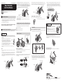
Operation
How to fasten this quick release hub
1. Move the quick release lever to the OPEN position and set the wheel so it fi rmly
touches the interior of the rear end (See sketch below).
OPEN position
OPEN position
OK Not OK
2. Open and close the quick release lever with your right hand while gradually
tightening the adjusting nut with your left hand in the clockwise direction.
Continue tightening the nut until you feel resistance with your hand at the
point when the lever is parallel to the hub (as indicated by the dotted position
in the diagram on the right).
Adjusting nut
Quick release lever
3. Grip the rear end with your fi ngers and use the palm of your hand to close the
quick release lever with as much strength as possible. When closed, the quick
release lever must be in the "CLOSE" position shown below in the diagram on
the right. The side of the lever with the inscription "CLOSE" must be facing
away from the bicycle, and the lever should be parallel to the rear end as shown
below in the diagram on the left.
Tightening torque:
5.0 -7.5 N·m {44 -66 in. lbs.}
Rear end
Quick
release
lever
CLOSE position
CAUTION
•
Never fasten a wheel to a frame by rotating the
quick release lever as shown in the diagram on
the right.
Simply rotating the lever in a circular motion will
not fasten the wheel to the frame.
Detachment of the wheel as a result of improper
hub installation can result in serious bodily injury.
Positioning of the quick release lever
For safety, the quick release lever should be along the bicycle frame when in the
CLOSE position.
Removing the wheel
Move the quick release lever from the CLOSE position to the OPEN position.
And then remove the wheel.
OPEN position
-
 1
1

Ask a question and I''ll find the answer in the document
Finding information in a document is now easier with AI
Related papers
-
Shimano FH-2400 User manual
-
Shimano FH-S028 User manual
-
Shimano SM-CB90 User manual
-
Shimano HB-T3000 User manual
-
Shimano FH-RS770 User manual
-
Shimano HB-RS505 Dealer's Manual
-
Shimano HB-M7010 Dealer's Manual
-
Shimano WH-U5000-R12 User manual
-
Shimano HB-M3050 Dealer's Manual
-
Shimano WH-M9000-TU-29 User manual
Other documents
-
Trek LeMond Owner's manual
-
Cannondale Synapse Owner's manual
-
-
BMW Mountain Bike Enduro Owner's manual
-
 BULLS Bosch Purion - 2020 & 2021 Models Owner's manual
-
-
 WTB IU2-0508-1 User manual
-
Green Light Urban Ryder Electric Bicycle User manual
-
 BULLS Brose 14D - E-Stream EVO AM 45 Owner's manual
-
 BULLS Brose Marquardt - E-Streams Owner's manual


