Grizzly Sander G0529 User manual
- Category
- Power tools
- Type
- User manual
This manual is also suitable for

COPYRIGHT © SEPTEMBER, 2003 BY GRIZZLY INDUSTRIAL, INC.
WARNING: NO PORTION OF THIS MANUAL MAY BE REPRODUCED IN ANY SHAPE
OR FORM WITHOUT THE WRITTEN APPROVAL OF GRIZZLY INDUSTRIAL, INC.
PRINTED IN TAIWAN
ONLINE MANUAL DISCLAIMER
THE INFORMATION IN THIS MANUAL REPRESENTS THE CONFIGURATION OF THE MACHINE AS IT IS CURRENTLY BEING SHIPPED. THE MACHINE
CONFIGURATION CAN CHANGE AS PRODUCT IMPROVEMENTS ARE INCORPORATED. IF YOU OWN AN EARLIER VERSION OF THE MACHINE, THIS
MANUAL MAY NOT EXACTLY DEPICT YOUR MACHINE . CONTACT CUSTOMER SERVICE IF YOU HAVE ANY QUESTIONS ABOUT DIFFERENCES. PRE-
VIOUS VERSIONS ARE NOT AVAILABLE ONLINE.
OSCILLATING SPINDLE &
12" DISC SANDER
MODEL G0529
INSTRUCTION MANUAL

WARNING
Some dust created by power sanding, sawing,
grinding, drilling, and other construction activi-
ties contains chemicals known to the State of
California to cause cancer, birth defects or
other reproductive harm. Some examples of
these chemicals are:
• Lead from lead-based paints.
• Crystalline silica from bricks, cement,
and other masonry products.
• Arsenic and chromium from chemically
treated lumber.
Your risk from these exposures varies, depend-
ing on how often you do this type of work. To
reduce your exposure to these chemicals: work
in a well ventilated area, and work with
approved safety equipment, such as those dust
masks that are specially designed to filter out
microscopic particles.

SECTION 1: SAFETY............................................................................................................................2
Safety Instructions For Power Tools ..............................................................................................2
SECTION 2: INTRODUCTION ..............................................................................................................5
SECTION 3: CIRCUIT REQUIREMENTS ............................................................................................6
110 Volt ..........................................................................................................................................6
Extension Cords..............................................................................................................................7
Grounding........................................................................................................................................7
SECTION 4: MACHINE FEATURES ....................................................................................................8
SECTION 5: SET UP ............................................................................................................................9
Unpacking ......................................................................................................................................9
Parts Inventory ................................................................................................................................9
Hardware Recognition Chart ........................................................................................................10
Clean Up ......................................................................................................................................11
Site Considerations ......................................................................................................................11
Cabinet Assembly ........................................................................................................................12
Beginning Assembly......................................................................................................................12
Mounting Sander ..........................................................................................................................13
Installing Spindle ..........................................................................................................................13
Table Inserts ................................................................................................................................14
Squaring Table..............................................................................................................................14
Squaring Disc Sander ..................................................................................................................15
Sanding Disc ................................................................................................................................16
Aligning Table ..............................................................................................................................16
Miter Gauge ..................................................................................................................................17
Dust Collection ..............................................................................................................................17
SECTION 6: OPERATIONS ................................................................................................................18
General..........................................................................................................................................18
Power Switch ................................................................................................................................18
Spindle Sanding ............................................................................................................................19
SECTION 7: MAINTENANCE ............................................................................................................21
Maintenance Log ..........................................................................................................................22
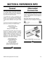
SECTION 8: REFERENCE INFO ........................................................................................................23
General..........................................................................................................................................23
Aftermarket ..................................................................................................................................23
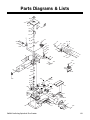
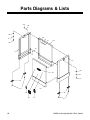
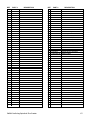
Parts Diagrams & Lists ................................................................................................................25
Troubleshooting ............................................................................................................................29
Warranty & Returns ......................................................................................................................30
Table of Contents

-2-
G0529 Oscillating Spindle & Disc Sander
5. KEEP CHILDREN AND VISITORS
AWAY. All children and visitors should be
kept at a safe distance from work area.
6. MAKE WORKSHOP CHILD PROOF with
padlocks, master switches, or by removing
starter keys.
7. NEVER FORCE TOOL. It will do the job
better and safer at the rate for which it was
designed.
8. USE RIGHT TOOL. DO NOT force tool or
attachment to do a job for which it was not
designed.
1. KEEP GUARDS IN PLACE and in working
order.
2. REMOVE ADJUSTING KEYS AND
WRENCHES. Form a habit of checking to
see that keys and adjusting wrenches are
removed from tool before turning on.
3. KEEP WORK AREA CLEAN. Cluttered
areas and benches invite accidents.
4. NEVER USE IN DANGEROUS ENVIRON-
MENT. DO NOT use power tools in damp
or wet locations, or where any flammable
or noxious fumes may exist. Keep work
area well lighted.
For Your Own Safety Read Instruction
Manual Before Operating This Equipment
Indicates an imminently hazardous situation which, if not avoided,
WILL result in death or serious injury.
Indicates a potentially hazardous situation which, if not avoided,
COULD
result in death or serious injury.
Indicates a potentially hazardous situation which, if not avoided,
MAY
result in minor or moderate injury. It may also be used to alert
against unsafe practices.
This symbol is used to alert the user to useful information about
proper operation of the equipment.
The purpose of safety symbols is to attract your attention to possible hazardous conditions.
This manual uses a series of symbols and signal words which are intended to convey the level
of importance of the safety messages. The progression of symbols is described below.
Remember that safety messages by themselves do not eliminate danger and are not a substi-
tute for proper accident prevention measures.
NOTICE
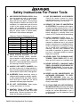
Safety Instructions For Power Tools
SECTION 1: SAFETY

G0529 Oscillating Spindle & Disc Sander -3-
9. USE PROPER EXTENSION CORD. Make
sure your extension cord is in good condi-
tion. Conductor size should be in accor-
dance with the chart below. The amperage
rating should be listed on the motor or tool
nameplate. An undersized cord will cause
a drop in line voltage resulting in loss of
power and overheating. Your extension
cord must also contain a ground wire and
plug pin. Always repair or replace exten-
sion cords if they become damaged.
Minimum Gauge for Extension Cords
10. WEAR PROPER APPAREL. DO NOT
wear loose clothing, gloves, neckties,
rings, bracelets, or other jewelry which may
get caught in moving parts. Non-slip
footwear is recommended. Wear protective
hair covering to contain long hair.
11. ALWAYS USE SAFETY GLASSES. Also
use face or dust mask if cutting operation is
dusty. Everyday eyeglasses only have impact
resistant lenses, they are NOT safety glasses.
12. ALLERGIES: Certain wood may cause an
allergic reaction in people or animals, especial-
ly when exposed to fine dust. Make sure you
know what type of wood dust you will be
exposed to and wear proper respirators.
13. DO NOT OVER-REACH. Keep proper
footing and balance at all times.
14. MAINTAIN TOOLS WITH CARE. Keep
tools sharp and clean for best and safest
performance. Follow instructions for lubri-
cating and changing accessories.
LENGTH
AMP RATING 25ft 50ft 100ft
0-6 16 16 16
7-10 16 16 14
11-12 16 16 14
13-16 14 12 12
17-20 12 12 10
21-30 10 10 No
Safety Instructions For Power Tools
15. USE RECOMMENDED ACCESSORIES.
Consult the owner’s manual for recom-
mended accessories. The use of improper
accessories may cause risk of injury.
16. REDUCE THE RISK OF UNINTENTION-
AL STARTING. On machines with magnet-
ic contact starting switches there is a risk of
starting if the machine is bumped or jarred.
Always disconnect from power source
before adjusting or servicing. Make sure
switch is in OFF position before reconnecting.
17. CHECK DAMAGED PARTS. Before fur-
ther use of the tool, a guard or other part
that is damaged should be carefully
checked to determine that it will operate
properly and perform its intended function.
Check for alignment of moving parts, bind-
ing of moving parts, breakage of parts,
mounting, and any other conditions that
may affect its operation. A guard or other
part that is damaged should be properly
repaired or replaced.
18. NEVER LEAVE TOOL RUNNING UNAT-
TENDED. TURN POWER OFF. DO NOT
leave tool until it comes to a complete stop.
19. NEVER OPERATE A MACHINE WHEN
TIRED, OR UNDER THE INFLUENCE OF
DRUGS OR ALCOHOL. Full mental alert-
ness is required at all times when running a
machine.
20. NEVER ALLOW UNSUPERVISED OR
UNTRAINED PERSONNEL TO OPER-
ATE THE MACHINE. Make sure any
instructions you give in regards to machine
operation are approved, correct, safe, and
clearly understood.
21. IF AT ANY TIME YOU ARE EXPERIENC-
ING DIFFICULTIES performing the intend-
ed operation, stop using the machine! Then
contact our service department or ask a
qualified expert how the operation should
be performed.

-4-
G0529 Oscillating Spindle & Disc Sander
No list of safety guidelines can be com-
plete. Every shop environment is different.
Always consider safety first, as it applies to
your individual working conditions. Use
this and other machinery with caution and
respect. Failure to follow guidelines could
result in serious personal injury, damage to
equipment or poor work results.
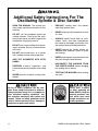
Additional Safety Instructions For The
Oscillating Spindle & Disc Sander
• READ THIS MANUAL. This manual con-
tains proper operating instructions for this
machine.
• DO NOT jam the workpiece against the
sanding surfaces. Firmly grasp the work-
piece in both hands and ease it against the
spindle/disc using light pressure.
• DO NOT wear loose clothing while operat-
ing this machine. Roll up or button sleeves
at the cuff.
• DO NOT place hands near, or in contact
with, sanding surfaces during operation.
• GRIP THE WORKPIECE WITH BOTH
HANDS.
• PERFORM machine inspections and
maintenance service promptly when called
for.
• NEVER leave the machine running unat-
tended.
• REPLACE sanding discs and sleeves
when they become worn.
• NEVER sand more than one piece of stock
at a time.
• ALWAYS inspect board stock for nails,
staples, knots, and other imperfections
that could be dislodged and thrown from
the machine during sanding operations.
• NEVER operate the sander without an
adequate dust collection system in place
and running.
• NEVER sand tapered or pointed stock with
the point facing the feed direction.
• DISCONNECT THE MACHINE FROM
THE POWER SOURCE before changing
the sanding disc or sleeve.
• TEST RUN THE MACHINE before starting
any work.
Always wear a respira-
tor when operating the
Model G0529. Using this
machine produces saw-
dust which may cause
allergic reactions or res-
piratory problems.

G0529 Oscillating Spindle & Disc Sander -5-
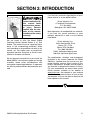
We are proud to offer the Model G0529
Oscillating Vertical Spindle Sander & 12" Disc
Sander. This machine is part of a growing Grizzly
family of fine woodworking machinery. When
used according to the guidelines set forth in this
manual, you can expect years of trouble-free,
enjoyable operation and proof of Grizzly’s com-
mitment to customer satisfaction.
We are pleased to provide this manual with the
Model G0529. It was written to guide you through
assembly, review safety considerations, and
cover general operating procedures. It represents
our effort to produce the best documentation pos-
sible.
If you have any comments regarding this manual,
please write to us at the address below:
Grizzly Industrial, Inc.
C
/O Technical Documentation
P.O. Box 2069
Bellingham, WA 98227-2069
Most importantly, we stand behind our machines.
If you have any service questions or parts
requests, please call or write us at the location
listed below.
Grizzly Industrial, Inc.
1203 Lycoming Mall Circle
Muncy, PA 17756
Phone: (570) 546-9663
Fax: (800) 438-5901
E-Mail: [email protected]
Web Site: http://www.grizzly.com
The specifications, drawings, and photographs
illustrated in this manual represent the Model
G0529 as supplied when the manual was pre-
pared. However, owing to Grizzly’s policy of con-
tinuous improvement, changes may be made at
any time with no obligation on the part of Grizzly.
For your convenience, we always keep current
Grizzly manuals available on our website at
www.grizzly.com
. Any updates to your machine
will be reflected in these manuals as soon as they
are complete. Visit our site often to check for the
latest updates to this manual!
SECTION 2: INTRODUCTION
Lack of familiarity with
this manual could
cause serious person-
al injury. Become
familiar with the con-
tents of this manual,
including all the safety
warnings.

-6-
G0529 Oscillating Spindle & Disc Sander
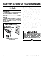
Amperage Draw
The Model G0529 1 HP motor is wired to operate
at 110V and will draw the following load:
Motor Load............................................10 Amps
Plug Type
The Model G0529 is supplied with a NEMA 5-15
plug. DO NOT modify the plug or power cord in
any way. See Figure 1 for a NEMA 5-15 plug and
grounded outlet.
Circuit Breaker Requirements
We recommend that the circuit you use your
machine on should be dedicated. Use the follow-
ing guidelines when choosing a circuit breaker for
your machine (circuit breakers rated any higher
are not adequate to protect the circuit):
Recommended Circuit Breaker ..............15 Amp
Your Circuit Capacity
Always check to see if the wires in your circuit are
capable of handling the amperage load from your
machine. If you are unsure, consult a qualified
electrician.
If you operate this machine on any circuit that is
already close to its capacity, it might blow a fuse
or trip a circuit breaker. However, if an unusual
load does not exist and a power failure still
occurs, contact a qualified electrician or our
Service Department at (570) 546-9663.
Serious personal injury could occur if you
connect your machine to the power source
before you have completed the assembly
process. DO NOT connect the machine to
the power source until instructed to do so.
Figure 1. NEMA 5-15 plug and
grounded outlet.
110 Volt
SECTION 3: CIRCUIT REQUIREMENTS

G0529 Oscillating Spindle & Disc Sander -7-
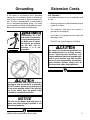
Grounding
In the event of an electrical short, grounding
reduces the risk of electric shock by providing a
path of least resistance to disperse electric cur-
rent. This tool is equipped with a power cord that
has an equipment-grounding prong. The outlet
must be properly installed and grounded in accor-
dance with all local codes and ordinances.
110V Operation
If you find it necessary to use an extension cord
at 110V:
• Make sure the cord is rated Standard Service
(grade S) or better.
• The extension cord must also contain a
ground wire and plug pin.
• Use at least a 16 gauge cord if the cord is 50
feet long or less.
•DONOT use a cord longer that 100 feet!
Extension Cords
This machine must have a ground prong in
the plug to help ensure that it is grounded.
DO NOT remove ground prong from plug to
fit into a two-pronged outlet! If the plug will
not fit the outlet, have the proper outlet
installed by a qualified electrician.
Electrocution or a fire
can result if the machine
is not grounded correct-
ly. Make sure all electri-
cal circuits are ground-
ed. DO NOT use the
machine if it is not
grounded.
No single list of electrical guidelines can
be comprehensive for all shop environ-
ments. Operating this machinery may
require additional electrical upgrades spe-
cific to your machine and shop environ-
ment. It is your responsibility to make sure
your electrical systems comply with all
local electrical codes and ordinances.
NOTICE
The wire on the power cord with green or
green and yellow striped insulation is the
grounding conductor.

-8-
G0529 Oscillating Spindle & Disc Sander
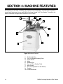
1. Sanding Spindle
2. Cast Iron Spindle Sanding Table
3. Power Switch
4. Motor
5. Sanding Disc
6. Cast Iron Disc Sanding Table
7. Miter Gauge
8. Dust Ports (Spindle Port Not Shown)
9. Cabinet
10. Graduated Scales
SECTION 4: MACHINE FEATURES
Figure 2. Machine Features.
An important part of safety is knowing your machine and its components. Take the time to familiarize
yourself with the features of your new G0529 Oscillating Spindle & 12" Disc Sander. They will be fre-
quently mentioned throughout the instructions in this manual.
1
10
9
8
7
6
5
4
3
2

G0529 Oscillating Spindle & Disc Sander -9-
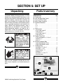
The Model G0529 Oscillating Spindle & 12" Disc
Sander was carefully packed at the factory. If you
discover the machine is damaged after you have
signed for delivery, and the truck and driver are
gone, you will need to file a freight claim with the
carrier. Save the containers and all packing mate-
rials for possible inspection by the carrier or its
agent. Without the packing materials, filing a
freight claim can be difficult. If you need assis-
tance determining whether you need to file a
freight claim, or with the procedure to file one,
please contact our Customer Service.
When you are completely satisfied with the con-
dition of your shipment, you should inventory its
parts.
DESCRIPTION Qty
A. Sander unit . . . . . . . . . . . . . . . . . . . . . . .1
B. Left and Right Side Panels . . . . . . . . . . .2
C. Front and Pear Panels . . . . . . . . . . . . . .2
D. Miter Gauge Assembly . . . . . . . . . . . . . .1
E. Spindle Assemblies
• 2" . . . . . . . . . . . . . . . . . . . . . . . . . . . .1
• 1
1
⁄2
" . . . . . . . . . . . . . . . . . . . . . . . . . . .1
•
5
⁄8
" . . . . . . . . . . . . . . . . . . . . . . . . . . . .1
•
1
⁄4 " . . . . . . . . . . . . . . . . . . . . . . . . . . . .1
F. Table Inserts
• Oval Table Insert 2" . . . . . . . . . . . . . . .1
• Table Insert 2" . . . . . . . . . . . . . . . . . . .1
• Oval Table Insert
3
⁄4" . . . . . . . . . . . . . . .1
• Table Insert
3
⁄4" . . . . . . . . . . . . . . . . . . .1
G. Rubber Floor Pads
• Flat Head Screws
5
⁄16"-18 x
3
⁄4" . . . . . . .4
• Washers
5
⁄16" . . . . . . . . . . . . . . . . . . . . .4
• Nuts
5
⁄16" . . . . . . . . . . . . . . . . . . . . . . .4
H. Wrench Hardware Bag
• Open End Wrench 17mm . . . . . . . . . . .2
• Open End Wrench 12mm . . . . . . . . . . .1
I. Hardware Bag
• Hex Bolts
5
⁄16"-18 x
3
⁄4" . . . . . . . . . . . . . .8
• Hex Nuts
5
⁄16"-18 . . . . . . . . . . . . . . . . .10
• Lock Washers
5
⁄
16" . . . . . . . . . . . . . . .10
• Washers
5
⁄16" . . . . . . . . . . . . . . . . . . . .18
• Hex Bolts
5
⁄16"-18 x 1
1
⁄4" . . . . . . . . . . . . .2
• Hex Key 6mm . . . . . . . . . . . . . . . . . . . .1
Figure 2. G0529 inventory.
The Model G0529
weighs 143 lbs.
Personal injury could
occur if the machine is
moved without addition-
al assistance. Seek help
when moving or lifting
the machine.
Sharp edges on metal
parts may cause person-
al injury. Examine the
edges of all metal parts
before handling.
B
E
C
A
F
D
H
G
I
Parts InventoryUnpacking
SECTION 5: SET UP

-10-
G0529 Oscillating Spindle & Disc Sander
5mm
10mm
15mm
20mm
25mm
30mm
35mm
40mm
45mm
50mm
55mm
60mm
65mm
70mm
75mm
Washer
Lock
Washer
Hex
Nut
Wing
Nut
Phillips
Head
Sheet
Metal
Screw
Setscrew
Phillips
Head
Screw
Thumb
Screw
Slotted
Screw
Countersunk
Phillips
Head
Screw
Cap
Screw
Carriage
Bolt
Hex
Head
Bolt
Button
Head
Screw
Flange
Bolt
Phillips
Head
Hex
Bolt
Lock
Nut
5
⁄16''
1
⁄4''
3
⁄8''
1
⁄2''
5
⁄8''
7
⁄16''
9
⁄16''
3
⁄4''
7
⁄8''
1''
1
1
⁄4''
1
1
⁄2''
1
3
⁄4''
2
2
1
⁄4''
2
1
⁄2''
2
3
⁄4''
3
LINES ARE 1MM APART
LINES ARE
1
⁄16'' INCH APART
5
⁄8''
W
A
S
H
E
R
D
I
A
M
E
T
E
R
9
⁄16''
W
A
S
H
E
R
D
I
A
M
E
T
E
R
1
⁄2''
W
A
S
H
E
R
D
I
A
M
E
T
E
R
12mm
W
A
S
H
E
R
D
I
A
M
E
T
E
R
10mm
W
A
S
H
E
R
D
I
A
M
E
T
E
R
7
⁄16''
W
A
S
H
E
R
D
I
A
M
E
T
E
R
8mm
W
A
S
H
E
R
D
I
A
M
E
T
E
R
3
⁄8''
W
A
S
H
E
R
D
I
A
M
E
T
E
R
5
⁄16''
W
A
S
H
E
R
D
I
A
M
E
T
E
R
1
⁄4''
W
A
S
H
E
R
D
I
A
M
E
T
E
R
#
10
W
A
S
H
E
R
D
I
A
M
E
T
E
R
4mm
W
A
S
H
E
R
D
I
A
M
E
T
E
R
6mm
W
A
S
H
E
R
D
I
A
M
E
T
E
R
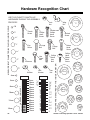
WASHERS ARE MEASURED BY THE INSIDE DIAMETER
MEASURE BOLT DIAMETER BY PLACING INSIDE CIRCLE
#
10
1
⁄4''
5
⁄16''
3
⁄8''
7
⁄16''
1
⁄2''
5
⁄8''
4mm
6mm
8mm
10mm
12mm
16mm
USE THIS CHART TO MATCH UP
HARDWARE DURING THE ASSEMBLY
PROCESS!
Hardware Recognition Chart

G0529 Oscillating Spindle & Disc Sander -11-
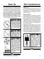
Site Considerations
Clean Up
The unpainted surfaces are coated with a waxy
oil to protect them from corrosion during ship-
ment. Remove this protective coating with a sol-
vent cleaner or citrus-based degreaser such as
Grizzly’s G7895 Degreaser. To clean thoroughly,
some parts may need to be removed. For opti-
mum performance from your machine, make
sure you clean all moving parts or sliding
contact surfaces that are coated. Avoid chlo-
rine-based solvents as they may damage painted
surfaces should they come in contact.
Gasoline and petroleum
products have low flash
points and could explode
if used to clean machin-
ery. DO NOT use gaso-
line or petroleum prod-
ucts to clean the machin-
ery.
Smoking near solvents
could ignite an explosion
or fire and cause serious
injury. DO NOT smoke
while using solvents.
Lack of ventilation while
using solvents could
cause serious personal
health risks, fire, or
environmental hazards.
Always work in a well
ventilated area to pre-
vent the accumulation
of dangerous fumes.
Supply the work area
with a constant source
of fresh air.
Unsupervised children
and visitors inside your
shop could receive seri-
ous personal injury.
Ensure child and visitor
safety by keeping all
entrances to the shop
locked at all times. DO
NOT allow unsupervised
children or visitors in the
shop at any time.
Weight Load
The Model G0529 weighs 143 lbs. and has a
21
1
/4" X 16
1
/2" footprint. Most shop floors should
be sufficient to carry the weight of the machine.
Reinforce the floor if you question its ability to
support the weight.
Working Clearance
Working clearances can be thought of as the dis-
tances between machines and obstacles that
allow safe operation of every machine without
limitation. Consider existing and anticipated
machine needs, size of material to be processed
through each machine, and space for auxiliary
stands or work tables. Also consider the relative
position of each machine to one another for effi-
cient material handling.
Lighting And Outlets Lighting should be bright
enough to eliminate shadow and prevent eye
strain. Electrical circuits should be dedicated or
large enough to handle the amperage draw.
Outlets should be located near each machine so
power or extension cords are clear of high-traffic
areas. Observe local electrical codes for proper
installation of new lighting, outlets, or circuits.

-12-
G0529 Oscillating Spindle & Disc Sander
Beginning Assembly
Loose hair and clothing
could get caught in
machinery and cause
serious personal injury.
Keep loose clothing
rolled up and long hair
tied up and away from
machinery.
Serious personal injury
could occur if you con-
nect your machine to the
power source before you
have completed the
assembly process. DO
NOT connect the
machine to the power
source until instructed to
do so.
!
Sharp edges on metal
parts may cause person-
al injury. Examine the
edges of all metal parts
before handling.
This section will cover the basic assembly and
adjustment instructions needed to begin opera-
tion. Complete the assembly in the order provid-
ed in this manual and then read the remaining
portion of the manual before attempting any type
of operation.
Your safety is important! Please follow the
warnings below during this entire section:
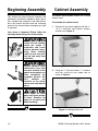
Cabinet Assembly
Figure 3. Assembled panels.
Figure 4. Installing rubber feet.
The Model G0529 Sander mounts on a sturdy
cabinet stand.
To assemble the cabinet stand:
1. Connect all four panels together with the
5
⁄16"
-18 x
3
/4" hex bolts, lock washers, washers
and hex nuts (Figure 3).
2. Using the
5
⁄16" flat head screws,
5
⁄16" washers
and nuts, install the four rubber feet as
shown in Figure 4.

G0529 Oscillating Spindle & Disc Sander -13-
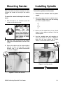
Installing SpindleMounting Sander
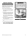
To install the spindle onto the sander:
1. Disconnect the machine from the power
supply.
2. Select the proper diameter of spindle sleeve.
The Model G5029 comes with the following
four sizes of spindle sleeves:
•
1
⁄4"
•
5
⁄8"
• 1
1
⁄2"
•2"
3. Make sure the tapered end of the spindle
sleeve is clean before installing it into the
sander spindle.
4. Use the supplied open end wrenches to
secure the spindle as shown in Figure 6.
Note—Do not over tighten the spindle
sleeve, it could make removal difficult.
Figure 6. Installing spindle.
!
Figure 5. Cabinet hole location.
When the cabinet has been completed, it is time
to place the sander unit on top of the cabinet
stand.
To mount the sander to the top of the cabinet
stand:
1. With the help of an assistant, place the
sander on the cabinet stand.
The Model G0529
weighs 143 lbs.
Personal injury could
occur if the machine is
moved without addition-
al assistance. Seek help
when moving or lifting
the machine.
2. Align the holes on the rim of the cabinet
sides with the threaded holes in the rim of the
sander.
3. Secure the cabinet and the sander together
with the
5
⁄16"-18 x 1
1
⁄4" hex bolts,
5
⁄16" lock
washers, and
5
⁄16" flat washers combination
as shown in Figure 5.
!

-14-
G0529 Oscillating Spindle & Disc Sander
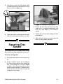
To square the sanding tables:
1. Disconnect the machine from the power sup-
ply.
2. Set the table at 90˚ as shown in Figure 8.
3. Place a machinist square on the table and
against the sanding spindle to verify the table
is 90˚ from the edge of the sanding sleeve as
shown in Figure 9.
4. Adjust the pointer to 90˚.
Figure 8. Setting the table scale at 90˚.
Figure 9. Squaring the table and spindle.
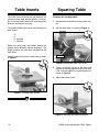
Figure 7. Installing table inserts.
Squaring TableTable Inserts
The table inserts minimize the gap between the
working surface edge and the spindle. It is impor-
tant to use the proper table insert according to the
diameter spindle you are using.
The Model G5029 comes with the following four
table inserts:
• 2"
• 1"
• 2" elliptical
• 1" elliptical
Select the table insert that comes closest the
spindle sleeve diameter without touching it. The
elliptical inserts are used when sanding with the
table tilted.
Place the table insert into the table hole as shown
in Figure 7.
!
!
!
Pointer

G0529 Oscillating Spindle & Disc Sander -15-
Figure 10. Squaring the sanding table.
5. If the table is not 90˚ from the spindle, adjust
the table stop bolt to allow the table to move
more as shown in Figure 10.
Figure 11. Squaring the sanding table.
Squaring Disc
Sander
The sanding tables for the spindle sander and the
disc sander have tilting capabilities from 0˚ to 45˚.
To tilt the sanding table:
1. Disconnect the machine from the power sup-
ply.
2. Using a machinist square, set one edge on
the table surface and the other against the
face of the sanding disc as shown in Figure
11. Note—This can be done with the sand-
paper installed, although it is somewhat eas-
ier to measure if the disc does not have the
sandpaper disc installed.
3. Loosen the lock lever and adjust the table
angle until it is perfectly perpendicular and
flush with both edges of the machinist
square.
4. Tighten the lock lever while holding the table
perpendicular.
5. Adjust the scale pointer to read 0˚ when the
table has been properly adjusted.
!
6. Tighten the table stop bolt against the under-
side of the table when the table is set at 90˚.

-16-
G0529 Oscillating Spindle & Disc Sander
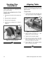
The table must be aligned to the face of the sand-
ing disc so that the sandpaper does not rub
against the table.
To align the table:
1. Loosen the bolts that secure the table to the
table support bracket as shown in Figure 13.
2. Align the table so that there is a
1
⁄16'' gap
between the 12" disc and the table.
3. Tighten the bolts loosened in step 1.
4. Spin the disc by hand to check if the sand-
paper is touching the table. Note—DO NOT
turn the disc sander on at this point.
5. Repeat steps 1-3 if the sandpaper touches
table at any point in the rotation.
Aligning Table
Figure 13. Loosening table bolts.
Figure 12. Installing sanding disc.
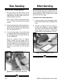
Sanding Disc
Installation
The disc sander requires 12" sanding discs with
hook and loop backing.
To install a new sanding disc on the 12" disc
sanding surface:
1. Disconnect the machine from the power sup-
ply.
2. Remove the disc sanding table.
3. Remove the old sanding disc.
4. Install the new sanding disc as shown in
Figure 12.
!
!

G0529 Oscillating Spindle & Disc Sander -17-
Figure 15. Dust ports.
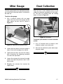
Dust CollectionMiter Gauge
There are two 2" dust collection ports for the
sander that should be connected to a dust collec-
tor. The ports are located under the sanding
tables as shown in Figure 15.
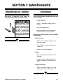
Figure 14. Squaring miter gauge to disc.
The miter gauge needs to be adjusted perpendic-
ular to the face of the wheel when it is mounted in
the table slot.
To adjust miter gauge:
1. Use a machinist square with one edge
against the face of the miter gauge and the
other against the disc face as shown in
Figure 14.
2" Dust Ports
!
2. Loosen the lock knob on the miter gauge to
adjust it flush with the edge of the square.
3. Tighten the lock knob, and verify the setting.
Note—Sometimes the tightening procedure
can affect the adjustment.
4. Loosen the setscrew that secures the angle
pointer and adjust the pointer to the 0˚ mark
on the scale.
5. Retighten the setscrew that secures the
angle pointer.
To connect your machine to a dust collection
system:
1. Use a 2" diameter hose to connect a dust
collection system to your dust ports.
2. Start the dust collection system before oper-
ating the sander.

G0529 Oscillating Spindle & Disc Sander-18-
Damage to your eyes, lungs, and ears
could result from failure to wear safety
glasses, a respirator, and hearing protec-
tion while sanding with this machine.
Loose hair and clothing
could get caught in
machinery and cause
serious personal injury.
Keep loose clothing
rolled up and long hair
tied up and away from
machinery.
This section covers basic disc sanding opera-
tions. Please read the remaining portion of the
manual before attempting any type of operation.
Your safety is important! Please follow the
warnings below during this entire section:
Operating this equipment has the potential
to propel debris into the air which can
cause eye injury. Always wear safety glass-
es or goggles when operating equipment.
Everyday glasses or reading glasses only
have impact resistant lenses, they are not
safety glasses. Be certain the safety glass-
es you wear meet the appropriate stan-
dards of the American National Standards
Institute (ANSI).
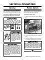
The Model G0529 sander is equipped with a pad-
dle-type power switch with a safety key.
To operate the power switch:
1. Insert the safety locking key shown in Figure
16.
Figure 16. On/Off Switch.
2. Lift the switch to start and press to stop the
motor.
3. Remove the locking key when the machine is
not in use and store the key in a safe place.
Make sure the power switch is in the OFF
position before connecting the sander to the
power source. Serious personal injury could
occur if you connect your machine to the
power source with the power switch ON.
Power Switch
General
SECTION 6: OPERATIONS
Page is loading ...
Page is loading ...
Page is loading ...
Page is loading ...
Page is loading ...
Page is loading ...
Page is loading ...
Page is loading ...
Page is loading ...
Page is loading ...
Page is loading ...
Page is loading ...
Page is loading ...
Page is loading ...
Page is loading ...
Page is loading ...
-
 1
1
-
 2
2
-
 3
3
-
 4
4
-
 5
5
-
 6
6
-
 7
7
-
 8
8
-
 9
9
-
 10
10
-
 11
11
-
 12
12
-
 13
13
-
 14
14
-
 15
15
-
 16
16
-
 17
17
-
 18
18
-
 19
19
-
 20
20
-
 21
21
-
 22
22
-
 23
23
-
 24
24
-
 25
25
-
 26
26
-
 27
27
-
 28
28
-
 29
29
-
 30
30
-
 31
31
-
 32
32
-
 33
33
-
 34
34
-
 35
35
-
 36
36


Grizzly Sander G0529 User manual
- Category
- Power tools
- Type
- User manual
- This manual is also suitable for
Ask a question and I''ll find the answer in the document
Finding information in a document is now easier with AI
Related papers

Other documents
-
Ryobi EPS80RG Owner's Operating Manual
-
Triton TSPST450 User guide
-
RIDGID EB44241 User manual
-
-
-
Husky H4820 Operating instructions
-
Rikon Power Tools 50-300 Operating instructions
-
-
Delta 31-484 Owner's manual
-