Page is loading ...

21-DEGREE
FRAMING NAILER
Model # 61793
Your new tool has been engineered and manufactured to WEN’s highest standards for dependability, ease
of operation, and operator safety. When properly cared for, this product will supply you years of rugged,
trouble-free performance. Pay close attention to the rules for safe operation, warnings, and cautions. If
you use your tool properly and for intended purpose, you will enjoy years of safe, reliable service.
IMPORTANT:
NEED HELP? CONTACT US!
Have product questions? Need technical support?
Please feel free to contact us at:
800-232-1195
WENPRODUCTS.COM
(M-F 8AM-5PM CST)
bit.ly/wenvideo
For replacement parts visit
WENPRODUCTS.COM
NOTICE: Please refer to wenproducts.com for the most up-to-date instruction manual.

TABLE OF CONTENTS
2
3
4
7
8
11
13
13
16
17
TECHNICAL DATA
Model Number:
Minimum Operating Pressure:
Maximum Operating Pressure:
Air Inlet:
Air Consumption:
Nail Type:
Nail Diameter:
Nail Length:
Angle:
Collation Type:
Magazine Capacity:
Product Dimensions:
Product Weight:
61793
70 PSI
120 PSI
1/4"- 18 NPT
5.8 CFM @ 90 PSI
Round Head Framing Nails
0.113" - 0.131" (2.87 - 3.33 mm)
2" - 3-9/16" (50 mm - 90 mm)
21°
Plastic
60 pcs
19-5/8" x 15" x 6"
9 lbs
Technical Data
Safety Introduction
Safety Rules
Know Your Framing Nailer
Preparation and Adjustments
Operation
Maintenance
Exploded View and Parts List
Troubleshooting
Warranty Statement
2

SAFETY INTRODUCTION
Hello! Thank you for purchasing the WEN Framing Nailer. Safe operation of this pneumatic tool requires that you
read and understand this operator’s manual and all labels affixed to the tool. Safety is a combination of common
sense, staying alert, and knowing how your tool works.
The purpose of the following safety symbol is to attract your attention to possible dangers. We don’t want any of
our beloved WEN customers accidentally injuring themselves. The safety symbols and the explanations with them
deserve your careful attention and understanding.
SAFETY ALERT SYMBOL: Indicates danger, warning, or caution. This may be used in conjunction
with other symbols. Always follow the safety precautions to reduce the risk of fire, electric shock and
personal injury. However, please note that the safety warnings do not by themselves eliminate any
danger. These instructions and warnings are not substitutes for proper accident prevention measures.
WARNING: Do not attempt to operate this tool until you have thoroughly read and understood all instructions,
safety rules, etc., contained in this manual. Failure to comply can result in accidents involving fire, electric shock,
or serious personal injury. Save this operator’s manual and review it frequently to maximize safety for both yourself
and others.
3

SAFETY RULES
Safety is a combination of common sense, staying alert and knowing how your item works.
SAVE THESE SAFETY INSTRUCTIONS.
WARNING: To avoid mistakes and serious injury, do not use your tool until the following steps have
been read and understood
1. READ and become familiar with this entire instruction manual, no matter how boring it may be. LEARN the
tool’s applications, limitations, and possible hazards.
2. ALWAYS keep your work area clean, uncluttered, and well lit. DO NOT work on floor surfaces that are
slippery with sawdust or wax.
3. DO NOT USE THE TOOL in the presence of flammable dust, gases or fumes. The tool may produce a
spark that could ignite gases causing a fire. Driving a nail into another nail may also cause a spark.
4. KEEP BYSTANDERS AT A SAFE DISTANCE from the work area, especially when the tool is operating.
NEVER allow children or pets near the tool.
5. MAKE THE WORKSHOP CHILDPROOF. Use padlocks and master switches and ALWAYS remove
starter keys. Keep bystanders, children and visitors away while operating the power tool. Distractions can cause
you to lose control. When tool is not in use, it should be locked away in a safe place.
6. DRESS FOR SAFETY. Do not wear loose clothing, gloves, neckties, or jewelry (rings, watches, etc.) when
operating the tool. Inappropriate clothing and items can get caught in moving parts and draw you in. ALWAYS
wear non-slip footwear and tie back long hair.
7. USE PERSONAL PROTECTIVE EQUIPMENT.
• Everyone in the work area MUST wear safety glasses with side shields that conform to ANSI Z87.1
requirements (approved glasses have “Z87” printed or stamped on them). It is the employer’s responsibility to
enforce the use of eye protection equipment by both the tool operator and others in the work area.
• Wear a face mask or dust mask to fight the debris produced by operation.
• Wear ear protection such as plugs or muffs to fight hearing loss.
• Wear work gloves to protect your hands.
8. KEEP ALERT. Watch what you are doing. Use common sense. Do not operate any tool when you are tired or
under the influence of drugs, alcohol or medication that may affect your ability to properly use the tool.
9. DO NOT OVERREACH. Keep proper footing and balance at all times. Wear oil-resistant rubber-soled
footwear. Keep the floor clear of oil, scrap, and other debris.
10. DO NOT FORCE THE TOOL to do a job for which it was not designed.
11. INSPECT TOOL BEFORE USE. Do not operate if any portion of the tool, trigger, or safety bracket is dam-
aged, inoperable, disconnected, or altered. Leaking air, damaged parts, or missing parts should be repaired or
replaced before use
12. WHEN CONNECTING TO THE AIR SUPPLY, the tool is at risk of possibly firing fasteners. Be aware of
this and do not aim the gun at anything you do not want to shoot a nail into.
4

SAFETY RULES
13. USE ONLY clean dry and regulated air. Condensation from an air compressor can rust and damage the
internal workings of the tool.
14. DO NOT USE BOTTLED GASES to power this tool. Bottled compressed gases including but not limited to
oxygen, carbon dioxide, nitrogen, hydrogen, propane, acetylene or air are not for use with pneumatic tools. Never
use combustible gases or any other reactive gas as a power source for this tool. DANGER OF EXPLOSION
AND/OR SERIOUS PERSONAL INJURY MAY RESULT.
15. REGULATE AIR PRESSURE. Use air pressure that is compatible with the ratings on the nameplate of the
tool (70 to 120 PSI).
16. USE PROPER EXTENSION CORDS. When using an air compressor outdoors, use only rounded jackets
extensions cords. These are intended for outside use. See manufacturer’s manual for the AWG required for the
compressor’s amperage draw.
17. ALL COMPONENTS including hoses, connectors, filters, regulators, etc. must have working pressure rating
of at least 180 PSI (150% of the maximum operating pressure).
18. PAY ATTENTION TO AIR HOSE AND THEIR CONNECTIONS. Don’t trip over the hoses. Also,
make sure the connections are nice and tight. Use appropriate hose tape to prevent leaking.
19. MAKE SURE HOSE is free of obstructions or snags. Entangled or snarled hoses can cause a loss of balance.
20. USE COUPLINGS that relieve all pressure from the tool when it is disconnected from the power supply. Use
hose connectors that shut off the air supply from the compressor when the tool is disconnected.
21. LOAD FASTENERS AFTER connecting the tool to the air supply. Otherwise, fasteners are at risk of being
fired during connection. The tool’s driving mechanism may cycle when it is connected to the air supply.
22. DO NOT DEPRESS THE SAFETY BRACKET OR THE TRIGGER WHEN LOADING.
23. ALWAYS ASSUME that the tool contains fasteners. Do not point the tool at coworkers or yourself at any
time, nails may be fired unintentionally and cause serious injury.
24. DO NOT use the body of the tool or top cap as a hammer. Discharged fasteners may follow unexpected
paths and cause bodily injury.
25. KEEP HANDS AND BODY PARTS CLEAR of immediate work area. Hold workpiece with clamps when
necessary to keep body parts out of potential harm. Be sure the workpiece is properly secured before pressing the
nailer against the material. The safety bracket may cause the work material to shift unexpectedly.
26. GRIP THE TOOL FIRMLY with both hands to maintain control while still allowing it to recoil away from
the work surface as the fastener is driven.
27. KEEP FACE AND BODY PARTS away from the back of the tool cap when working in restricted areas.
Sudden recoil can result in impact to the body, especially when nailing into hard or dense material.
5

28. DO NOT DISCHARGE fasteners into open air, concrete, stone, extremely hard woods, knots or any
material too hard for the fastener to penetrate.
29. DO NOT DRIVE FASTENERS near the edge of your work material. The workpiece may split, causing the
fastener to ricochet, injuring you or a bystander. Be aware that the nail may follow the grain of the wood, causing
it to protrude unexpectedly from the side of the work material. Drive the nail perpendicular to the grain to reduce
risk of injury.
30. DO NOT DRIVE NAILS onto the heads of other fasteners. Do not use the tool at too steep of an angle.
Personal injury from strong recoil, jammed fasteners, or ricochetted nails may result.
31. BE AWARE OF MATERIAL THICKNESS when using the nailer. A protruding nail may cause injury.
32. KNOW that when the tool is being utilized at pressures on the high end of its operating range, nails can be
driven completely through thin or very soft work material. Make sure the pressure in the compressor is set so that
nails are set into the material and not pushed completely through.
33. REMOVE FINGER FROM TRIGGER when not driving fasteners. Never carry the tool with your finger on
the trigger.
34. IF THE FASTENERS ARE JAMMED, disconnect the tool from the air supply first before removing the
jammed fasteners.
35. DISCONNECT tool from air supply when not in use. Remove fasteners from magazine before leaving the
area or passing the tool to another operator. Do not climb ladders, stairs, scaffoldings, etc. without disconnecting
the tool. Do not carry a connected tool to another work area. Do not make adjustments, remove magazine,
perform maintenance or clear jammed fasteners while connected to the air supply. If the safety bracket is adjusted
when the tool is connected to the air supply with loaded nails, accidental discharge may occur.
36. DO NOT REMOVE, tamper with, or otherwise cause the tool, trigger or safety bracket to become
inoperable. Do not tape or tie the trigger or safety bracket in the ON position. Do not remove springs from the
safety bracket. Make daily inspections for free movement of the trigger and safety bracket. Do not alter or modify
the tool in any way.
37. MAINTAIN TOOLS PROPERLY. ALWAYS keep tools clean and in good working order. Follow
instructions for lubricating, changing accessories and storage.
NOTE: The warnings, cautions, and instructions explained in this manual cannot cover all possible
conditions and situations that may occur. It must be understood by the operator that common sense
and caution are factors which cannot be built into this product, but must be supplied by the operator.
SAFETY RULES
6

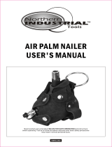
KNOW YOUR FRAMING NAILER
Carefully unpack the nailer and all its parts. Check all components and compare against the graph below. If any part
is damaged or missing, please contact our customer service at (800) 232-1195, M-F 8-5 CST or email us at techsup-
7
Adjustable Exhaust
Trigger
Safety Bracket
With Non-Marring Tip
Depth Lock Screw
1/4˝ NPT
Air Inlet
Magazine
Lock
Nail-Loading Slot
Magazine
Nail Feeder Shoe
PACKAGE CONTENT QTY
Blow Mold Case 1
Framing Nailer 1
Hex Key 4
Contact Trigger 1
Air Tool Lubricating Oil 1
Instruction Manual 1

PREPARATION AND ADJUSTMENTS
LUBRICATING THE TOOL (Fig. 1)
This tool requires lubrication before each use (especially the first use). Proper lubrication is the owner’s responsibil-
ity. Failure to lubricate the tool properly will dramatically shorten the life of the tool and void the warranty.
Fig. 1
Oil
NOTE: An automatic in-line oiler is a convenient way to provide oil to
the tool. If an in-line oiler is installed, manual lubrication through the
air inlet is not required.
1. Make sure the tool is disconnected from the air supply before adding
lubricant.
2. Turn the tool so the air inlet is facing up. Place 4 to 5 drops of air tool
lubrication oil into the air inlet (Fig. 1). NOTE: Excessive lubrication
may damage the work surface. Wipe off any excess oil from the inlet.
CONNECTING THE TOOL TO AN AIR SUPPLY (Fig. 2)
Connect your tool to a properly installed compressed air supply. The working pressure of the air compressor must
be regulated by a regulator to fit the operating pressure of your nailer (70-120 PSI). All components including hoses,
connectors, filters, regulators, etc. must have a working pressure rating of at least 180 PSI. Refer to the diagram
below (Fig. 2) for the recommended accessories and connection order.
WARNING: Connect the air supply before loading fasteners. Make sure the nailer magazine is empty
when connecting to the air supply. Never aim the tip of the nailer towards yourself or others.
WARNING: Use only clean dry and regulated air. Never use oxygen combustible gases, bottled gases or
high pressure compressed gas to power this tool. Danger of explosion and/or serious personal injury may
result. Do not operate when the air pressure is outside of the operating pressure range.
1. Turn on the compressor on and set the regulator (Fig. 2 - Regulator) to the proper pressure within 70 to 120 PSI.
The pressure can be adjusted later depending on firing depth, the length of nails and the hardness of the workpiece.
2. Be sure the air hose is depressurized when installing or removing adapters to the air line. Connect the compressed
air hose to the inlet of your air compressor. Connect the other end of the air hose to the air inlet of the nailer. The
connections must click into place audibly. Use appropriate hose tape to prevent leaking.
3. To disconnect the tool from the air hose, pull back the ring on the quick connector to release the connection.
Repeat for disconnecting the air compressor from the air hose.
Fig. 2
8

ADJUSTING THE AIR OUTLET (Fig. 5)
Air will be released from the air outlet during operation. Rotate the ad-
justable air outlet cap (Fig. 5) on the top of the nailer to direct the re-
leased air to your preferred direction, away from yourself and others.
NON-MARRING TIP (Fig. 6)
The rubber non-marring tip (Fig. 6 - 1) is attached to the safety bracket
to reduce marring and damage to your workpiece during operation.
The non-marring tip can be removed from the safety bracket to increase
the driving depth and allow better grip on the surface using the no-slip
teeth (Fig. 6 - 2). However this may leave dents on your workpiece.
WARNING: Disconnect tool from air supply before remov-
ing or installing the non-marring tips.
To detach the non-marring tip, flip open the locking clip (Fig. 6 - 3) and
slide the non-mar tip off the safety bracket. To attach the non-marring
tip, slide it onto the safety bracket and secure it with the locking clip (Fig.
6 - 3).
Fig. 3
Fig. 5
Fig. 6
PREPARATION AND ADJUSTMENTS
LOADING THE FASTENERS (Fig. 3 & 4)
WARNING: Always load the fasteners after connect-
ing the tool to its air supply. Never aim the tip of the
nailer at a person or animal in case of misfire.
1. Slide the feeder shoe (Fig 3 - 2) all the way to the back of the
magazine until it click into place.
2. Place the fasteners into the magazine slot with the tip pointing
downwards. Slide the fasteners forward against the front of the
magazine.
Your nailer accepts 21-degree round head framing nails with di-
ameter ranging from 0.113" - 0.131" (2.87 - 3.33 mm) and length
ranging from 2" - 3-9/16" (50 - 90 mm). A maximum of 60 fasten-
ers may be loaded.
3. Pull the feeder shoe backwards, and press the magazine lock.
Release the feed shoe, allowing it to spring forward against the
nails to secure them in position. Check that the nails have been
loaded correctly and securely.
9
NOTE: The nailer is equipped with an anti-dry-fire mechanism to protect your nailer. When the quantity of fasten-
ers in the magazine drops below five, the nailer will not fire. Reload your magazine when the nail count gets low.
1
2
1
3
2
Fig. 4

TO CHANGE THE TRIGGER (Fig. 7)
WARNING: Disconnect the nailer from the air supply and
remove fasteners from magazine before making adjustments
to the tool.
1. Remove the o-ring on the side of the trigger pin. It may be easiest to
use tweezers, a paperclip, or other appropriate tool. Be careful to not
damage the O-ring.
2. Remove the trigger pin, the trigger and the trigger spring.
3. Swap the trigger switch out for the alternative trigger.
4. Replace the trigger spring, the trigger, the trigger pin and the o-ring.
TYPES OF TRIGGERS
Two different triggers are included with your nailer. Fully understand the characteristics and activation mode of each
trigger. Choose the suitable trigger that fits the task at hand.
Sequential Trigger (Black Trigger):
Your nailer is installed with the sequential trigger. With this trigger installed, the safety bracket needs to be activated
before pulling the trigger in order to drive a fastener. This trigger prevents the nailer from being able to bump fire,
which means you cannot hold down the trigger and press down on the safety bracket to fire multiple nails in a row.
This would be the preferred method for safer operation and more detailed and specific nailing jobs.
Contact Trigger (Red Trigger):
The contact trigger is provided as an accessory. Using this trigger, you can activate the safety bracket and trigger in
any sequence to drive a fastener. This trigger gives users the opportunity to both bump fire (where the trigger re-
mains engaged and the bumping of the safety bracket shoots nail after nail) and also sequential fire (where the safety
bracket remains engaged and the repetitive pulling of the trigger shoots nail after nail). Only one of the two safety
mechanisms (the trigger or the safety bracket) needs to be disengaged between firing multiple nails. This is best for
larger jobs where speed is more important than precision. However, there is also is a higher chance of misfiring
when the contact trigger is installed.
WARNING: There is a higher chance of misfiring when the contact trigger is installed. Never put your
finger on the trigger unless you are prepared for operation. Unintended nails can be discharged when the
trigger is engaged and the safety bracket is pressed by accident.
PREPARATION AND ADJUSTMENTS
WARNING: Before each use, check the nailer, compressed air connections and air lines. If any parts
are missing or damaged, do not operate this tool until the parts are repaired and replaced. Failure to do
so could possibly result in a serious personal injury.
10
Fig. 7
Trigger Spring
O-ring
Trigger
Trigger Pin
5. Check that the trigger mechanism works properly before connecting to the air supply.

ADJUSTING THE DRIVING DEPTH (Fig. 8)
Make sure to disconnect the air supply and remove fasteners from maga-
zine before making adjustments. The driving depth is set to the maximum
from the factory. Adjust the driving depth using the following steps.
1. Loosen the depth lock screw (Fig. 8 - 1) using the hex key.
2. Slide the safety bracket (Fig. 8 - 2) to adjust the firing depth. Sliding the
bracket upward increases the driving depth and sliding the bracket down-
ward decreases the driving depth. Retighten the depth lock screw.
NOTE: Adjust the air pressure regulator along with the depth setting so
that the desired driving depth can be achieved with the lowest possible air
OPERATION
WARNING: Hearing and eyes protection must be used
drive a fastener. Reposition the nailer and disengage either the trigger or the safety bracket between shooting mul-
tiple nails. NOTE: Unit may spark when nails are fired, this is normal.
WARNING: Do not fire another nail over the position of the existing nail, as the nail may bounce back
and cause serious injury.
4. The nailer is equipped with an anti-dry-fire mechanism to protect your nailer from firing blank shots. When the
remaining quantity of fasteners is less than five, reload the magazine according to “Loading the Fasteners” on page 9.
5. After operation, turn off the air compressor and depressurize the compressor according to the instructions in-
cluded with your compressor. Disconnect the air hose from the nailer.
1. Check that the air supply is correctly connected to the tool at
the correct pressure and the fasteners have been properly load-
ed into the magazine.
2. Hold the nailer upright on the workpiece and position the
safety bracket where the fastener will be driven (Fig. 8).
3. For Sequential Trigger: Press down the safety bracket and
pull the trigger to drive a fastener. Reposition the nailer and dis-
engage the trigger between shooting multiple nails.
For Contact Trigger: Press down the safety bracket and pull the
trigger or pull the trigger and press down the safety bracket to
11
Fig. 9
90°
Fig. 8
SHOOTING NAILS (Fig. 9)
WARNING: User must wear proper eye and hearing protection when operating this tool. Stay alert and
keep proper balance at all times. Keep your fingers away from the trigger when not operating the nailer
to reduce the risk of unintended nail discharge.
WARNING: Never attempt to drive a fastener into materials that is too hard, or at a steep angle, or near
the edge of the workpiece. The fastener can ricochet and cause serious personal injury.
pressure. This will save energy, reduce noise level and reduce the wear on the tool.
1
2

5. Connect the nailer to the air supply. Load the magazine and test fire a nail into a scrap piece of wood to confirm
the nailer is working properly again.
WARNING: If nails continue to jam, stop using the nailer. Contact our customer service at 800-232-1195
(M-F 8-5 CST).
1. Disconnect the nailer from the air supply
2. Pull the feeder shoe all the way to the back of the magazine until it
latches. Slide fasteners to the back and remove all remaining fasten-
ers from the magazine.
3. Use a pair of needle nose pliers or a flat head screwdriver to
remove the bent fastener from the back opening of the nosepiece
(Fig. 10 - 1). If the fastener cannot be removed directly, refer to the
following step to remove the magazine.
CLEARING JAMMED FASTENERS (Fig. 10 & 11)
WARNING: Disconnect air line from the tool and remove all fasteners before removing jammed nails to
avoid personal injury. Keep the tool pointed away from yourself and others.
1
2
Fig. 11
OPERATION
12
Fig. 10
1
4. Remove the four screws (Fig. 11 - 1 & Fig. 11 - 2) using the hex key and slide the magazine off the nosepiece.
Remove the bent fastener. Reattach the magazine and replace the four screws.

MAINTENANCE
WARNING: Disconnect tool from air supply and empty fasteners from the magazine before performing
any cleaning or maintenance.
LUBRICATION
Routine lubrication of the tool is required for best performance. An automatic in-line oiler is recommended. If tool
is used without an in-line oiler, place 2 drops of pneumatic tool oil into the air inlet of the tool at the beginning of
each workday or after about 1 hour of continuous use. Oil added through the air inlet will lubricate the internal
moving parts.
CLEANING
Keep the tool clean for better and safer performance. Wipe the tool clean with a damp towel and some soft soap.
Blow the tool clean using compressed air. Only use non-flammable cleaning solutions to wipe exterior of the tool as
necessary. CAUTION: Do not soak tool with cleaning solutions. Such solutions can damage internal parts.
INSPECTION
1. Inspect the trigger and safety mechanism to assure the system is complete and functional (no loose or missing
parts, no binding or sticking parts). Do not operate if any portion of the tool, trigger, or safety bracket is damaged,
inoperable, disconnected, or altered. Any issues with the tool such as leaking air, damaged parts, or missing parts
should be repaired or replaced before use.
2. Inspect the tool and make sure all screws are tight. Loose screws can cause personal injury or damage the tool.
3. All compressed air contains moisture and other contaminates that are detrimental to internal components of the
tool. Dirt and water in the air supply are major causes of pneumatic tool wear. Regularly drain water and contami-
nations out from the compressor. An air line filter is recommended to remove most of these contaminates and
prolong the life of the tool. Follow the compressor instructions to check the filter of the air compressor.
STORAGE
Place the tool and accessories inside the blow mold case to protect it from dust and moisture. Store the unit and
accessories in a dark, dry, frost-free and well ventilated place, out of the reach of children. The ideal storage tem-
perature is between 50 to 86°F (10 and 30°C).
PRODUCT DISPOSAL
Used pneumatic tools contain recyclable materials and should not be disposed with household waste. Please take
this product to your local recycling facility for responsible disposal and to minimize its environmental impact.
13

EXPLODED VIEW AND PARTS LIST
14

EXPLODED VIEW AND PARTS LIST
No. Part No. Description
1 61793-001 Screw
2 61793-002 Spring Washer
3 61793-003 Bushing
4 61793-004 Exhaust Cover
5 61793-005 Seal
6 61793-006 Screw
7 61793-007 Spring Washer
8 61793-008 Cylinder Cap
9 61793-009 Gasket
10 61793-010 Washer
11 61793-011 Valve Seat
12 61793-012 Spring
13 61793-013 O-ring
14 61793-014 O-ring
15 61793-015 Valve
16 61793-016 Screw
17 61793-017 Cylinder Seal
18 61793-018 Collar
19 61793-019 O-ring
20 61793-020 Piston Assembly
21 61793-021 Cylinder
22 61793-022 O-ring
23 61793-023 O-ring
24 61793-024 Restrictive Plate
25 61793-025 O-ring
26 61793-026 Bumper A
27 61793-027 Bumper B
28 61793-028 Body
29 61793-029 O-ring
30 61793-030 Nose
31 61793-031 Spring Washer
32 61793-032 Screw
33 61793-033 Spring
34 61793-034 Safety Bracket
35 61793-035 Screw
36 61793-036 Bushing
37 61793-037 Safety Nosepiece
38 61793-038 Washer
39 61793-039 Depth Adjustment
40 61793-040 Rubber Cover
41 61793-041 Spring Pin
42 61793-042 Safe Guide
No. Part No. Description
43 61793-043 O-ring
44 61793-044 O-ring
45 61793-045 Valve Set
46 61793-046 O-ring
47 61793-047 O-ring
48 61793-048 Trigger Valve Head
49 61793-049 O-ring
50 61793-050 Spring
51 61793-051 O-ring
52 61793-052 Trigger Valve Stem
53 61793-053 O-ring
54 61793-054 Trigger Valve Guide
55 61793-055 Spring
56 61793-056 Trigger Assembly
57 61793-057 Washer
58 61793-058 Pin
59 61793-059 Rail
60 61793-060 Washer
61 61793-061 Nut
62 61793-062 Washer
63 61793-063 Coil Spring Assembly
64 61793-064 Pin
65 61793-065 Bushing
66 61793-066 Screw
67 61793-067 Block
68 61793-068 Feed Shoe
69 61793-069 Screw
70 61793-070 Magazine
71 61793-071 Screw
72 61793-072 Support
73 61793-073 Nut
74 61793-074 Lock
75 61793-075 Torsion Spring
76 61793-076 Bushing
77 61793-077 Nut
78 61793-078 Nut
79 61793-079 Soft Grip Sleeve
80 61793-080 Gasket
81 61793-081 End Cap
82 61793-082 Screw
83 61793-083 Air Plug
15

TROUBLESHOOTING
WARNING: Stop using the tool immediately if any of the following problems occur or risk serious per-
sonal injury. Repairs and replacements should only be performed by authorized personnel. If you have
any questions, please contact our customer service at (800) 232-1195, M-F 8-5 CST.
Problem Common Causes Solution
Air leaking at trigger
area
1. O-ring in trigger valve is damaged.
2. Trigger valve head is damaged.
3. Trigger valve stem, seal or O-ring is
damaged.
1. Check and replace O-ring.
2. Check and replace trigger valve head.
3. Check and replace trigger valve stem,
seal or O-ring.
Air leaking between
body and drive guide
Damaged piston O-ring or bumper. Check and replace O-ring or bumper.
Air leaking between
body and cylinder
cap
1. Loose screw.
2. Damaged seal.
1. Tighten screws.
2. Check and replace seal.
Trigger is pressed
but no fastener is
driven.
1. Not properly connected to air supply.
2. Air hose is leaking.
3. Fasteners not installed correctly
4. Operating pressure too low.
1. Check air supply connections.
2. Check air hose for leaks.
3. Load fasteners into the magazine cor-
rectly.
4. Increase operating pressure.
Fasteners are driven
too deep
1. Worn bumper.
2. Air pressure is too high.
3. The depth setting is too shallow.
1. Replace bumper.
2. Adjust the air pressure.
3. Adjust the depth wheel.
Runs slowly or has
power loss
1. Insufficient oil.
2. Insufficient air supply.
3. Broken spring in cylinder cap.
4. Exhaust port in cylinder cap is blocked.
1. Lubricate as instructed.
2. Check air supply.
3. Replace spring.
4. Replace damaged internal parts.
Tool skips a fastener
1. Worn bumper or damaged spring.
2. Dirt in drive guide.
3. Inadequate airflow to tool.
4. Worn or dry O-ring on piston.
5. Damaged O-ring on trigger valve.
6. Cylinder cap seal leaking.
1. Replace bumper or pusher spring.
2. Clean drive channel of front plate.
3. Check hose and compressor fittings.
4. Replace O-ring or lubricate.
5. Replace O-ring.
6. Replace seal.
Fasteners repeatedly
jam
1. Joint guide is worn.
2. Fasteners are wrong size or damaged.
3. Magazine or front plate screws are
loose.
4. Piston assembly is damaged.
1. Replace joint guide.
2. Use the recommended and undamaged
fasteners.
3. Tighten screws.
4. Replace piston assembly.
Tool will not drive
down tight
1. Piston assembly is damaged.
2. Insufficient air pressure.
3. Slow cycling and loss of power.
1. Replace piston assembly.
2. Adjust to adequate air pressure.
3. Check cylinder cap spring for broken
coils or reduced length. Check if exhaust
port of cylinder cap is restricted.
16

LIMITED TWO YEAR WARRANTY
WEN Products is committed to build tools that are dependable for years. Our warranties are consistent with this
commitment and our dedication to quality.
LIMITED WARRANTY OF WEN CONSUMER POWER TOOLS PRODUCTS FOR HOME USE
GREAT LAKES TECHNOLOGIES, LLC (“Seller”) warrants to the original purchaser only, that all WEN con-
sumer power tools will be free from defects in material or workmanship for a period of two (2) years from date of
purchase. Ninety days for all WEN products, if the tool is used for professional use.
SELLER’S SOLE OBLIGATION AND YOUR EXCLUSIVE REMEDY under this Limited Warranty and, to
the extent permitted by law, any warranty or condition implied by law, shall be the repair or replacement of parts,
without charge, which are defective in material or workmanship and which have not been misused, carelessly
handled, or misrepaired by persons other than Seller or Authorized Service Center. To make a claim under this
Limited Warranty, you must make sure to keep a copy of your proof of purchase that clearly defines the Date of
Purchase (month and year) and the Place of Purchase. Place of purchase must be a direct vendor of Great Lakes
Technologies, LLC. Third party vendors such as garage sales, pawn shops, resale shops, or any other secondhand
merchant void the warranty included with this product. Contact [email protected] or 1-800-232-
1195 to make arrangements for repairs and transportation.
When returning a product for warranty service, the shipping charges must be prepaid by the purchaser. The prod-
uct must be shipped in its original container (or an equivalent), properly packed to withstand the hazards of ship-
ment. The product must be fully insured with a copy of the warranty card and/or the proof of purchase enclosed.
There must also be a description of the problem in order to help our repairs department diagnose and fix the
issue. Repairs will be made and the product will be returned and shipped back to the purchaser at no charge.
THIS LIMITED WARRANTY DOES NOT APPLY TO ACCESSORY ITEMS THAT WEAR OUT FROM
REGULAR USAGE OVER TIME INCLUDING BELTS, BRUSHES, BLADES, ETC.
ANY IMPLIED WARRANTIES SHALL BE LIMITED IN DURATION TO TWO (2) YEAR FROM
DATE OF PURCHASE. SOME STATES IN THE U.S., SOME CANADIAN PROVINCES DO NOT AL-
LOW LIMITATIONS ON HOW LONG AN IMPLIED WARRANTY LASTS, SO THE ABOVE LIMITA-
TION MAY NOT APPLY TO YOU.
IN NO EVENT SHALL SELLER BE LIABLE FOR ANY INCIDENTAL OR CONSEQUENTIAL DAM-
AGES (INCLUDING BUT NOT LIMITED TO LIABILITY FOR LOSS OF PROFITS) ARISING FROM
THE SALE OR USE OF THIS PRODUCT. SOME STATES IN THE U.S. AND SOME CANADIAN
PROVINCES DO NOT ALLOW THE EXCLUSION OR LIMITATION OF INCIDENTAL OR CON-
SEQUENTIAL DAMAGES, SO THE ABOVE LIMITATION OR EXCLUSION MAY NOT APPLY TO
YOU.
THIS LIMITED WARRANTY GIVES YOU SPECIFIC LEGAL RIGHTS, AND YOU MAY ALSO HAVE
OTHER RIGHTS WHICH VARY FROM STATE TO STATE IN THE U.S., PROVINCE TO PROVINCE
IN CANADA AND FROM COUNTRY TO COUNTRY.
THIS LIMITED WARRANTY APPLIES ONLY TO PORTABLE ELECTRIC TOOLS, BENCH POW-
ER TOOLS, OUTDOOR POWER EQUIPMENT AND PNEUMATIC TOOLS SOLD WITHIN THE
UNITED STATES OF AMERICA, CANADA AND THE COMMONWEALTH OF PUERTO RICO. FOR
WARRANTY COVERAGE WITHIN OTHER COUNTRIES, CONTACT THE WEN CUSTOMER SUP-
PORT LINE.
17

THANKS FOR
REMEMBERING
/