Página 5
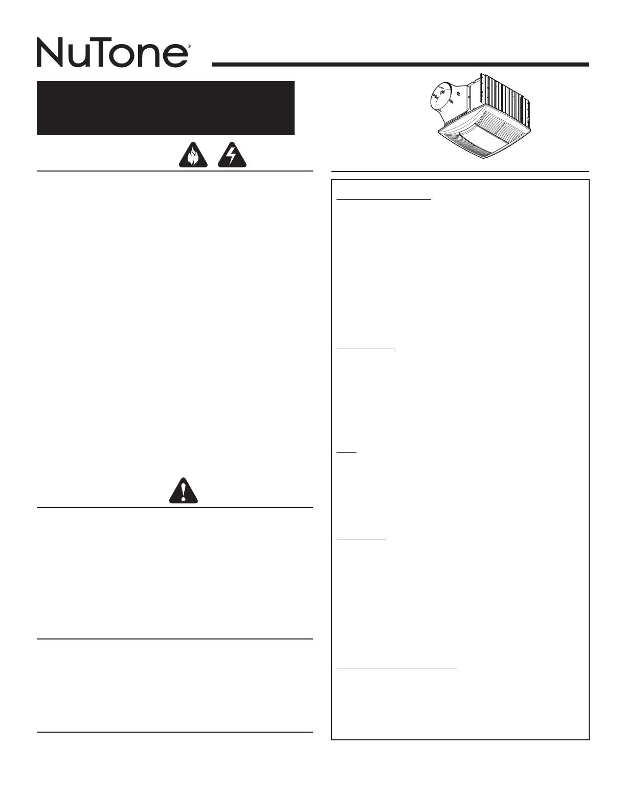
VENTILADOR / LUZ MODELO QTN130LE1
ADVERTENCIA
PARA REDUCIR EL RIESGO DE INCENDIOS, DESCARGAS ELÉCTRICAS O
LESIONES PERSONALES, OBSERVE LAS SIGUIENTES PRECAUCIONES:
1. Use la unidad sólo de la manera indicada por el fabricante. Si tiene preguntas,
comuníquese con el fabricante a la dirección o al número telefónico que se
incluyen en la garantía.
2. Antes de dar servicio a la unidad o de limpiarla, interrumpa el suministro
eléctrico en el panel de servicio y bloquee los medios de desconexión del
servicio para evitar que la electricidad se reanude accidentalmente. Cuando
no sea posible bloquear los medios de desconexión del servicio, fije firme-
mente un dispositivo de advertencia (por ejemplo, una etiqueta) en un lugar
prominente del panel de servicio.
3. El trabajo de instalación y el cableado eléctrico deben ser realizados por
una o más personas calificadas, y deben cumplir con todos los códigos y
normas correspondientes, incluidos los códigos y normas de construcción
específicos de protección contra incendios.
4. Se necesita suficiente aire para que se lleve a cabo una combustión adec-
uada y para la descarga de los gases a través del tubo de humos (chimenea)
del equipo quemador de combustible, a fin de evitar las contracorrientes.
Siga las directrices y normas de seguridad del fabricante del equipo de
calentamiento, tales como las publicadas por la Asociación Nacional de
Protección contra Incendios (National Fire Protection Association, NFPA),
la Sociedad Americana de Ingenieros de Calefacción, Refrigeración y Aire
Acondicionado (American Society for Heating, Refrigeration and Air Condi-
tioning Engineers, ASHRAE) y las autoridades de los códigos locales.
5. Al cortar o perforar a través de la pared o del cielo raso, no dañe el cableado
eléctrico ni otros servicios ocultos.
6. Los ventiladores con conductos deben siempre conectarse hacia el exterior.
7. Es aceptable utilizar este producto sobre una regadera o tina si se conecta
a un circuito secundario protegido por un GFCI (interruptor accionado por
pérdida de conexión a tierra) (instalación del techo solamente).
8. Esta unidad debe conectarse a tierra.
PRECAUCIÓN
1. Sólo para usarlo en ventilación general. No lo use para descargar materiales
ni vapores peligrosos o explosivos.
2. Este producto se diseña para la instalación en techos hasta una echada
de 12/12 (ángulo de 45 grados). NO MONTE ESTE PRODUCTO EN UNA
TECHO.
3. Para evitar daños a los cojinetes del motor y rotores ruidosos y/o no equilib-
rados, mantenga la unidad de accionamiento al resguardo de rocío de yeso,
polvo de la construcción, etc.
4. Lea la etiqueta de especificaciones del producto para ver información y
requisitos adicionales.
LEA Y CONSERVE ESTAS
INSTRUCCIONES
GARANTÍA
A la persona que realiza la instalación:
Deje este manual con el dueño de la casa.
OPERACIÓN
LIMPIEZA Y MANTENIMIENTO
Para lograr un funcionamiento silencioso y eficiente, como también larga vida
y una apariencia atractiva, baje o retire la rejilla y aspire el interior de la unidad
con el accesorio del cepillo para sacudir polvo.
El motor está permanentemente lubricado y nunca necesitará aceite. Si los
cojinetes del motor están haciendo ruido excesivo o inusual, reemplace el
conjunto del ventilador (incluye el motor y el rodete del ventilador).
Opere este ventilador mediante un interruptor de encendido/apagado o control
de velocidad de estado sólido. Vea los detalles en la sección “Conexión eléctrica”.
El uso de los controles de la velocidad con excepción de los modelos 78V y
78W de Broan puede causar un ruido del tarareo del motor.
Para registrar este
producto visite:
www.nutone.com/register
Garantía limitada
Periodo y exclusiones de la garantía: Broan-NuTone LLC (la “Compañía”) garantiza al consumidor
comprador original de su producto (“usted”) que el producto (el “Producto”) estará libre de defectos en
materiales o en mano de obra, por un periodo de tres (3) años a partir de la fecha de compra original.
El periodo de garantía limitada para cualquier pieza de repuesto proporcionada por la compañía y para
cualquier Producto reparado o reemplazado bajo esta garantía limitada debe ser lo que reste del periodo
de garantía original.
Esta garantía no cubre controles de velocidad, arrancadores de lámparas fluorescentes, tubos, bombillas de
halógeno e incandescentes, fusibles, filtros, conductos, tapas de techo, tapas de pared ni otros accesorios
que pudieran ser comprados por separado e instalados con el producto. Esta garantía tampoco cubre (a)
mantenimiento y servicio normal, (b) uso y desgaste normal, (c) Productos o piezas sujetos a mal uso,
abuso, uso anormal, negligencia, accidente, mantenimiento inadecuado o insuficiente, almacenamiento
o reparación (que no sea reparación por parte de la Compañía), (d) daños causados por instalación
defectuosa, o bien instalación o uso contrario a las recomendaciones o instrucciones, (e) cualquier
Producto que se haya movido de su punto de instalación original, (f) daños ocasionados por el medio
ambiente o los elementos naturales, (g) daños en tránsito, (h) desgaste natural del acabado, (i) Productos
en uso comercial o no residencial, o (j) daños ocasionados por incendio, inundación u otro caso fortuito.
Esta garantía cubre solamente Productos vendidos a clientes originales en los Estados Unidos por la
Compañía o a distribuidores de EE. UU. autorizados por la Compañía.
Esta garantía sustituye todas las garantías anteriores y no es transferible del comprador consumidor
original.
No hay otras garantías: Esta garantía limitada contiene la única obligación de la Compañía y su único
recurso ante productos defectuosos. Las garantías anteriores son exclusivas y en lugar de cualquier otra
garantía, expresa o implícita. LA COMPAÑÍA NIEGA Y EXCLUYE CUALQUIER OTRA GARANTÍA EXPRESA,
Y NIEGA Y EXCLUYE TODAS LAS GARANTÍAS IMPLÍCITAS POR LEY, INCLUYENDO, ENTRE OTRAS,
LAS DE COMERCIALIZACIÓN Y APTITUD PARA UN PROPÓSITO EN PARTICULAR. Hasta el grado en que
la ley aplicable prohíba la exclusión de las garantías implícitas, la duración de cualquier garantía implícita
aplicable está limitada al periodo especificado para la garantía expresa antes mencionada. Algunos estados
no permiten limitaciones en la duración de una garantía implícita, así que la limitación anterior tal vez
no aplique en su caso. Cualquier descripción verbal o escrita del Producto es para el único propósito de
identificarlo y no deberá considerarse como una garantía expresa.
Siempre que sea posible, toda disposición de esta garantía limitada deberá ser interpretada de tal forma
que sea efectiva y válida de conformidad con la ley aplicable, pero si alguna disposición fuera considerada
prohibida o inválida, quedará sin efecto solo en virtud de dicha prohibición o invalidez, sin invalidar el resto
de dicha disposición o las demás disposiciones restantes de la garantía limitada.
Recurso: Durante el periodo de garantía limitada aplicable, la Compañía, a su opción, suministrará piezas de
repuesto, o reparará o reemplazará, sin cargo alguno, cualquier Producto o pieza del mismo, hasta el grado
en que la Compañía lo encuentre cubierto bajo esta garantía limitada y en incumplimiento de la misma en
condiciones normales de uso y servicio. La Compañía le enviará el Producto reparado o reemplazado o las
piezas de repuesto sin cargo. Usted es responsable de todos los costos de retiro, reinstalación y envío,
seguro u otros cargos de flete incurridos en el envío del Producto o pieza a la Compañía. Si debe enviar
el Producto o la pieza a la Compañía, tal como lo indique la Compañía, debe empaquetar adecuadamente
el Producto o la pieza: la Compañía no se hace responsable por los daños en tránsito. La Compañía se
reserva el derecho de utilizar Productos o piezas reacondicionados, renovados, reparados o refabricados
en el proceso de reemplazo o reparación de garantía. Dichos Productos y piezas serán comparables en
función y desempeño a un Producto o una pieza original y tendrán garantía durante el resto del periodo
de la garantía original.
Exclusión de daños: LA OBLIGACIÓN DE LA COMPAÑÍA DE SUMINISTRAR PIEZAS DE REPUESTO, O
DE REPARAR O REEMPLAZAR, A OPCIÓN DE LA COMPAÑÍA, SERÁ SU ÚNICO Y EXCLUSIVO RECURSO
BAJO ESTA GARANTÍA LIMITADA, Y LA ÚNICA Y EXCLUSIVA OBLIGACIÓN DE LA COMPAÑÍA. LA
COMPAÑÍA NO SERÁ RESPONSABLE POR DAÑOS INCIDENTALES, INDIRECTOS, RESULTANTES O
ESPECIALES QUE SURJAN POR EL USO O DESEMPEÑO DEL PRODUCTO, O EN RELACIÓN CON EL
MISMO.
Algunos estados no permiten la exclusión o limitación de daños incidentales o resultantes, por lo que
la limitación antes mencionada podría no aplicarse a usted. Esta garantía le otorga derechos legales
específicos, y usted podría tener otros derechos que varían de un estado a otro.
Esta garantía cubre únicamente el reemplazo o la reparación de Productos defectuosos o piezas de los
mismos en la planta principal de la Compañía, y no incluye el costo del viaje para el servicio de campo ni
los viáticos.
Cualquier asistencia que proporcione o procure la Compañía para usted fuera de los términos, limitaciones
o exclusiones de esta garantía limitada no constituirá una renuncia a dichos términos, limitaciones o
exclusiones, ni dicha asistencia extenderá o renovará la garantía.
La Compañía no le reembolsará ningún gasto en el que usted haya incurrido al reparar o reemplazar
cualquier Producto defectuoso, excepto los incurridos con el permiso previo por escrito de la Compañía.
Cómo obtener el servicio cubierto por la garantía: Para tener derecho al servicio cubierto por la garantía,
usted debe (a) notificar a la Compañía a la dirección o número de teléfono que aparecen abajo en un plazo
de siete (7) días después de descubrir el defecto cubierto, (b) proporcionar el número de modelo y la
identificación de la pieza y (c) describir la naturaleza de cualquier defecto en el Producto o la pieza. En el
momento de solicitar el servicio cubierto por la garantía, debe presentar un comprobante de la fecha de
compra original. Si usted no puede presentar una copia de la garantía limitada original por escrito, entonces
regirán los términos de la garantía limitada por escrito más actualizada de la compañía para su producto
en particular. Las garantías limitadas por escrito más actualizadas para los productos de la Compañía se
pueden encontrar en www.broan.com.
Broan-NuTone LLC 926 West State Street, Hartford, WI 53027
www.nutone.com 888-336-6151


