Gossen MetraWatt SECUTEST SIII Operating instructions

Category
Measuring, testing & control
Type
Operating instructions
SECUTEST
®
SIII
Test Instrument for Testing the Electrical Safety of Electrical Devices
3-349-111-03
10/5.06
Operating Instructions
2 GMC-I Gossen-Metrawatt GmbH
1
2
3
45678910
11
12
13
14 15 1816 17
N
L
PROBERS232 5 4
Auto
PE
3
2
SECUTEST SIII
HV
Function
Test
V
Aux
Setup
Iso
/
Safety Test
I leakage
BDFHK
AC E G I
Applied Parts
1
These operating instructions describe
an instrument with firmware version
62x.
Note
Contact problems with exposed conductive parts
when using the standard probe with test tip
In order to assure good contact, surface
coatings must be removed from devices
under test with special tools at a suitable
location so that the surface has a metallic
shine.
The tip of the test probe is not suitable for
scratching away paint, because this may
impair its coating and/or mechanical
strength.
The brush probe may be more suitable than
the test probe in certain individual cases.
24
23
22
21
25
22
26
27
19
GMC-I Gossen-Metrawatt GmbH 3
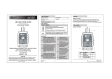
1 Jack for protective conductor at device under test
2 Jack for neutral conductor at device under test
3 Jack for phase conductor at device under test
4 Jack for connecting the probe
5 Jack for connecting the probe
6 Function selector switch
– Function Test: Function test
– Auto: Automatic test sequence according to selected standard
– PE: Protective conductor test
– Iso/HV: Insulation test / high-voltage test
– I leakage: Leakage current measurement
– V Ω: Multimeter functions
– Aux: Auxiliary multimeter functions
– Setup: Device configuration
7 scroll key for menu and parameter selection
8 scroll key for menu and parameter selection
9LCD window
10 Socket connector for RS 232 interface
11 Signal lamp for mains connection error
12 key for entry and for starting test sequences and finger contact
13 help key (context sensitive)
14 Key next to the symbol for switching test voltage to
the test socket (only possible if symbol LED is blinking)
15 Signal lamp for the functions text
16 Functional earth (equipotential bonding), feature J01
17 Operational earth, feature J01
18 Connector jacks for application parts, feature J01
19 Push-buttons (left and right) for releasing the handle from its snap-in position
20 Earthing contact socket for service purposes (feature B01),
e.g. for connecting a notebook or an A4 format printer
21 Standard outlet socket (test socket) for connecting the device under test
22 Push-buttons (left and right) for releasing the lid
23 Lid
24 Compartment for probe and accessories
25 Cover or printer module (feature E01)
26 Carrying handle and tilt stand
27 Test probe
Overview of Available Probe Types
1)
Accessory
Note
when using other probes than those specified above
The cables plugged into the sockets (4 and 5) must be short
circuited for testing with the probe, i.e. by plugging the ends of
the cable together, or via a conductive surface at the device
under test (4-wire measurement).
Remove any corrosion from the device under test.
Data Security
Measurement data, report data and user entries are stored to RAM at the
SECUTEST
®
PSI printer module (feature E01), as long as the respective
battery supplies the required amount of voltage.
Save your data to a PC on a regular basis in order to prevent any loss of
data at the printer module.
We assume no liability for data loss.
We recommend the following PC programs for data processing and data
management:
PS3 (transmission of measurement data to a PC, documentation,
management, report generating and deadline follow-up)
SECU 601 (program for activating the data base function in the
instrument (DBmed option), if not already available as a feature)
PC.doc-WORD (report and list generation
PC.doc-ACCESS (test data management)
i
Probe Type Application Special Features
Standard probe (test probe with coil-cable
and alligator clip)
Max. test current: 25 A none
SK2
1)
Max. test current: 25 A Probe with cable (no coil-cable),
2 meters long
Option SK5
(feature KD01 or accessory)
Restriction with fea-
ture G01 (I
K
>25A):
short-circuit current
<25A
Special probe in combination
with “automatic recognition of
measuring point change”
function (see chapter 18)
Brush probe
1)
Can be plugged onto all above listed
probes and test probes
Leakage current,
protective conductor
resistance
For contacting devices under
test with rotating, vibrating,
exposed conductive parts
!
Contents Page Contents Page
4 GMC-I Gossen-Metrawatt GmbH
1 Applications ...................................................................................6
1.1 Table: Types of DUTs – Tests – Regulations ...................................................6
1.2 Table: Individual Measurements and Regulations .............................................7
1.3 Table: Leakage Current Types ........................................................................7
1.4 List of Possible Options for SECUTEST
®
SIII Device Series ................................8
2 Safety Features and Precautions ...................................................9
2.1 Notes Regarding the High-Voltage Test .........................................................10
3 Initial Start-Up ..............................................................................10
3.1 Connection to the Mains (115 V / 230 V, 50 Hz / 60 Hz) ................................10
3.2 Automatic Recognition of Mains Connection Errors ........................................11
4 General Notes ..............................................................................11
4.1 Online Instructions .......................................................................................11
4.1.1 Automatic Safety Class Selection ..................................................................11
4.1.2 Manual or Automatic Operating Sequences ...................................................11
4.2 Online Help .................................................................................................11
4.3 Adjusting Contrast .......................................................................................12
4.4 Configuring Device Parameters, Setting Date and Time ..................................12
4.5 Configuring Measurement and Sequence Parameters ....................................12
4.6 Setting Limit Values .....................................................................................12
4.7 Saving the Settings ......................................................................................12
5 Classification of Devices Under Test ............................................13
5.1 Safety Classes ............................................................................................13
5.2 Application Parts (electrical medical devices) .................................................13
6 Abbreviations ...............................................................................14
7 Connecting the Device Under Test ...............................................15
8 Configuring Device Parameters ...................................................16
9 Measuring Protective Conductor Resistance ...............................17
9.1 Maximum Allowable Limit Values for Protective Conductor Resistance
for Connector Cables with a Length of up to 5 m ........................................... 18
10 Insulation Measurement ..............................................................18
10.1 Insulation Resistance R
ISO
. .......................................................................... 18
10.2 Equivalent Leakage Current ......................................................................... 20
10.3 High-Voltage Test .......................................................................................22
11 Leakage Current Measurement ...................................................23
11.1 Earth Leakage Current I
PE
(feature KA01 or SECU 601 option) ....................... 24
11.2 Housing Leakage Current I
HL
(probe current, contact current) ........................ 24
11.3 Patient Leakage Current I
PL ............................................................................................
24
11.4 Patient Auxiliary Current I
PX
(feature KA01 or SECU 601 option) ..................... 24
11.5 Residual Current I
RC .........................................................................................................
25
11.6 Device Leakage Current I
LC
per DIN VDE 0751 .............................................. 25
12 Multimeter Functions ...................................................................26
12.1 Probe Voltage U
probe
– Max. 300 V .............................................................. 26
12.2 Alternating / Direct Voltage U
AC/DC
– Max. 253 V (option*) ............................. 26
12.3 Resistance R (option*) ................................................................................. 26
13 Measurements with Accessories .................................................27
13.1 Alternating Current I
Z
with Clip-On Converter ................................................ 27
13.2 Protective Conductor Resistance R
PE
via Clip-On Meter ................................. 27
13.3 Temperature T with Pt100/1000 Sensor (option*) ......................................... 28
14 Function Test ...............................................................................29
GMC-I Gossen-Metrawatt GmbH 5
Contents Page Contents Page
15 Measurements in Accordance with National and
International Standards with Selector Switch in Auto Position ... 31
15.1 Test Sequences ...........................................................................................31
15.2 Setting Up Test Sequences ..........................................................................32
15.3 Configuring Measuring Parameters ...............................................................33
15.4 Testing Devices in Accordance with DIN VDE 0701, Parts 1, 200 and 260 ......34
15.5 Testing Devices in Accordance with DIN VDE 0701, part 240 .........................36
15.6 Testing Devices in Accordance with DIN VDE 0702:2004 ...............................38
15.7 Testing Extension Cables for VDE 0701, Part 1, and VDE 0702
(optional EL1 adapter) ..................................................................................41
15.8 Testing Multiple Outlets for VDE 0702 (optional EL1 adapter) .........................41
15.9 Testing in Accordance with the British Standard ............................................42
15.10 Testing in Accordance with DIN EN 60950 ....................................................44
15.11 Testing Devices in Accordance with EN 61010 .............................................46
15.12 Testing Devices in Accordance with EN 60335 .............................................48
15.13 Testing in Accordance with DIN VDE 0751 ....................................................50
15.14 Testing in Accordance with EN 60601 (feature KA01 or SECU 601 option) ......52
16 Storing in PSI Module (Feature E01)
and Database Operations (Feature KB01 or DBmed option) ........54
16.1 Storing Measurement Data in the PSI Module ................................................54
16.2 Database Operations ...................................................................................54
16.2.1 Setting Up Test Sequences with PC Software
(not for EN 60950, EN 61010, EN 60335) ...................................................54
16.2.2 Storing Test Results to the SECUTEST
®
SIII.....................................................54
17 Modem Operation (feature KC01 or DFÜmed option) .................. 55
18 Remote Control (feature KD01 or SK5 option) ............................. 55
19 Printing via PSI Module (Feature E01)
or with the Printer Adapter (Accessory Equipment DA-II) ........... 56
19.1 Print Out Test Data at the PSI Module ...........................................................56
19.2 Printing Test Results in Report Form .............................................................56
20 Direct Print-Out (feature KE01, option SECU-dd) ........................ 57
21 Characteristic Values .................................................................. 58
22 RS 232 Interface .......................................................................... 62
22.1 Transmission of Measurement Results to the SECUTEST
®
PSI ........................62
22.2 PC Connection ............................................................................................62
22.2.1 Software Evaluation of Measurement Results ................................................62
22.2.2 Instrument Control via Interface Commands ..................................................62
22.3 Interface Definition and Protocol ...................................................................62
23 Appendix ..................................................................................... 63
23.1 Evaluation of Measured Values for Individual Measurements
as well as for Calculated Quantities ..............................................................63
23.2 Evaluation of Measured Values during Equivalent Leakage Current
Measurement (Automatic Test Sequence According to Standard) ...................63
23.3 Index ..........................................................................................................64
24 Maintenance - Calibration ........................................................... 66
25 Repair and Replacement Parts Service
DKD Calibration Lab and Rental Instrument Service ................... 67
26 Product Support .......................................................................... 67
Condensed instructions for PS3 software for maintenance and equipment
management are provided with the PS3 CD ROM.
They include important instructions regarding the following topics:
PS3 demo with additional instructions
Special features for reading measured values in from a data file
6 GMC-I Gossen-Metrawatt GmbH
1 Applications
1.1 Table: Types of DUTs – Tests – Regulations
Attention!
!
The test instrument may not be used for measurements
within electrical systems!
Applicable Standards
Start-up
and Modifi-
cations
Testing after
Repairs
Periodic Testing
Type Tests /
Routine Testing
Devices under test
to be tested in
accordance with the
following regulations
DIN VDE 0751:2001
DIN VDE 0701 Part 1:2000
DIN VDE 0701 Part 240
DIN VDE 0751:2001
IEC 60601/DIN EN 60601
DIN VDE 0702:2004
British Standard
DIN VDE 0751:2001
IEC 60601/DIN EN 60601
DIN EN 60950/50116
DIN EN 61010
DIN EN 60335/50106
IEC 60601/DIN EN 60601
Laboratory instruments ••
Measuring and control
instruments
••••
Voltage generation
devices
••
Electric tools ••
Electric heating devices ••
Electric motor devices ••
Lamps ••
Devices for entertain-
ment electronics,
information and com-
munications technology
••
Cable reel, extension
and connection leads
••
Data processing and
office equipment
••
Electrical medical de-
vices, application parts
••
German National European International
DINEN61010 EN 61010 IEC 61010
DINEN60601 EN 60601 IEC 60601
DINEN60335-1 EN 60335-1 IEC 60335-1
DINEN60950 EN 60950 IEC 60950
GMC-I Gossen-Metrawatt GmbH 7
1.2 Table: Individual Measurements and Regulations
Key
Required test
1.3 Table: Leakage Current Types
Key
NC = normal condition
PAP = patient application part
PE = Potential earthing
, system protective conductor
PC = Protective conductor of the DUT
Individual
Measurements per
Regulation
Test current [A]
DIN VDE 0701
Part 1
DIN VDE 0701
Part 240
DIN VDE 0702
British Standard
DIN EN 60950
DIN EN 61010
DIN EN 60335
DIN VDE 0751
IEC 601/EN 60601
Protective
Conductor
Resistance
0,2 ••••
10 ••
25 •••••
Insulation
Resistance
••
Equivalent Leakage
Current
•••
Equivalent (Device)
Leakage Current
••
Equivalent Patient
Leakage Current
Residual Current
••
Device Leakage
Current
Earth Leakage
Current
Contact Current
••
Absence of Voltage
(exposed
conductive parts)
Housing Leakage
Current
••
Patient Leakage
Current
Patient Auxiliary
Current
High-Voltage Test •••• AC
Single Fault Conditions N
PC
Mains at Application Part
••
DIN VDE 0701-1 DIN VDE 0702-1 DIN VDE 0751-1
(2001)
DINEN60601-1 The following is
measured:
Equivalent
Leakage Current
Equivalent
Leakage Current
PROBE
(connected to
protective
conductor)
to L & N
Equivalent
Device Leakage
Current
I
EL
interrupted
from N
PROBE
(connected to
protective
conductor)
to L & N
Equivalent
Patient Leakage
Current
L & N & PE to
Patient Jacks
Contact Current/
Measurement for
Absence of
Voltage
Contact Current/
Measurement for
Absence of
Voltage
Housing Leakage
Current
NC
Probe to PE
Patient Leakage
Current
NC
Patient Leakage
Current
NC
Patient Jack to PE
Patient Auxiliary
Current
NC
Patient Jack to
Patient Jack
Earth Leakage
Current
NC
Protective
Conductor to PE
Device Leakage
Current during
Operation, Direct
Measurement
Protective
Conductor
Interrupted, Probe
+ PAP to PE
Protective
Conductor
Current with
Differential
Current
Measurement
Protective
Conductor
Current with
Differential
Current
Measurement
Device Leakage
Current during
Operation, with
Differential
Current
Measurement
See chapter 11.5
8 GMC-I Gossen-Metrawatt GmbH
1.4 List of Possible Options for SECUTEST
®
SIII Device Series
1)
Each measured value is documented in this case, as opposed to the results of a
test sequence for which the poorest value for each given test is displayed.
2)
Adapter set for international use (feature B01 included)
3)
Standard, not dependent upon feature designation
4)
The combination of features F02 and B04 or B07 is not possible.
Example of complete type designation (article number) for SECUTEST
®
SIII:
M7010 B01 E01 KD01 KE01 (only the designation of the basic instrument,
i.e. M7010, and entries which deviate from 00 are required)
5)
configured for hospital beds of safety class 2 (preset)
Feature
Design
Mains Connection for
Respective Country
User Interface
Language
Configuration
(settings in the setup menu)
Printer Module
SECUTEST
®
PSI
High-Voltage Testing
HV-DC
AC Test Current 50/60 Hz for
Protective Conductor
Measurement
DC Test Current for Protective
Conductor Measurement
including
Patient Ports
Measurements per EN 60601
SECU 601 Option (Z853G)
Database
DBmed Option (Z853H)
Modem Operation
DFÜmed Option (Z853K)
Remote Control
SC5 Special Cable (Z745K)
Direct Printing after each
Measurement for Automatic
Test Sequences
1)
,
Read-Out via RS 232
Calibration Certificate
in Accordance with DKD
ABCDEFGHJKAKBKCKDKEL
00 GMC D D GMC without without
10 A
3)
200 mA
3)
without without without without without without without
01 OEM
D
+ service
socket
GB OEM with
25 A with with with with with with
standard
version
02 UK GB F OEM
max.
6,126 kV DC
( 4KVAC)
4)
03 FI
04 IE
05 DK CZ
06 SA NL
07
Hospital
beds
5)
08 China/AUS
09 CH
11
Adapter set
2)
99
as
requested
GMC-I Gossen-Metrawatt GmbH 9
2 Safety Features and Precautions
This instrument fulfills the requirements of the applicable European and na-
tional EC guidelines. We confirm this with the CE marking. The relevant decla-
ration of conformity can be obtained from GMC-I Gossen-Metrawatt GmbH.
The SECUTEST
®
SIII test instrument has been manufactured and tested in
accordance with the following safety regulations:
IEC 61010-1 / DIN EN 61010-1 / VDE 0411-1, DIN VDE 0404,
DIN VDE 0413 Part 2 and 4
and DIN VDE 0104 (feature F02 only)
When used for its intended purpose, the safety of the user, the test instru-
ment and the device under test (electrical equipment or electrical medical
devices) is assured.
Read the operating instructions carefully and completely before placing your test
instrument into service, and follow all instructions contained therein. Make sure
that the operating instructions are available to all users of the instrument.
Tests may only be performed by a qualified electrician or under the supervision of
a qualified electrician. The user must be instructed by a qualified electrician
concerning performance and evaluation of the test.
Note
Manufacturers and importers of electrical medical devices must
provide documentation for the performance of maintenance by
trained personnel.
Observe the following safety precautions:
The instrument may only be connected to electrical systems with a
maximum of 230 V which are protected with a fuse or circuit breaker
with a maximum rating of 16 A.
Measurements within electrical systems are prohibited.
Be prepared for the occurrence of unexpected voltages at devices
under test (for example, capacitors can be dangerously charged).
Make certain that the measurement cables are in flawless condition,
e.g. no damage to insulation, no interruptions in cables or plugs etc.
Grip the test probe firmly, for example after insertion into a jack socket.
Tensioning at the coil cord may otherwise cause the test probe to snap
back resulting in possible injury.
Measurement of Insulation Resistance (equivalent leakage current)
This test is performed with a maximum voltage of 500 V, with a current
limit having been set (I < 10 mA). However, contacting the terminals
(L or N) causes an electric shock which, in turn, may result in accidents.
Leakage Current Measurement
During leakage current measurement it is imperative to ensure that the
device under test is operated at line voltage. Exposed conductive
parts may be charged with hazardous contact voltage during the test
and may consequently not be touched under any circumstances.
(There is a power shutdown as soon as the leakage current is higher than
approx. 10 mA).
Attention!
!
The function test may only be performed after the DUT has
successfully passed the safety test!
The measuring and test instrument may not be used:
If it demonstrates visible damage
With damaged connector cables, measuring cables or patient ports
If it no longer functions properly
After extraordinary stresses due to transport
In such cases, the instrument must be removed from operation and
secured against unintentional use.
Meanings of Symbols on the Instrument
The symbols on the instrument have the following meanings:
Warning regarding dangerous electrical voltage
Warning concerning a point of danger
(Attention: observe documentation!)
Test socket
Mark of approval from VDE test authority
Indicates EC conformity
This device may not be disposed of with the trash. For further
details on the WEEE marking, please refer to our website
www.gossenmetrawatt.com and enter search term ’WEEE’.
!
10 GMC-I Gossen-Metrawatt GmbH
2.1 Notes Regarding the High-Voltage Test
The KS13 cable set, or similar cable sets, may not be used for the high-voltage
test. The high-voltage test may only be performed directly via the test socket!
Attention!
!
Do not hold the device under test in your hand during testing,
especially when testing safety class II devices.
Make sure that the device under test does not make contact
with any equipment or persons during testing.
Liability Exclusion
In the event of sparkover, PCs operated in proximity to the test instrument may
“crash” resulting in data loss. All data and programs should be suitably backed up
before high-voltage testing is performed, and computers should be shut down if
necessary. A crash may occur even if no RS 232 connection has been established.
The manufacturer of the test instrument assumes no liability for direct or
consequential damage to computers, peripherals or data which occurs
during high-voltage testing.
The manufacturer assumes no liability for defects at the device under test
which result from high-voltage testing. As a rule, defects can only occur at
devices under test which are not in compliance with applicable standards,
which were previously damaged or which have been improperly repaired,
because high-voltage testing is required for type and routine testing by
IEC 61010-1/EN 61010-1 / VDE 0411, part 1, as well as EN 60335,
EN 60601 and EN 60950.
3 Initial Start-Up
3.1 Connection to the Mains (115 V / 230 V, 50 Hz / 60 Hz)
Connect the mains plug at the test instrument to the mains power
outlet. The function selector switch can be set to any position.
If a mains outlet (earthing contact outlet) is not available, or if only a
3-phase outlet is available, the adapter socket can be used to connect
the phase conductor, the neutral conductor and the protective
conductor. The adapter socket has three permanently attached
cables and is included with the KS13 cable set.
Attention!
!
If connection is not possible via an earthing contact outlet: Shut
down mains power first.
Then connect the cables from the coupling socket to the mains
using pick-off clips in accordance with the diagram.
Disconnection from mains power is only possible with the mains
plug.
L1
N
green-yellow
green-yellow
PE
L1
L2
L3
N
PE
L1
L2
L3
N
green-yellow
U
L–N
= 115 V / 230 V
Connection to the Mains
GMC-I Gossen-Metrawatt GmbH 11
3.2 Automatic Recognition of Mains Connection Errors
The test instrument automatically recognizes mains connection errors,
if the conditions in the following table have been fulfilled. The user is
informed of the type of error, and all measuring functions are disabled
in the event of danger.
1)
In SETUP – test sequence – IT system
Attention!
!
In either of the first two cases listed in the table above,
immediately disconnect the test instrument from the mains
and eliminate the error!
Note
Voltage at the electrical systems protective conductor PE may
result in distorted measurement values during testing for the
absence of voltage, or during leakage voltage measurements.
4 General Notes
4.1 Online Instructions
The performance of measurements and tests is quick and easy with the
SECUTEST
®
SIII. Integrated online instructions inform the operator regard-
ing all required connections, necessary work steps, operator errors, mea-
surement results and more in all measuring modes.
Information and test results appear at the dot matrix LCD in clear text.
4.1.1 Automatic Safety Class Selection
Depending upon the type of mains plug or the connection configuration
for the device under test, the test instrument recognizes the respective
safety class and recommends its use for the measurement to be
performed.
4.1.2 Manual or Automatic Operating Sequences
Depending upon selections made in the setup menu (selector switch in
the Auto position), the next measurement is started automatically after the
current measurement has been completed, or can only be started after
manual acknowledgement. The integrated online instructions are ade-
quate for most tests and measurements. However, the contents of these
operating instructions should nevertheless be read and observed.
4.2 Online Help
Online help can be queried and displayed at the LCD for all measuring
and test functions, and for almost all settings. Schematic diagrams which
illustrate proper connection of devices under test to the SECUTEST
®
SIII
can be displayed as well.
Press the following key in order to query online help:
Press the same key again in order to exit online help.
Note
Online help can be queried during measurement by pressing
and holding the help key.
Type of Mains
Connection Error
Message Condition Measurements
Voltage at protective
conductor PE to finger
contact
(key)
Text appears at
LCD
Press
key
U > 40 V
disabled
Protective conductor PE
and phase conductor L
reversed and/or
neutral conductor N
interrupted
lamp
lights up
Voltage at PE
>65V
impossible
(no supply power)
Contact voltage at
protective conductor PE
to neutral conductor N
or phase conductor L
Text appears at
LCD
U > 25 V
disabled, although
disabling can be
deactivated
1)
Mains voltage
too low lamp
lights up
U
L-N
< 90/180 V
possible
under certain
circumstances
!
!
12 GMC-I Gossen-Metrawatt GmbH
4.3 Adjusting Contrast
Set the selector switch to Auto.
Select the “Setup” menu, “return” is highlighted.
Activate contrast adjustment.
Press and hold the ENTER key.
Adjust contrast.
Return to the menu.
Store the contrast setting to permanent memory with the save function in
the setup menu.
4.4 Configuring Device Parameters, Setting Date and Time
Device parameters and functions which are valid for all selector switch
positions can be activated or deactivated with the selector switch in the
Setup position (see chapter 8 on page 16).
4.5 Configuring Measurement and Sequence Parameters
Measurement and sequence parameters, as well as functions, can be
activated or deactivated in the setup menu (selector switch in the Auto
position) for the respective test regulation. Refer to chapter 15.3 on page
33 for the significance of the various parameters.
4.6 Setting Limit Values
Upon delivery, the limit values set forth (at the point in time of issue)
in applicable national and international standards are stored to the test
instrument. Limit values for each of the respective standards can be
queried and changed if required with the setup menu (selector switch in
the Auto position), but changes can only be made which result in even
stricter testing than is required by the respective standard.
Newly entered limit values become effective immediately. However, these
are only stored to memory permanently after activating the store function
in the setup menu.
If the limit values set forth in the standards for certain safety classes need
to be restored despite individualized settings, the menu function all values
per standard in the limit values sub-menu must be selected and acknowl-
edged with the key.
If the limit values set forth in the standards are changed, the instrument’s
device software can be updated via the RS 232 interface.
4.7 Saving the Settings
All of the settings and changes which have been entered to the configure,
limit values (selector switch in the Auto position) and zero point (temperature
measurement) (selector switch in the Aux position) menus, as well as the se-
lected contrast setting are retained until the selector switch is turned, or
the test instrument is disconnected from mains power. If settings and
changes should be retained even after mains power has been interrupted,
they must be saved in the setup menu for the respective test regulation or
selector switch position.
Auto
GMC-I Gossen-Metrawatt GmbH 13
5 Classification of Devices Under Test
5.1 Safety Classes
Devices assigned to all of the following safety classes are equipped with
basic insulation, and provide for protection against electrical shock by
means of various additional precautions as well.
Safety Class I Devices
Exposed, conductive parts are connected to the protective conductor so
that they are not charged with voltage if the basic insulation should fail.
Safety Class II Devices
These devices are equipped with double insulation or reinforced
insulation.
Safety Class III Devices
These devices are powered with safety extra-low voltage (SELV). Beyond
this, no voltages are generated which exceed SELV. These devices may
not be connected to the mains. They may only be connected to the test
instrument at jacks 1 through 3.
Note: The DUT may only be connected to jacks 1 to 3 at the test instru-
ment. It is only possible to perform a visual inspection, a measurement of
the insulation resistance or the supply voltage, see parameter “SC III U
V
on page 33.
Classification Parameter (in the Sequence ... menu)
The SECUTEST
®
SIII always performs testing in accordance with the
strictest limit values of the respectively selected safety class. The test is
failed if this limit value is exceeded.
However, higher limit values are allowed for certain devices under test.
If the classification parameter has been activated (= x), the user is asked if
higher limit values are allowable for these devices. If the user responds
with “Yes”, the DUT is reevaluated and the test may be passed.
Examples
If insulation resistance testing has been failed, equivalent leakage
current must be measured in accordance with DIN VDE 0702 for DUTs
with heating elements, or if interference suppression capacitors have
been replaced.
A device under test demonstrating a value of 300 kΩ would fail the test if
classification were deactivated (= _). However, if classification is activated
(= x) and if the user responds to the prompt with “Yes”, the device would
pass the test.
Similar possibilities are included in DIN VDE 0701 part 1.
If the device under test is connected via the jacks instead of the test
socket, other limit values are used because higher power consumption is
possible in this case (e.g. part 1 has an equivalent leakage current limit
value of 1 mA per kW).
See table entitled “Maximum Allowable Limit Values for Equivalent Leak-
age Current in mA” on page 20.
5.2 Application Parts (electrical medical devices)
Type B Application Parts (body)
Devices of this type are suitable for both internal and external patient
applications, except for use in direct proximity to the heart.
These devices provide for adequate protection against shock especially
as regards:
Reliable leakage current
Reliable protective conductor connection if utilized
Devices of the following safety classes are allowable:
I, II, III or devices with internal electrical power supply.
Type BF Application Parts (body float)
Same as type B, but with type F insulated application parts.
Type CF Application Parts (cardiac float)
Devices of this type are suitable for use directly at the heart. The
application part may not be grounded.
Devices of the following safety classes are allowable:
I, II or devices with internal electrical power supply.
14 GMC-I Gossen-Metrawatt GmbH
6 Abbreviations
AE Error condition: application part grounded
B, BF, CF Classifications for application parts
OE Operational earth
ΔI Differential current, fault current
ΔI
max
Maximum residual current (during function test)
DEFI Defibrillator
EGA
A1/A2
Equivalent device leakage current with note A1/A2
(cross-reference within the standard)
EGA
FR
±
SL
Equivalent device leakage current for portable x-ray devices
+SL: with additional protective conductor
–SL: without additional protective conductor
EGA
SCII
Equivalent device leakage current for devices with
additional safety class II components
HE Error condition: housing grounded
I
L
, I , I
HL
, I
probe
Leakage current (differential, probe or contact current)
I
Re
Residual current
I
EL
, I
EDL
Equivalent device leakage current
I
EPL
Equivalent patient leakage current
I
LC
Device leakage current
I
PMAP
Mains to application part (patient leakage current
measurement)
I
PL
Patient leakage current
I
PX
Patient auxiliary current
I
PE
Earth leakage current (current at protective conductor)
IT-system The IT system makes direct contact between active con-
ductors and grounded parts: bodies within the electrical
system are grounded.
I
Lmax
Maximum load current (during function test)
I
Z
Current at clip-on meter
L Phase conductor
PF Power factor
MedGV German medical device ordinance
MPG German medical product law
MSELV Medical safety extra-low voltage
N Neutral conductor
NC Normal conditions
PActive power
PA Functional earth (equipotential bonding)
RResistance
R
ISO,
R-ISO Insulation resistance
R-ISO AWT-SL Insulation resistance: application part to PE
R-ISO
INT. KARD.
Insulation resistance: intercardiac
(application in proximity to the heart)
R-ISO NL-SL Insulation resistance: neutral/phase conductor to PE
R
PE
, R-PE Protective conductor resistance
R-SL with clip
See chapter 13 on page 27
R-SL±mains Protective conductor resistance limit value for
+mains: device under test with mains cable
–mains: device under test without mains cable
(protective conductor resistance limit value for mains
cable only = 0.1 Ω)
S Apparent power
SELV Safety extra-low voltage
SFC Single-fault condition
PE Protective conductor
U
AC/DC
AC/DC voltage
U
REF
Reference voltage: voltage to which leakage current is
related (as a rule nominal line voltage)
U-ISO Test voltage for insulation measurement
U
L-N
Line voltage
U
MESS
Voltage at which testing was executed.
Displayed for all leakage current measurements.
U
probe
Probe voltage
tOn-time
Tem p Te m pe ra t ure
W Electrical energy
ZVEH General Association of German Electricians
GMC-I Gossen-Metrawatt GmbH 15
7 Connecting the Device Under Test
Connect the DUT in accordance with the schematic diagrams included
in the online help function.
Connection of the DUT to the test instrument depends upon:
The type of device under test:
electrical equipment or not, with or without application parts
The type of connector included with the DUT:
– With plug (“to test socket” parameter), applies to EL1 adapter as well
– Without plug, single or multi-phase connection (“to jacks” parameter)
– No connection to tester (“permanent connection” parameter),
see also chapter 3.1
Whether or not an adapter is used:
– Adapter to socket (customer specific adapter)
– AT3-II S to socket, adapter for devices which are equipped with
5-pole, 16 A CEE plugs
– AT3-III E to socket, adapter for devices which are equipped with
5-pole, 32 A CEE plugs, see AT3-III operating instructions for test
sequence.
The DUT’s safety class (I, II or III)
Note
The DUT must be switched on for all tests. Switches, relays,
temperature regulators etc. must all be taken into consideration.
The test instrument automatically recognizes whether or not the DUT is
connected to jacks 1 through 3. If the instrument is equipped with feature
B00, 01, 03 or 09, the instrument also recognizes whether or not the DUT
has been connected to the test socket. As a default setting, the program
sequence assumes that the plug from the DUT has been connected to
the test socket.
Note
Safety Class II Devices with Safety Class I Mains Plugs
If the device under test is equipped with a safety class I plug
although it complies with safety class II, safety class I is recog-
nized by the test instrument. If this is the case, switch from safety
class I to safety class II in the initial menu.
If the test instrument is unable to automatically recognize how the DUT
has been connected, the recommended connection setup should be
double checked and determined manually if necessary.
Position the cursor at the second line in the start menu for the test
sequence.
A selection of possible connection setups can be displayed by
activating the key.
Select the desired connection setup with the cursor and
acknowledge with the key.
For omitting the protective conducter test in the case of fully insulated devices see
page 63.
Protective Conductor and Insulation Resistance Measurements for Permanently
Installed Devices Under Test
Attention!
!
Deactivate the electrical system which supplies power to the
device under test before connecting the test instrument!
Remove the mains fuses from the device under test and disconnect
the neutral conductor N inside the device under test.
Measuring Contact Current (absence of voltage)
Make sure that the contacted parts are not grounded.
High-Voltage Test
Attention!
!
The KS13 cable set, or similar cable sets, may not be used
for the high-voltage test. The high-voltage test may only be
performed directly via the test socket!
Connect the device under test to the test socket.
Safety class II only: Connect the probe to jacks 4 and 5.
Attention!
!
Make sure that the application parts (feature J01) are not
connected during the high-voltage test!
16 GMC-I Gossen-Metrawatt GmbH
8 Configuring Device Parameters
General device parameters can be
configured and saved with the selector
switch in the Setup position.
Select a menu and acknowledge.
Select parameter and acknowledge, change setting and acknowledge.
Settings x / – = function activated / deactivated
Limit values ...
Illumination Background illumination for the LCD. One of three
different conditions can be selected with the up and
down scroll keys: x: continuously on, –: off
numbers 1 through 9: duration in minutes after which
illumination is automatically deactivated.
Test time Duration of a single test (0 255 s)
Reference voltage: Voltage to which leakage current makes reference
(as a rule nominal line voltage)
Earth fault: During the short-circuit test, testing is also performed
to determine whether or not a connection exists
between L/N and PE (short-circuit to exposed
conductive part). We assume that a short-circuit to
an exposed conductive part exists in the event of
leakage current greater than 15 mA from L/N to PE.
This value should be increased for some DUTs (in
particular high-current consumers), because greater
leakage currents are present.
Mains wait Line voltage is first applied to the test socket.
However, testing does not begin until after the
duration selected in seconds under “Mains pause”
has elapsed.
Automode x: for fully automatic test sequences the messeges
are mainly suppressed
Modem... This function can be enabled with the help of an
upgrade program (see chapter 17 on page 55).
Test Sequence ...
Settings x / – = function activated / deactivated
Single-fault
If the single-fault condition has been activated, the test
is interrupted as a failure as soon as an error occurs.
Auto Class PSI Test results (passed or failed) for the various selector
switch positions are automatically assigned to the 8
statistics channels.
inc. Service Error Measurement results are compensated by taking
service error into consideration (measuring error).
IT Network Testing in IT systems can be performed by suppress-
ing tests for U
PE-N
. The U
PE-N
test determines
whether or not voltage is present at PE.
(Leakage current measurement results may other-
wise be distorted.)
Acst Sig, Seq
Acoustic signal is generated for: Incorrect connection of the
DUT, error in the electrical supply system, next test step.
Acst Sig, Meas Acoustic signal is generated for: Measured value
fluctuations, test current polarity reversal
Auto R-PE This function can be enabled with the help of an
upgrade program, e.g. Z745K (see chapter 18 on
page 55). An acoustic signal indicates whether or not
the probe is connected to the protective conductor.
The test sequence is run automatically.
Rapid signal frequency: probe connected
Slow signal frequency: next measuring point
Direct Print-Out See chapter 20 on page 57.
Reports Reports which have been saved to memory can be
selected from a list with an ID number and displayed
(see chapter 19.1 on page 56).
Service – Time and date settings
(if a printer module is used, the same time and date
must also be entered to the PSI- menu)
– Service functions (password required)
Setup
GMC-I Gossen-Metrawatt GmbH 17
9 Measuring Protective Conductor Resistance
Definition
Protective conductor resistance
is the sum of the following
resistances:
Connector cable or device
connector cable resistance
Contact resistance at plug
and terminal connections
Extension cable resistance if
utilized
Resistance is measured:
Between each conductive
part of the housing and the earthing contacts at the mains and the de-
vice plug (if a removable mains connector cable is used), or the protec-
tive conductor terminal for permanently installed devices.
as 4-pole measurement
Between the earthing contacts at the mains plug and the earthing
contacts at the device plug for device connector cables
Between the earthing contacts at the mains plug and the earthing
contacts at the coupling socket for extension cables
Connecting Safety Class I Devices to the Test Socket
When the DUT is connected, resistance is measured between the protec-
tive conductor terminal at the test socket or at the PE jack and the probe
connection at the DUT (contact with conductive parts of the housing).
In order to measure protective conductor resistance, contact a
conductive part of the housing with the probe, which is connected to
the protective conductor.
During measurement, the connector cable must only be moved in as far as
it is accessible during repair, modification or testing.
If a change in resistance occurs during the manual test step of the conti-
nuity test, it must be assumed that the protective conductor is damaged,
or that one of the connector contacts is no longer in flawless condition.
Testing Extension Cables
See test sequence in chapter 15.7 on page 40.
Note
“Connection of the DUT: SC I/II” is not displayed when the test is
performed individually, but rather only during the automatic test
sequence.
Selecting Test Current and Polarity
Test current amperage (200 mA DC or 10 A AC / 25 A AC (feature G01)) as well as
polarity can both be changed by pressing the or the key.
Testing with 10 A or 25 A Test Current (feature G01)
The test has a maximum duration of 30 s (fixed value) if 10 A or 25 A test
current is used. After this time period has elapsed, the last measured
value is frozen and “data hold, measurement stopped” appears at the dis-
play. If the test instrument becomes excessively warm, testing cannot be
repeated until after a waiting period of 1 minute. When testing with 10 A
or 25 A, the last measurement can be repeated if the test results in failure.
PE
Ω
18 GMC-I Gossen-Metrawatt GmbH
Differential Protective Conductor Resistance
Zero balancing is also possible for protective conductor measurement. With
zero balancing, all subsequent measurements are adjusted with an offset
such that 0 Ω is displayed for a selected reference point which is con-
nected to the protective conductor. When test points are contacted with
the probe which are electrically connected to this reference point, differen-
tial resistance ΔR
PE
between the reference point and the contacted test
point is displayed. The mains release key must be activated during
measurement in order to perform zero balancing. Press key
„Store va-
lue“ in order to save the reference and/or correction value. The meassage
„Zero point corrected“ concerning the reference value is displayed during
all future measurements.
Attention: It is absolutely essential to delete the reference value after the
reference value has been stored and the test has been performed as it is
taken into account in all future tests. To delete the value, the procedure is
the same as for storage, press key
„Delete value“.
9.1 Maximum Allowable Limit Values for Protective Conductor Resistance
for Connector Cables with a Length of up to 5 m
1)
This value may not exceed 1 Ω for permanently connected data processing
systems (DIN VDE 0701, part 240).
2)
Permanently connected cable
3)
Feature G01 25 A
4)
max. 1 Ω
10 Insulation Measurement
10.1 Insulation Resistance R
ISO
.
Definition
Safety Class I
Insulation resistance is
measured between short-
circuited mains terminals and
the protective conductor.
Safety Classes II and III
Insulation resistance is
measured between short-
circuited mains terminals and
external conductive parts
which can be contacted with
the probe.
Test Standard Test Current
Open-Circuit
Voltage
R
PE
Housing –
Device Plug
R
PE
Housing –
Mains Plug
VDE 0701
Part 1:2000
> 200 mA
4 V < U
L
< 24 V
0.3 Ω
1)
VDE 0701
Part 240
VDE 0702:2004
0.3 Ω
British Standard
10 A
~
3)
to test socket only
0.2 Ω 0.2 Ω
EN 61010
0.2 Ω 0.2 ΩEN 60335
EN 60950
EN 60601 0.1 Ω 0.2 Ω
2)
VDE 0751:2001 0.2 Ω 0.3 Ω
R
PE
, for each
additional 7.5 m
VDE 0702:2004 > 200 mA 4 V < U
L
< 24 V 0.1 Ω
4)
Iso / HV
Ω
fo
r
S
C
I
I
GMC-I Gossen-Metrawatt GmbH 19
Exception for Permanently Installed Safety Class I Devices
Attention!
!
Deactivate the electrical system which supplies power to the
device under test before connecting the test instrument!
Remove the mains fuses from the device under test and disconnect
the neutral conductor N inside the device under test.
Connect the probe to phase conductor L at the device under test in
order to measure insulation resistance.
Sequence
Attention!
!
Measurement of Insulation Resistance (equivalent leakage current)
This test is performed with a maximum voltage of 500 V, with a
current limit having been set (I < 10 mA). However, contacting
the terminals (L or N) causes an electric shock which, in turn,
may result in accidents.
Note
All switches at the device under test must be set to the ON
position during measurement of insulation resistance. This also
applies to temperature controlled switches and temperature
regulators.
Measurement must be performed in all program stages for
devices equipped with program controllers.
R-ISO
Start measurement.
Nominal voltage is 500 V DC in this
case.
Nominal voltage can be adjusted within
a range of 50 V to 550 V DC.
Note
When insulation is first started from the menu, nominal voltage is
always set to 500 V. Open-circuit voltage is always greater than
nominal voltage.
Minimum Allowable Limit Values for Insulation Resistance
* for Safety Class I devices with activated heating elements
Notes Concerning Test Standard 0702
All exposed, conductive parts of safety class II and III devices, as well as
of battery-powered devices must be scanned with the probe and insula-
tion resistance and/or leakage current must be measured.
Batteries must be disconnected from their terminals during testing of bat-
tery powered devices.
Test Standard Test Voltage
R
ISO
SCI SCII SCIII Heat
VDE 0701
Part 1:2000
500 V
1MΩ 2MΩ 0,25 MΩ 0.3 MΩ
*
VDE 0702:
2004
1MΩ 2MΩ 0,25 MΩ 0.3 MΩ *
VDE 0751:
2001
2MΩ 7MΩ
70 MΩ 70 MΩ
20 GMC-I Gossen-Metrawatt GmbH
10.2 Equivalent Leakage Current
General
Measurement of equivalent leakage current is required for:
DIN VDE 0701 and 0702,
after passing the insulation
test
Equivalent Device Leakage Current I
EDL
.(DIN VDE 0751).
Measurement of equivalent device leakage current is required for:
Electrical medial devices in accordance with DIN VDE 0751, part 1
Test Setup
A high-impedance power supply
is connected between the short-
circuited mains terminals and all
exposed metal parts of the hous-
ing (which are connected to one
another).
VDE 0751: The patient ports are
short-circuited as well, and con-
nected to the same point on the
housing.
Measurement
The current which flows over the insulation at the device under test is
measured.
Equivalent Patient Leakage Current I
EPL
(DIN VDE 0751)
Test Setup
A high-impedance power supply
is connected between each pa-
tient port and all exposed metal
parts of the housing (which are
connected to one another). The
mains terminals are short-cir-
cuited, and connected to the
same point on the housing.
Measurement
The current which flows over the
insulation at the device under test is measured separately for each appli-
cation part.
Measurement is always performed with an AC power supply with current
limiting. Varying line voltages are taken into account.
Maximum Allowable Limit Values for Equivalent Leakage Current in mA
I
EL
Equivalent leakage current
I
EDL
Equivalent device leakage current
I
EPL
Equivalent patient leakage current
PE Protective conductor
1)
For devices with heating power of 3.5 kW
2)
This limit value is not taken into account in standard DIN VDE 0751
3)
With and without line voltage applied to the application part
~
DUT
Probe
mA
PE
L
N
Probe
PAT
DUT
~
mA
L
N
PE
Test Standard I
EL
I
EDL
I
EPL
VDE 0701-1:
2000
SC I: 3.5
1 mA/kW
1)
SC II: 0.5
VDE 0702:
2004
3.5
1 mA/kW
1)
VDE 0751:
2001
SC II 0.2
2)
Type BF 5
3)
SC I (parts within or connected to PE)
1 Type CF 0.05
3)
Permanently connected devices with PE 10
Portable x-ray devices with additional PE 5
Portable x-ray devices without additional PE 2
Devices with mineral insulation 5
mA
Probe
PAT
DUT
L
N
~
PE
  • Page 1 1
  • Page 2 2
  • Page 3 3
  • Page 4 4
  • Page 5 5
  • Page 6 6
  • Page 7 7
  • Page 8 8
  • Page 9 9
  • Page 10 10
  • Page 11 11
  • Page 12 12
  • Page 13 13
  • Page 14 14
  • Page 15 15
  • Page 16 16
  • Page 17 17
  • Page 18 18
  • Page 19 19
  • Page 20 20
  • Page 21 21
  • Page 22 22
  • Page 23 23
  • Page 24 24
  • Page 25 25
  • Page 26 26
  • Page 27 27
  • Page 28 28
  • Page 29 29
  • Page 30 30
  • Page 31 31
  • Page 32 32
  • Page 33 33
  • Page 34 34
  • Page 35 35
  • Page 36 36
  • Page 37 37
  • Page 38 38
  • Page 39 39
  • Page 40 40
  • Page 41 41
  • Page 42 42
  • Page 43 43
  • Page 44 44
  • Page 45 45
  • Page 46 46
  • Page 47 47
  • Page 48 48
  • Page 49 49
  • Page 50 50
  • Page 51 51
  • Page 52 52
  • Page 53 53
  • Page 54 54
  • Page 55 55
  • Page 56 56
  • Page 57 57
  • Page 58 58
  • Page 59 59
  • Page 60 60
  • Page 61 61
  • Page 62 62
  • Page 63 63
  • Page 64 64
  • Page 65 65
  • Page 66 66
  • Page 67 67
  • Page 68 68

Gossen MetraWatt SECUTEST SIII Operating instructions

Category
Measuring, testing & control
Type
Operating instructions

Ask a question and I''ll find the answer in the document

Finding information in a document is now easier with AI