Page is loading ...

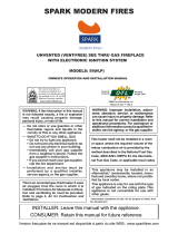
Version française de ce manuel est disponible à partir du site WEB : www.sparkfires.com
French version of this Owners Manual is available at www.
sparkfires
.com
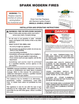
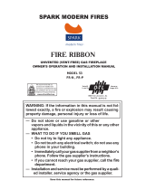
WARNING
flammable vapors and liquids in the
Do not store or use gasoline or other
vicinity of this or any other appliance.
WARNING
Read the installation, operating and maintenance
instructions thoroughly before installing or servicing
this equipment.
Improper installation, adjustment, alteration, service,
or maintenance can cause injury or property damage.
DANGER
CARBON MONOXIDE
HAZARD
This appliance can produce
carbon
monoxide
which
has no odor.
Using it in an
enclosed space can kill you.
Never
use
this
appliance
in
an
enclosed space
as a
camper, tent,
car
or
home
.
DANGER
If you smell gas:
1. Shut off gas to appliance.
2. Extinguish any open flame.
3. If odor continues, keep away from the
appliance and immediately call your
gas supplier or fire department.
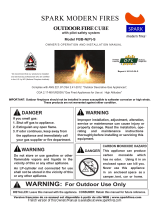
WARNING: For Outdoor Use Only
INSTALLER: Leave this manual with the appliance. CONSUMER: Retain this manual for future reference.
IMPORTANT: Outdoor fireplaces should not be installed in areas susceptible to saltwater corrosion or high winds.
These products are not warranted against either condition.
C
S
A 2.17-20
17
"Gas
-
Fired Appliances for Use at High Altitudes"
ANS Z21.97.CSA 2.41-201
7
"Outdoor Decorative Gas Appliances",
Complies with
A
propane
cylinder not connected for
use
shall not be stored in the vicinity
of this
or any other appliance.
Report # 0321GF007S
OUTDOOR FIRE TABLE

2
SAFETY
INFORMATION
WARNINGS
Natural Gas: Natural gas is odor-
less. An odor making agent is
added to the gas. The odor helps
you detect a gas leak. However,
the odor added to the gas can fade.
Gas may be present even though
no odor exists.
Make certain you read and under-
stand all warnings. Keep this
manual for reference. It is your
guide to safe and proper operation
of this appliance.
1. This appliance, as supplied, is
only for use with the type of
gas indicated on the rating
plate.
3. Keep the appliance area clear
and free from combustible
materials, gasoline and other
flammable vapors and liquids.
4. Do not burn solid fuel in the
fireplace after installing the
appliance. Do not use this
appliance to cook food or
burn paper or other objects.
5.
Children and adults should be
alerted to the hazards of
materials
carefully supervised when
they are in the area of the
appliance.
8. The appliance, when installed,
must be electrically grounded
in accordance with local codes
or, in the absence of local
codes, with the National Elec-
ely
call a qualif
any part of the
under water.
10. Inspect the burner before each
LOCAL CODES
. Follow local codes.
* American National Standards
Institute, Inc., 1430
Broadway, New York,
NY 10018
* National Fire Protection
Association, Inc.,
Batterymarch Park, Quincy,
MA 02269.
WARNING:
Any change
to this appliance or its
controls can be dangerous.
IMPORTANT:
The appliance
should be inspected before
use and at least annually by
a quilified service person.
More frequent cleaning may
be required as necessary. It
is imperative that the control
compartment, burners and
circulating air passageways
of the appliance be kept clean.
DANGER: Carbon mo-
noxide poisoning may lead
to death!
HIGH ALTITUDE
INSTALLATIONS:
7. Young children should be
should not be hung
from the appliance, or placed
on or near the app
liance.
6.
Clothing
or other flammable
high
surface temperatures and
should stay away to avoid
burns or clothing
ignition.
trical Code, ANSI/NFPA 70
or the Canadian Electrical
Code, CSA C22.1, if
applicable
.
The burner must be replaced
prior to the appliance being put
into operation if it is evident that
the burner is damaged.
Please
refer to "Illustrated parts List"
for the replacement burner part
number.
The appliance is rated for
installations up to 4500’ (1372 m)
above sea level. Above 4500’ the
appliance must be de- rated at the
factory for the appropriate altitude.
the
appliance. Only a qualified
service person should install,
service, or repair appliance.
11. Turn the appliance off and let
cool before servicing, install-
ling, or repairing. Any guard
or other protective device
removed for servicing the
appliance must be replaced
prior to operating
ied
service techn ician to inspect
the room appliance and to
replace
control
system and any gas control
which has been
9.
Do not use appliance if any
part has been under water.
Imm ediat
use of LBS-OD.
Carbon Monoxide Poisoning:
Early signs of carbon monoxide
poisoning resemble the flu, with
headaches, dizziness, or nausea. If
you have these signs, the
LBS-
OD
may not be working properly.
Get fresh air at once! Have the
LBSOD serviced.
Some people are
more affected by carbon
monoxide than others. These
include pregnant women, people
with heart or lung disease or
anemia, those under the influence
of alcohol, and those at high
altitudes.
2. When an appliance is for con-
nection to a fixed piping system,
the installation must conform
with local codes, or in the ab-
sence of local codes with the
National Fuel Gas Code, ANSI
Z223.1/NFPA 54, or
Interna-
tional Fuel Gas Code, Natural
Gas and Propane Installation
Code, CSA B149.1, or Pro-
pane Storage and Handling
Code, B149.2, as applicable.
Install and use
LBSOD with
care
.
In
the absence of local codes,
use the latest edition of The
National Fuel Gas Code ANSI
Z223.1/NFPA54 available from:

INSTALLATION
3
1)
When selecting a location for your fi replace, ensure that the clearances are met.
2)
This appliance must be installed in an open-air situation with natural ventilation, without
stagnant areas, where gas leakage and products of combustion are rapidly dispersed by wind
and natural convection.
3)
Certain materials or items, when placed under or near the appliance, will be subjected to radiant
heat and could become damaged.
4)
Typically an outdoor space is not enclosed but, any enclosure in which the appliance is used
shall comply with one of the following:
An enclosure with walls on all sides, but at least one permanent opening at ground level and
no overhead cover.
Within a partial enclosure that includes an overhead cover and more than two walls, the following
shall apply:
30% or more in total of the remaining wall
area is open and unrestricted.
Open side at least 25% of total wall area
LOCATING YOUR
OUTDOOR
GAS FIREPLACE
Within a partial enclosure that includes an overhead cover and no more that two walls.
• At least 25% of the total wall area is completely open, and
• At least 30% of the remaining wall area is open and unrestricted
IMPORTANT: Minimum ambient air temperature for the fireplace operation is 0°C (32°F)

2. Connect the Burner Assembly
to gas supply using supplied
flex connector and shutoff
valve.
3. Evenly fill the media
compartment with burner
media (broken tempered
glass) fully covering the
burner as shown on a picture.
If you are NOT planning to
add optional topping media,
then fill the media
compartment in full and
proceed to the step 5.
NOTE: If you are planning to
add some topping media
(optional colored glass or
lava rock), leave appro-
ximately ¾” not filled on top
of burner media and proceed
to the next step.
4. Place and evenly distribute
topping media (optional
colored glass or lava rock) on
top of burner media as shown
on a picture.
Make sure that pilot opening
is not blocked with excess of
media.
5. Carefully leak test all
connections following the
procedure on page 5.
1. Remove Burner Assembly,
Front Cover and Burner
Media from packaging (see
Parts List, page
14).
6. Having free access to the
valve and manifold
compartment of the Burner
Assembly turn ON the
appliance following the
procedure on page
8.
Make sure the flame is even
along the burner and
appliance is fully operational
and safe for use. Turn OFF
the appliance and let it cool
before proceeding to the next
step.
the parts in accordance with
these diagrams or failure to
use only parts specially
approved with this appliance
may result in property
the metal data plates
Burner System.
important information.
circulating air passageways
clean.
4
PRODUCT ASSEMBLY
INSTALLATION
CAUTION: Do not remove
WARNING: Failure to position
These plates contain
attached to the Linear
NOTICE: Installation and
repair should be done by a
qualified service person. The
appliance should be
inspected before use and at
least annually by a qualified
service person. More fre-
quent cleaning may be
required as necessary. It is
imperative that control
compartment, burner and
of the appliance be kept
WARNING:
Never light th
e
appliance
without
having the clear glass media
completely
covering
the burner
!
damage or personal injury.
- Top……… 60” (153 cm)
- Short Side of the Unit
to Wall ……. . 9” (23 cm)
- Long Side of the Unit
to Wall …… 16” (41 cm)
No Thermal Floor Protection Required
Fuel pressure specification:
Inlet
Nat. Gas
(NG)
Min:
4.5”
w.c.
Max:
10.5" w.c.
Manifold (NG)
3.5” w.c.
Inlet
Propane
Min:
11.0”
w.c.
Max:
13.0" w.c.
Manifold
10.0” w.c.
7. Cover manifold and valve
compartment of the Burner
Assembly with Front Cover.
Install the Rear Tray on oppo-
site side from the burner.
8. Fill the trays with topping
media to desired level.
CLEARANCES TO
COMBUSTIBLE MATERIALS
FROM BURNER:

5
NOTE:
Cover
(see Illustrated Parts List,
page 1
5
)
must be
in place when appliance is
not in use.
Firetable Dimensions
Firetable
can be installed on any
non-combustible materials.
FT36 - N (P)
FT48 - N (P)
FT60 - N (P)
FT72 - N (P)
FT84 - N (P)
FT96 - N (P)
FT108 - N (P)

FIREPLACE INSTALLATION
6
INSTALLATION
Continued
WARNING: Never connect
natural gas fireplace to private
(non-utility) gas wells. This
gas is commonly known as
wellhead gas.
Installation Items Needed
Before installing fireplace, make sure you have
the items listed below.
(if allowed by local codes) (not provided)
as shown in Figure 5. Pointing the vent down
protects it from freezing rain or sleet.
* Purchase the optional CSA design-certified
equipment shutoff valve from your dealer.
** Minimum inlet pressure for purpose of input
adjustment.
Sediment Trap
CSA Design-Certified
Equipment Shutoff Valve
With 1/8" NPT Tap*
3" Minimum
Cap Pipe Tee
Nipple Joint
C
A
U
T
I
O
N
: U
se o
n
l
y
n
ew,
black iron
or
steel
pipe. Inter-
nally-tinned
copper
tubing
may
be used
in
certain
areas.
Check
your
local
codes. Use
pipe
of
1/2"
diameter
or
greater
to allow
proper
gas
volume
to fireplace.
If
pipe is
too
small,
undue
loss
of volume will occur
.
In
s
t
a
l
l
a
t
i
o
n
m
u
s
t
i
n
c
l
u
d
e
a
n
e
q
u
i
p
m
e
n
t
sh
u
t
o
f
f
valve,
union and
plugged
1/8"
NPT
tap.
Locate
NP
T
ta
p
with
in
r
e
a
c
h
f
o
r
t
e
s
t
g
a
u
g
e
h
o
o
k
u
p
.
NPT
tap
must
be
upstream
from
fireplace
.
IMPO
R
T
AN
T
:
Install
equipment
shutof
f
valv
e
in
an
accessible
location.
The
equipment
shuto
f
f
valve
is
for
turning
on
or
shutting
of
f
the
gas
to
the appliance.
Check
your
building
code
s
for
any
special
r
e
-
quirements
for
locating
equipment
shuto
f
f
valve
to fireplaces
.
A
p
p
l
y
p
i
p
e
j
o
i
n
t
s
e
a
l
a
n
t
l
i
g
h
t
l
y
t
o
m
a
l
e
N
PT
th
r
e
a
d
s
. T
h
is
w
ill
p
r
e
v
e
n
t
e
x
c
e
s
s
s
e
a
la
n
t
f
r
o
m
g
o
i
n
g
i
n
t
o
p
i
p
e
.
Ex
c
e
s
s
s
e
a
l
a
n
t
i
n
p
i
p
e
c
o
u
l
d
r
e
s
u
l
t
in
clogged
fireplace
valves.
Never
use
sealant
on
flare threads.
External
Regulator
V
ent
Pointing
Down
SHUTOFF VALVE
A CSA design-certified equipment shutoff valve
with
1/8" NPT tap is an acceptable alternative to
test gauge connection. Purchase the optional CSA
design-certified equipment shutoff valve from your
dealer.
F
i
g
u
r
e
3
-
E
x
te
r
n
a
l
R
e
g
u
l
a
to
r
W
i
t
h
V
e
n
t
P
o
i
n
t
i
n
g
D
o
w
n
Figure
4
- Gas Connection
• external regulator for propane unit only
(supplied by installer)
• piping (check local codes)
• sealant (resistant to propane gas)
• equipment shutoff valve *
• test gauge connection *
• sediment trap (optional)
• tee joint
• pipe wrench
• approved flexible gas line with gas connector
For propane units, the installer must supply an
external regulator. The external regulator will
reduce incoming gas pressure. You must reduce
incoming gas pressure to between 11 and 14 inches
of water. If you do not reduce incoming gas pres-
sure, heater regulator damage could occur. Install
external regulator with the vent pointing down
Natural Gas
From Gas Meter
(5" W.C.** to 10.5"
W.C. Pressure)
Propane
From External
Regulator
(11" W.C.** to 14"
W.C. Pressure)
Propane
Supply
Tank

7
NOTICE: Most building codes
do not permit concealed gas
connections. A flexible gas line
is provided to allow
shutoff
valve should be accessible.
INSTALLATION
Continued
Flexible Gas Line
from Fireplace
Gas Regulator
To Fireplace
Gas Regulator
Equipment
Shutoff Valve
Provided by
Installer
Natural Gas
To Gas Meter
sediment trap where it is within reach for clean-
ing. Install in piping system between fuel supply
and fireplace. Locate sediment trap where trapped
matter is not likely to freeze. A sediment trap traps
moisture and contaminants. This keeps them from
going into fireplace gas controls. If sediment trap
is not installed or is installed wrong, fireplace may
not run properly.
CONNECTING FIREPLACE TO GAS
SUPPLY
1. Remove access panel.
2. Route gas line (provided by installer) from
equipment shutoff valve to fireplace. Route
flexible gas supply line through one of the
access holes.
3. Attach the flexible gas line to gas supply as
1. Check gas type. The gas supply must be the same as
stated on the appliance’s rating decal. If the gas supply
is different from the replace, STOP! Do not install the
appliance. Contact your dealer immediately.
2. To ease installation, a 30" (mm) ex line with
manual
shut-off valve has been provided with on this appliance.
Install and attach
1
/
2
" gas line onto shut-off valve.
Outlet Pressure Tap
Pilot Adjustment
Inlet Pressure Tap
4.
Do not use open flame to check for gas leaks.
WARNING
3. After completing gas line connection, purge air from
gas line and test all gas joints from the gas meter to the
replace for leaks. Use a solution of 50/50 water and
soap or a gas sniffer.
T
o check gas pressures at the valve, turn captured
screw counter clockwise 2 or 3 turns and then place
tubing to pressure gauge over test point.
Turn unit to high. After taking pressure reading,
be sure and turn captured screw clockwise
firmly to reaseal. Do not overtorque. Check
test points for gas leaks!
Figure 5 - Attaching Flexible Gas Lines
Together
per Figure
5
. Check tightness of flexible gas
line attached to gas regulator of fireplace and
check all gas connections for leaks ( see
accessibility
from the fireplace (see Figure
5). The
flexible gas supply line con-
nection to the equipment
Checking Gas Connections, page
21
).
We recommend that you install a sediment trap in
supply line as shown in Figure 4, page 1
9
.
Locate
CHECKING GAS PRESSURE
WARNING: Use pipe joint
sealant that is resistant to liquid
petroleum (
propane
) gas.
Propane
To External
Regulator

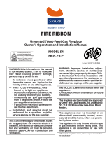
BURNER DIMENSIONS
OVERALL
ORIF. SIZE
LENGTH
WIDTH (W)
INPUT RATE (B
tu
/
hr
)
8
36
"
32" 6
1,000 54
,000
3 (1)
44 4
3
60
"
56" 102
,000 90
,000
116,000
110,000
5
(
2
)
4
3
4
6
1
29
,000
128,000
MODEL
# ORIF.
N.G.
Propane
N.G. (Prop.)
BURNER TUBE
N.G.
Prop.
MEDIA BURNER TRAY
PILOT
BURNER TUBE
10"
3"
4.25"
6"
7"
1.5"
OVERAL WIDTH (W)
*
TOP COVER DIMENSIONS
*
TOP COVER
WELD-ON HANDLE
TOP COVER WIDTH (W+0.65")
4"
1"
2
.5"
1
7
.5"
4"
1
6"
FT36 - N (P)
24" 20"
41,000
33,500
2 (1)
44 49
FT48 - N (P)
FT60 - N (P)
48" 44"
82,000
72,000
4 (1)
4
3
38
FT72 - N (P)
FT
84 - N (P)
72" 68"
6 (2)
43
41
FT
96 - N (P)
84" 80"
7 (2)
43 38
FT
108 - N (P)
96" 92"
142,000 146
,500 8
(2) 43 35
LINEAR BURNER SYSTEM OUTDOOR SPECIFICATIONS

32 L100001
A.This appliance is equipped with an ignition device which automatically lights the pilot. Do not try to light
the pilot by hand.
B. BEFORE OPERATING smell all around the appliance area for gas. Be sure to smell next to the oor because
some gas is heavier than air and will settle on the oor.
WHAT TO DO IF YOU SMELL GAS:
• Do not try to light any appliance.
• Do not touch any electric switch; do not use any phone in your building.
• Immediately call your gas supplier from a neighbor's phone.
Follow the gas supplier's instructions.
• If you cannot reach your gas supplier, call the fire department.
D. Do not use this appliance if any part of it has been under water. Immediately call a qualied service technician
to inspect the appliance and to replace any part of the control system and any gas control that has been under
water.
LIGHTING INSTRUCTION
FOR YOUR SAFETY READ BEFORE OPERATING
LIGHTING FOR THE FIRST TIME
INITIAL LIGHTING
Purge air from the supply line as follows:
• Open main shutoff valve.
• Unscrew main pressure test point.
• Leave inlet test screw open until gas comes in.
• When gas is owing, tighten inlet screw immediately.
LEAK TESTING
1. Follow the pipe from the gas supply line connection to the gas valve. Check connection for leaks with soap
and water mixture.
2. Next check for gas leaks at the burner with soap and water mixture.
3. Check the pilot for gas leaks with soap and water mixture.
If you do not follow these instruction exactly,
a fire or explosion may result causing property
damage, personal injury or loss of life.
WARNING
Never use an open flame to check for gas leak.
DANGER
9
as it may result in a fire or explosion. Call a qualified service technician if you have any safety concerns.
C. Main gas valve in this appliance is not serviceable and does not have any control knobs or switches to operate.
Do not remove heat shields covering the valve and electronic devices; do not try to repair or modify the valve

L100001 35
Continued
APPROVED LEAK TESTING METHOD
You may check for gas leaks with the following methods only:
• Soap and water solution
• An approved leak testing spray
• Electronic sniffer
NOTE: Remove any excessive pipe compound from
the connections. Excessive pipe compound can set
off electronic sniffers.
"INSTALLATION AND OPERATING INSTRUCTIONS FOR SKYTECH MODEL: 1001 T/LCD-A"".
OPERATING INSTRUCTIONS
Check for gas leaks in each of the following locations:
• Pipe from the gas supply line connection to the gas valve
• Burner connections, pilot • Field made joints / gas shutoff valve
• All joints on valve and control body • Factory made joints, each joint and connection
WA
If using a soap and water solution to test
for leaks, DO NOT spray solution onto
electronic parts.
WARNING
Never use an open flame to check for gas leak.
DANGER
1. STOP! Read the safety information on previous page.
2. Turn off all electric power to the appliance.
3. Do not attempt to light the pilot by hand.
If you don't smell gas, go to the next step.
WARNING
7. Turn the gas control manual valve to the ON position.
8. Plug supplied 7V DC adapter into 110V power outlet.
LIGHTING FOR THE FIRST TIME
4. Remove Front Tray from the appliance (see Illustrated Parts List, page 14).
5. Turn the gas control manual valve to the full OFF position.
6. Wait five (5) minutes to clear out any gas. Then smell for gas, including near the floor.
If you smell gas, STOP! Follow "B" in the safety information (see page 7).
9. Connect the wire to the DC input plug at the unit.
11. Locate Remote Receiver inside of the unit
(see Illustrated Parts List, page 13).
Make sure that the slider switch
13. Read and follow instructions in how to set up and to use remote control described in supplied
14. If the appliance will not operate, follow the instructions "To Turn Off Gas To Appliance" and call
your service technician or gas supplier.
of the Receiver is in "REMOTE"
(middle) position.
10. Lift and remove Heat Shield covering electronic components inside of the unit
(see Illustrated Parts List, page 13).
12. Replace Heat Shield and then replace Front Tray.
10

34 L100001
T
TO TURN OFF GAS TO APPLIANCE
Unplug 7V DC adapter from the power outlet.
3. Turn the gas control manual valve to the full OFF position.
1. Turn off all electric power to the appliance if service is to be
performed.
2. If necessary, remove Front Tray from the appliance to access
manual shutoff valve on gas line.
4. If necessary, replace Front Tray.
11
ELECTRICAL WIRING
WARNING
Label all wires before disconnecting when
servicing controls. Wiring errors can cause
improper and dangerous operation.
CAUTION
Electrical connections should only be performed by a qualified, licensed electrician.
Main power must be off when connecting to main electrical power supply or performing
service. All wiring shall be in compliance with all local, city, and state codes. The
appliance, when installed, must be electrically grounded in accordance with local
codes, or in the absence of local codes, with the National Electrical Code ANSI/ NFPA
70 (latest edition) and Canadian Electrical Code, CSA C22.1.
adapter which is required to operate Remote Control. However, during power outage situation, its electronic
system (DFC board) can be temporarily powered with 6V DC battery pack (4 AA batteries).
This fireplace requires 110V
AC electrical supply for normal operation in order to power up
7V DC
Continued
WARNING
within the appliance.
Do not operate the appliance without the burner being completely filled with glass media.
Lighting the burner without the glass media will cause unsafe temperatures

CLEANING AND MAINTENANCE
BURNER, PILOT AND CONTROL COMPARTMENT
PILOT FLAME
BURNER
Turn off gas before servicing fireplace. It
is recommended that a qualified service
technician perform these check-ups at the
beginning of each heating season.
WARNING
1
Pilot Flame
Keep the control compartment clean by vacuuming or brushing at
least twice a year. Make sure the burner porting, pilot air opening
and burner air opening are free of obstructions at all times.
normal operation.
12
The fames from the pilot should be visually checked as soon as the unit is installed
and periodically during normal operation. The pilot flame must always be present
when the fireplace is in operation or connected to the gas line with main shutoff
valve open and the IPS activated (powered). The pilot flame has two distinct
flames, one engulfing the flame sensor and the other reaching to the main burner.
Keep the
appliance and its burner clean by vacuuming or brushing at
least twice a year. Make sure the burner porting and burnerair
openings are free of obstructions at all times.
Inspect area around the burner. Remove any lint or foreign
material with a brush or vacuum.
The burner must be replaced prior to the appliance being put
into operation if it
is evident that the burner is damaged. Please
refer to "Illustrated Parts List" for the replacement part number
specified by the manufacturer.

TROUBLESHOOTING
13
WARNING: Turn off the unit
and let cool before servicing. Only
a qualified service person should
service and repair this appliance.
OBSERVED PROBLEM POSSIBLE CAUSEREMEDY
OBSERVED PROBLEM
1. Poor fuel quality
2.Excessive flame impingement or block-
age
3.Improper fuel/air mixture
1. Passage of air/gas across irregular sur-
faces
2. Excessive gas pressure on natural gas
units
1. Incorrect gas supply or pressure
2. Blocked burner orifice or burner mani-
fold ports
3. Improper burner orifice size
1. Battery is not installed. Battery power
is low.
Unit is smoking / sooting excessively
(
Note:
It is natural and unavoidable for
appliance sets to produce moderate
levels of carbon (soot) where flames
Burner is excessively noisy
(
Note:
The movement and combustion of
gas will create low, unavoidable levels of
noise.)
Burner flame is too low or too high
Remote does not function
1.Contact local natural gas company
2.Separate the stones/media to allow
more flame passage
3.Remove any foreign items from the
flame pattern and/or check for proper
orifice sizing
1. Relieve any tight bends or kinks in gas
supply line
2.Check/reset gas regulator pressure
1. Check for proper gas supply pressure
2. Free burner orifice and manifold ports
of any burrs, paint, or other blockage
3. Verify proper burner orifice sizing (see
1.Replace batteries in receiver and
remote control
Note:
All troubleshooting items are listed in
order of operation.
contact the media. This is especially true
page 7)

Continued
13
1. Gas leak. See Warning statement at
top of page
position
Gas odor during combustion 1. Locate and correct all leaks (see Check-
ing Gas Connections, page 5)
14
OBSERVED PROBLEM
When ignitor button is pressed, there is
spark at pilot but no ignition
Burner does not light after pilot is lit
Delayed ignition burner
Unit produces unwanted odors
Gas odor even when Remote Control is
REMEDY
1.Turn on gas supply or open manual
2.Purge air from the supply line
1" blue flame
4.Clean pilot (see Cleaning and Mainte-
1.Clean burner orifice
3.Replace burner orifice
4.Reconnect leads
1.Adjust pilot flame for approximately
1" blue flame
POSSIBLE CAUSE
1.Gas supply turned off or manual shutoff
valve closed shutoff valve
2.Air in gas lines when installed
3.Pilot adjustment screw closed
4.Pilot is clogged
5.Ignitor electrode broken
1.Burner orifice clogged
2.Inlet gas pressure is too low
3.Burner orifice diameter is too small
4.Flame sensor leads disconnected
1.Pilot flame needs adjusting
1. Gas leak. See Warning statement above.
1.Gas leak. See Warning statement above.
IMPORTANT:
Operating unit where impurities in air exist may create odors.
Cleaning supplies, paint, paint remover, cigarette smoke, cements and glues, new
carpet or textiles, etc., create fumes. These fumes may mix with combustion air
and create odors. These odors will disappear over time.
WARNING: If you smell gas
• Shut off gas supply.
• Do not try to light any appliance.
• Do not touch any electrical switch; do not use any phone in
your building.
• Immediately call your gas supplier from a neighbor’s phone.
Follow the gas supplier’s instructions.
• If you cannot reach your gas supplier, call the fire department.
(see page
8)
3. Adjust pilot flame for approximately
nance, page 1
1) or replace pilot assembly.
5. Low gas pressure
1. Locate and correct all leaks
.
2. Main gas valve defective 2. Replace gas valve
1. L o c a t e a n d c o r r e c t a l l l e a k s
in OFF position
2. Contact your gas supplier

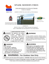
ILLUSTRATED PARTS LIST
O W N E R ’ S O P E R A T I O N A N D I N S T A L L A T I O N M A N U A L
ILLUSTRATED PARTS LISTILLUSTRATED PARTS LIST
FOR PART DESCRIPTION SEE NEXT PAGE
16
ILLUSTRATED PARTS LIST
15
16
18
15
14
1
8
5
2
3
4
6
7
9
10
11
12
13
17
19

PARTS LIST
Key
#
Part Description
Q-
ty
Valve Bracket
(NOT SHOWN)
Manifold complete
with Tubing Assembly
Continued on Next Page
This list contains replaceable parts used in your
(W120202)
(W120204)
(R100029)
W120203
(W120203)
W120205
(W120205)
R100026
(R100027)
R100026
(R100027)
R100028
(R100029)
R100028
(R100029)
H100141
H100141
D400260
D400260
D400261
D400261
All replacement parts should be ordered from your
retai
ler or from
Spark Modern Fires
at
1-
866-938-3846 or on-line at www.sparkfires.com
C100010
D300098
4
Burner Flex Connector
C1000
10
(W120206)
(W120207)
(W120208)
(R100027)
(R100027)
(R100027)
(R100027)
(R100027)
3
Pilot Assembly
R10002
8
R10002
8
R10002
8 R100028
R10002
8 1
(R100029)
(R100029)
(R100029) (R100029)
D3
00098
D300098 D300098 D300098 1
5 DFC
Wire Assembly
H100141
H100141
H100141
H100141 H100141
1
6
D400260
D400260
D400260
D400260 D400260
1
7
Valve
Heat
Shield
D400261
D400261
D400261
D400261 D400261
1
8
MISC. MISC.
W130204
W130205
W130206 W130207 W130208
1
(MISC.) (MISC.) (MISC.) (MISC.) (MISC.) (MISC.) (MISC.)
1
Burner Assembly
W110
2
02
W110
2
04
W110
2
06 W110207
W110
2
08
1
NG (Propane)
2
Main Gas Valve
R10002
6
R10002
6
R10002
6
R100026
R10002
6 1
NG (Propane)
NG (Propane)
NG (Propane)
Part Number
a
ccording to the Fire Table
Natuaral Gas model (and Propane)
Fire Table outdoor appliance
FT36 FT48 FT60 FT72 FT84 FT96 FT108

PARTS LIST
(CONTINUED)
Key
#
Part Description
Q-
ty
R100043
(D400290)
R100044
(R200062)
(D400290)
D400267
D400267
(D400290)
D4002
65
D400265
H1
00142
H1
00142
H100140
H100140
Remote Control
H100139
H100139
R100043
R100043 R100043
R100043
10 Front Tray D400234 D400254 D400253 D400209 D400217 D400224 D400210 1
11 Unit Cover D400272 D400273 D400274 D400275 D400276 D200277 D400278 1
12
Pilot Shield
D400267
D400267
D400267
D400267 D400267
1
(D400290)
(D400290) (D400290)
(D400290)
13
Control Heat Shield
D400265
D400265
D400265 D400265 D400265
1
14
DFC Board
H100142
H100142
H100142
H100142 H100142
1
15
Remote Receiver
RCB-R RCB-R RCB-R RCB-R
RCB-R RCB-R RCB-R 1
17
6 Volt Battery Pack
H100139
H100139
H100139 H100139 H100139
1
18
7V 10mA DC adapter
H100140
H100140
H100140
H100140 H100140
1
-
Topping Media MISC. MISC. MISC. MISC. MISC. MISC. MISC. Pkg
- Burner Glass Media G100030 G100030 G100030
G100030 G100030 G100030 G100030 Pkg
/standard/
1
6 RCB RCB RCB RCB RCB RCB RCB 1
SEE PAGE # 7
(R200064)
(R100066) (R100063)
(R200061)
(R200063)
(R200067)
Part Number
a
ccording to the LBS
-
OD Natuaral Gas model (and Propane)
9
Orifice for "N" models
R100044
(Air
m
ixer for
"
P
"
model
s
)
19
Enclosure Cover W100279 W100280 W100281 W100282 W100283
W100284 W100285
1
FT36 FT48 FT60 FT72 FT84 FT96 FT108

ILLUSTRATED PARTS LIST
SEE NEXT PAGE
FOR PART DESCRIPTION
ILLUSTRATED PARTS LIST
SEE NEXT PAGE
FOR PART DESCRIPTION
2
ILLUSTRATED PARTS LIST
SEE NEXT PAGE
FOR PART DESCRIPTION
ILLUSTRATED PARTS LIST
SEE NEXT PAGE
FOR PART DESCRIPTION
2
17
Pilot Assembly
6 Volt Battery Backup ( uses 4 pcs AA Batteries)

Date Purchased:
Purchaser/Dealer:
Installer:
Fireplace S/N on product ID tag:
Date Installed:
FUEL:
◯
◯
Natural Gas
◯
◯
L.P. Propane
Inlet Pressure Measured After Installation:
In. W.C.
Manifold Pressure Measured After Installation:
High Fire:
In. W.C. Low Fire: In. W.C.
CONFIGURATION:
ALTITUDE: Feet Above Sea Level
Was Fireplace Derated?
◯
Yes
◯
No
If Yes To What Orifice Size?
Unusual Structure Near Appliance?
◯
◯
Inside Corner
◯
◯
Trees/Shrubs
◯
◯
Other
Termination:
(Please Describe)
Prevalent Wind Conditions?
Other Installation Notes:
The installer should complete the form below that describes the details of the installation. Having this
written record of installation information available will greatly expedite trouble-shooting should any problem
arise with your fireplace. The installer should keep a duplicate of this form for their records. Accurate com-
pletion of this form is required for warranty coverage and for any technical support by Spark Modern Fires.
SMF32011
INSTALLATION RECORD

LIMITED LIFETIME WARRANTY
The following components are warranted for life to the original owner, subject to proof of
purchase: Firebox, Combustion Chamber, and Steel Burner.
BASIC WARRANTY
Spark Modern Fires warrants the components and materials in your gas appliance to be
free from manufacturing and material defects for a period of two years from date of instal-
lation. After installation, if any of the components manufactured by Spark Modern Fires in
the appliance are found to be defective in materials or workmanship, Spark Modern Fires
will, at its option, replace or repair the defective components at no charge to the original
owner. Spark Modern Fires will also pay for reasonable labor cost incurred in replacing or
repairing such components for a period of two years from date of installation. Any products
presented for warranty repair must be accompanied by a dated proof of purchase.
This Limited Lifetime Warranty will be void if the appliance is not installed by a qualified
installer in accordance with installation instructions. The Limited Lifetime Warranty will also
be void if the appliance is not operated and maintained according to the operating in-
structions supplied with the appliance, and does not extend to (1) firebox/burner assembly
damaged by accident, neglect, misuse, abuse, alterations, negligence of others, including
the installation thereof by unqualified installers, (2) the costs of removal, re-installation or
transportation of defective parts on the appliance, or (3) identical or consequential dam-
age. All service work must be performed by an authorized service representative.
This warranty is expressly in lieu of other warranties, express or implied, including the
warranty of merchantability of fitness for purpose and of all other obligations or liabilities.
Spark Modern Fires does not assume for it any other obligations or liabilities in connection
with sale or use of the appliance. It states that do not allow limitations on how long an
implied warranty lasts, or do not allow exclusion of indirect damage, those limitations of
exclusions may not apply to you. You may also have additional right not covered in the
Limited Lifetime Warranty. Spark Modern Fires reserves the right to investigate any and all
the claims against this Warranty and decide upon method of settlement.
For information about this warranty contact:
SPARK MODERN FIRES
99B Greenwood Ave Bethel, CT 06801 USA P. 203.791.2725 F. 203.798.8661
WWW.SPARKFIRES.COM
WARRANTY INFORMATION
Model:
Serial No.:
Date Purchased: Date Installed:
Always specify model and serial numbers when communicating with the factory.
Rev. No: 11/2020
/