DeWalt D26677K TYPE 1 Owner's manual
- Category
- Power tools
- Type
- Owner's manual

0
,I 8
@
0 m
Q.
I
.__
DEWALT Industrial Tool Co., 701 Joppa Road, Baltimore, MD 21286
(APR10) Part No. N070577 D26676, D26677 Copyright © 2010 DEWALT
The following are trademarks for one or more DEWALT power tools: the yellow and black color
scheme; the "D" shaped air intake grill; the array of pyramids on the handgrip; the kit box configu-
ration; and the array of lozenge-shaped humps on the surface of the tool.
Definitions: Safety Guidelines
The definitions below describe the level of severity for each signal word. Please read
the manual and pay attention to these symbols.
ADANGER: Indicates an imminently hazardous situation which, if not avoided, will
result in death or serious injury.
,&WARNING: Indicates a potentially hazardous situation which, if not avoided, could
result in death or serious injury.
_,CAUTION: Indicates a potentially hazardous situation which, if not avoided, may
result in minor or moderate injury.
NOTICE: Indicates a practice not related to personal injury which, if not avoided,
may result in property damage. )
IF YOU HAVE ANY QUESTIONS OR COMMENTS ABOUT THIS OR ANY DEWALT TOOL,
CALL US TOLL FREE AT: 1-800-4-DEWALT (1-800-433-9258).
_ WARNING: To reduce the risk of injury, read the instruction manual.
General Power Tool Safety Warnings
_ ARNING! Read all safety warnings and instructions Failure to follow the warnings
and instructions may result in electric shock, fire and/or serious injury,
SAVE ALL WARNINGS AND INSTRUCTIONS
FOR FUTURE REFERENCE
The term "power tool" in the warnings refers to your mains-operated (corded) power tool or
battery-operated (cordless) power tooL
1) WORK AREA SAFETY
a) Keep work area clean and well lit. Cluttered or dark areas invite accidents.
b) Do not operate power tools in explosive atmospheres, such as in the presence of
flammable liquids, gases or dust. Power tools create sparks which may ignite the dust
or fumes.
c) Keep children and bystanders away while operating a power tooL Distractions can
cause you to lose control
2) ELECTRICAL SAFETY
a) Power tool plugs must match the outlet. Never modify the plug in any way. Do not
use any adapter plugs with earthed (grounded) power tools. Unmodified plugs and
matching outlets will reduce risk of electric shock.
b) Avoid body contact with earthed or grounded surfaces such as pipes, radiators,
ranges and refrigerators. There is an increased risk of electric shock if your body is
earthed or grounded.
c) Do not expose power tools to rain or wet conditions. Water entering a power tool will
increase the risk of electric shock.
d) Do not abuse the cord. Never use the cord for carrying, pulling or unplugging the
power tooL Keep cord away from heat, oil, sharp edges or moving parts. Damaged
or entangled cords increase the risk of electric shock.
e) When operating a power tool outdoors, use an extension cord suitable for outdoor
use. Use of a cord suitable for outdoor use reduces the risk of electric shock.
f) ff operating a power tool in a damp location is unavoidable, use a ground fault
circuit interrupter (GFCl) protected supply. Use of a GFCI reduces the risk of electric
shock.
3) PERSONAL SAFETY
a) Stay alert, watch what you are doing and use common sense when operating a
power tool. Do not use a power tool while you are tired or under the influence of
drugs, alcohol or medication. A moment of inattention while operating power tools may
result in serious personal injury.
b) Use personal protective equipment. Always wear eye protection. Protective equipment
such as dust mask, non-skid safety shoes, hard hat, or hearing protection used for
appropriate conditions will reduce personal injuries.
c) Prevent unintentional starting. Ensure the switch is in the off position before
connecting to power source and/or battery pack, picking up or carrying the tool
Carrying power tools with your finger on the switch or energising power tools that have
the switch on invites accidents.
d) Remove any adjusting key or wrench before turning the power tool on. A wrench or
a key left attached to a rotating part of the power tool may result in personal injury,
e) Do not overreach. Keep proper footing and balance at all times. This enables better
control of the power tool in unexpected situations.
f) Dress properly. Do not wear loose clothing or jewellery. Keep your hair, clothing and
gloves away from moving parts. Loose clothes, jewellery or long hair can be caught in
moving parts.
g) ff devices are provided for the connection of dust extraction and collection facilities,
ensure these are connected and properly used. Use of dust collection can reduce
dust-related hazards.
4) POWER TOOL USE AND CARE
a) Do not force the power tooL Use the correct power tool for your application. The
correct power tool will do the job better and safer at the rate for which it was designed.
b) Do not use the power tool if the switch does not turn it on and off. Any power tool
that cannot be controlled with the switch is dangerous and must be repaired.
c) Disconnect the plug from the power source and/or the battery pack from the power
tool before making any adjustments, changing accessories, or storing power tools.
Such preventive safety measures reduce the risk of starting the power tool accidentally.
d) Store idle power tools out of the reach of children and do not allow persons
unfamiliar with the power tool or these instructions to operate the power tool Power
tools are dangerous in the hands of untrained users.
e) Maintain power tools. Check for misalignment or binding of moving parts, breakage
of parts and any other condition that may affect the power tool's operation, ff
damaged, have the power tool repaired before use. Many accidents are caused by
poorly maintained power tools.
f) Keep cutting tools sharp and clean. Properly maintained cutting tools with sharp
cutting edges are less likely to bind and are easier to control.
g) Use the power tool, accessories and tool bits, etc. in accordance with these
instructions, taking into account the working conditions and the work to be
performed. Use of the power tool for operations different from those intended could
result in a hazardous situation.
5) SERVICE
a) Have your power tool serviced by a qualified repair person using only identical
replacement parts. This will ensure that the safety of the power tool is maintained.
Additional Safety Instructions for Planers
• Wait for the cutter to stop before setting the tool down. An exposed cutter may engage
the surface leading to possible loss of control and serious injury
• Use clamps or another practical way to secure and support the workpiece to a stable
platform. Holding the work by hand or against your body leaves it unstable and may lead to
loss of control
• Be sure the voltage agrees with specific data on the nameplate.
• Make certain that the switch is in the offposition before connecting plug to a power source.
• Be sure to switch OFF immediately if tool is jammed in work.
• Be sure tool is set for correct depth before turning switch to ON.
• Be sure to maintain tool with care. Follow instructions for lubricating and changing
accessories.
• Stay alert - never operate the unit when tired or under the influence of drugs, alcohol or
medication.
• Be sure to store tool in a clean dry place after disconnecting from power source.
• Do not use in dangerous environments. Do not use near flammable substances, in damp or
wet locations, or expose to rain.
• Be sure that the blades are mounted as described in the instruction manual and check that
aft screws are firmly tightened before connecting unit to power source.
• Keep air vents unobstructed for proper motor cooling.
• DO NOT lay tool down on shoe when the blades are exposed. This can chip the blades.
• Keep side discharge chute unobstructed at all times.
• Never reach under the tool for any reason unless it is turned off and UNPLUGGED. BLADES
ARE EXPOSED AND EXTREMELY SHARR
• Use this tool for working with wood and wood products only,
• Never operate without securely holding the front handle.
• Always operate planer with two hands.
• Planer blades are extremely sharp. Handle with great care.
• Clean out your tool often, especially after heavy use.
• Air vents often cover moving parts and should be avoided. Loose clothes, jewellery or
long hair can be caught in moving parts.
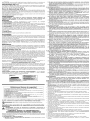
• An extension cord must have adequate wire size (AWG or American Wire Gauge) for
safety. The smaller the gauge number of the wire, the greater the capacity of the cable, that
is 16 gauge has more capacity than 18 gauge. An undersized cord will cause a drop in line
voltage resulting in loss of power and overheating. When using more than one extension to
make up the total length, be sure each individual extension contains at least the minimum
wire size. The following table shows the correct size to use depending on cord length and
nameplate ampere rating, ff in doubt, use the next heavier gauge. The smaller the gauge
number, the heavier the cord.
Ampere Rating
More
Than
0
6
10
12
Not More
Than
6
10
12
16
Minimum Gauge for Cord Sets
Volts Total Length of Cord in Feet (meters)
120V 25 (7.6) 50 (15.2) 100 (30.5) I 150 (45.7)
240V 50 (15.2) 100 (30.5) 200 (61.0) I 300 (91.4)
AWG
18
18
16
14
16
16
16
12
16 14
14 12
14 12
Not Recommended
WARNING: ALWAYS use safety glasses. Everyday eyeglasses are NOT safety glasses. Also
use face or dust mask if cutting operation is dusty, ALWAYS WEAR CERTIFIED SAFETY
EQUIPMENT:
• ANSI Z87.1 eye protection (CAN/CSA Z94.3),
• ANSI $12.6 ($3.19) hearing protection,
• NIOSH/OSHA/MSHA respiratory protection.
,&WARNING: Some dust created by power sanding, sawing, grinding, drilling, and other
construction activities contains chemicals known to cause cancer, birth defects or other
reproductive harm. Some examples of these chemicals are:
• lead from lead-based paints,
• crystalline silica from bricks and cement and other masonry products, and
• arsenic and chromium from chemically-treated lumber (CCA).
Your risk from these exposures varies, depending on how often you do this type of work.
To reduce your exposure to these chemicals: work in a well ventilated area, and work with
approved safety equipment, such as those dust masks that are specially designed to filter out
microscopic particles.
• Avoid prolonged contact with dust from power sanding, sawing, grinding, drilling, and
other construction activities. Wear protective clothing and wash exposed areas with
soap and water. Allowing dust to get into your mouth, eyes, or lay on the skin may promote
absorption of harmful chemicals.
_ WARNING: Use of this tool can generate and/or disburse dust, which may cause serious and
permanent respiratory or other injury. Always use NIOSH/OSHA approved respiratory
protection appropriate for the dust exposure. Direct particles away from face and body,
WARNING: Always wear proper personal hearing protection that conforms to ANSI
$12.6 ($3.19) during use. Under some conditions and duration of use, noise from this product
may contribute to hearing loss.
• The label on your tool may include the following symbols. The symbols and their definitions
are as follows:
V...................... volts
Hz .................... hertz
min .................. minutes
--- ............... direct current
(_) .................... Class I Construction
(grounded)
[] .................... Class II Construction
(double insulated)
.../min ............. per minute
IPM.................. impacts per minute
A...................... amperes
W..................... watts
"_ ................... alternating current
................... alternating or direct current
no .................... no load speed
.................... earthing terminal
•& .................... safety alert symbol
BPM ................ beats per minute
RPM ................ revolutions per minute
SAVE THESE INSTRUCTIONS

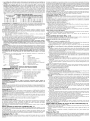
COMPONENTS (Fig. 1)
_, WARNING: Never modify the power tool or any part of it. Damage or personal injury could
result.
A. On/Off switch
B. Lock-on button
C. Main handle
D. Rear shoe
E. Drive belt cover
R Hole for rabbet fence
G. Front shoe
OPERATION
H. Rabbet fence tightening knob
I. Planing depth graduation
J. Planing depth adjustment knob/front handle
K. Chip discharge chute
L. Dust adapter
M. Rabbetting cover
WARNING: To reduce the risk of serious personal injury, turn tool off and disconnect
tool from power source before making any adjustments or removing/installing attachments
or accessories.
Motor
Be sure your power supply agrees with the nameplate marking. Voltage decrease of more than
10% will cause loss of power and overheating. DEWALT tools are factory tested; if this tool does
not operate, check power supply.
Switch (Fig. 1)
_ CAUTION: Check that the tool is not locked ON before connecting it to a power supply. If the
trigger switch is locked ON when the tool is connected to the power supply, it will start
immediately. Damage to your tool or personal injury may result.
_ CAUTION: Allow the tool to reach full speed before touching tool to the work surface. Lift the
tool from the work surface before turning the tool off.
To start the planer depress the on/off switch (A).
To turn the planer off, release the on/off switch.
LOCK-ON BUTTON
The tool can be locked on for continuous use. To lock the tool on, depress the trigger switch (A)
and push in the lock-on button (B). Hold the lock-on button in as you gently release the trigger
switch. The tool will continue to run.
To turn the tool off from a locked-on position, squeeze and release the trigger once.
Adjusting the Planing Depth (Fig. 1)
To adjust the depth of cut, turn the planing depth adjustment knob (J). Each click is equal to
0.1 mm of depth up to the maximum depth of cut of approximately 1/16" (1.6 mm).
It is recommended that test cuts be made in scrap wood after each re-adjustment to make sure
that the desired amount of wood is being removed by the planer. Several shallow passes (rather
than one deep one) will produce a smoother finish.
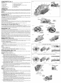
Planing (Fig. 1-4)
,6,CAUTION: Allow the tool to reach full speed before touching tool to the work surface. Lift the
tool from the work surface before turning the tool off.
Hold the planer in the correct position with one hand on the front handle (J) and the other hand
on the main handle (C) as shown in Figure 2. Place the front shoe (G) on the surface to be
planed, making certain that the cutting blades are not touching the surface. Push down firmly on
the front handle of the planer so that the front shoe is ABSOLUTELY FLAT on the work surface.
Squeeze the trigger switch and allow the motor to reach full speed before touching the planer
blades to the work surface.
Move the tool slowly into the work and maintain downward pressure to keep the planer flat. Be
particularly careful to keep the tool flat at the beginning and the end of the work surface.
Planing Tip: For a smoother appearance, fasten a piece of scrap wood to the end of the piece
you are planing. Don't stop planing until the cutting blades of the planer are past your workpiece
and into the scrap material.
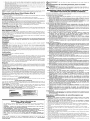
Rabbet Fence (Fig. 5, 6)
A WARNING: Allow the tool to reach full speed before touching tool to the work surface. Lift the
tool from the work surface before turning the tool off.
The rabbet fence (N) is used for optimum tool control on narrow workpieces and can be installed
on either side of your planer. The planer makes rabbet cuts up to 23/64" (9 mm).
TO INSTALL RABBET FENCE
1. Loosen the rabbet fence tightening knob (H).
2. Slide the crossbar on the rabbet fence (N) into the hole (F) on the side of the planer as shown
in Figure 5.
3. Set the width of cut by adjusting the edge guide across the width of the shoe.
4. Securely tighten rabbet fence tightening knob.
NOTE: The rabbet fence should be below the planer when installed correctly as shown in
Figure 6
TO MAKE A RABBET CUT
1. Turn the rabbet fence tightening knob (H) to adjust the desired width of cut.
2. Make several cuts until the desired depth is reached.
NOTE: It will be necessary to make quite a few cuts for most rabbet applications.
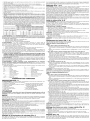
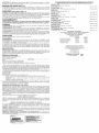
To Change Blades (Fig. 7, 8)
The planer is capable of using high-speed steel and carbide blades. Be sure to check the planer
to verify which blade it is fitted with.
HIGH-SPEED STEEL BLADES (FIG. 7)
D26676
1. To Remove Blade from Planer (Fig. 7B)
a. Loosen and remove the three hex head screws (O) with the 9 mm hex wrench provided.
Remove the drum cover (P) from the drum (Q).
b. Cautiously remove the guide bar/high-speed steel blade assembly (V, U, T).
2. To Adjust Blade Using Gauge Plate (provided with tool) (Fig. 7C)
a. Place the guide bar/high-speed steel blade assembly on the gauge plate (R) with the
cutting edge of the high-speed steel blade flush against the gauge plate inside wall (S).
The heel of the guide bar (T) will overlap the end of the gauge plate (R).
b. Loosen the two cross-shaped screws (U) with the wrench provided.
c. Simultaneously push the high-speed steel blade (V) and the guide bar (T) into the gauge
plate inside wall (S), making sure that the blade is held firmly against the gauge plate
inside wall (S) and securely tighten cross-shaped screws (U).
3. To Reinstall Blade (Fig. 7A, 7B)
a. Cautiously remove the adjusted guide bar/high-speed steel blade assembly from the
gauge plate (R) and place the heel of the guide bar (T) into the groove in the drum (Q).
b. Set the drum cover (P) over the adjusted guide bar/high-speed steel blade assembly and
securely tighten the three hex screws (O) to the drum.
4. Repeat procedure for the other blade.
NOTE: If your planer is not fitted with high-steel blades, the sharpening holder (Y) required to
sharpen high-speed blades is available at additional cost from your local DEWALT authorized
service center.
REVERSIBLE CARBIDE BLADES (FIG. 8)
D26677
1. To Remove Blade from Planer (Fig. 8B)
a. Loosen and remove the three hex head screws (O) with the 9 mm hex wrench provided.
Remove the drum cover (P) from the drum (Q).
b. Remove the blade carrier/guide bar assembly (T, U, X, W). Carefully remove the carbide
blade (W).
2. To Adjust Blade Using Gauge Plate (provided with tool) (Fig. 8C)
a. Cautiously place the carbide blade on the gauge plate (R) with the grooved side of the
carbide blade facing up. Either edge of the reversible carbide blade can be set flush
against the gauge plate inside wall (S).
b. Place the blade carrier/guide bar assembly on the blade so that the rib on the blade
carrier (X) fits into the groove on the carbide blade (W). The heel of the blade carrier (X)
will overlap the end of the gauge plate (R).
c. Loosen the two cross-shaped screws (U) with the wrench provided.
d. Simultaneously push the blade carrier (X) and the guide bar (T) into the gauge plate inside
wall (S), making sure that the carbide blade (W) is held firmly against the gauge plate
inside wall (S) and securely tighten the two cross-shaped screws (U).
3. To Reinstall Blade (Fig. 8A, 8B)
a. Remove the adjusted blade carrier/guide bar assembly from the gauge plate (R) and
place the heel of the guide bar (T) into the groove on the drum (Q).
FIG. 1
A
C
M G
FIG. 2
CORRECT
CORRECT
CORRECTO
FIG. 3 FIG. 4
INCORRECT INCORRECT
INCORRECT INCORRECT
INCORRECTO INCORRECTO
FIG. 5
FIG. 6
FIG. 7 HIGH-SPEED STEEL BLADE /
LAME EN ACIER ,&,COUPE RAPIDE / HOJA DE ACERO DE ALTA VELOCIDAD
T Q
P
FIG. 7A
Q V
T
FIG. 7B
U
T V
FIG. 7C
FIG. 8 CARBIDE BLADE / LAME AU CARBURE / HOJA DE CARBURO
T Q
u
o /
w
FIG.8A
W
T
FIG. 8B
O
R
U T W
FIG. 8C
FIG.9 Y
\
FIG. 10
Z
BLADE EDGE
BORD DE LAME
BORDE DE LA HOJA
FIG. 11
A1

b. Place the drum cover (P) over the blade carrier/guide bar assembly. Loosely screw the
three hex screws (O) into the drum (Q) so that there is a small gap between the drum
and the blade carrier (X).
c. Slide the carbide blade between the drum (Q) and the blade carrier (X) so that the rib on
the blade carrier sets into the groove in the blade.
d. Center the carbide blade (W) under the blade carrier (X) making sure the blade is clear
of the tool housing on both sides.
e. Securely tighten the three hex screws (O) to the drum.
4. Repeat procedure for the other blade.
NOTE: If your planer is not fitted with carbide blades, the blade carrier (X) required for carbide
blades is available at additional cost from your local DEWALT authorized service center.
Sharpening High-Speed Steel Blades (Fig. 9)
NOTE: Carbide blades cannot be sharpened.
1. Fasten the blades to the sharpening holder (Y). Make sure both blade edges (V) are facing
the same direction.
2. Place the blade edges so they rest flat on the grinding stone (not included).
3. Firmly grip the sharpening holder and move it back and forward to sharpen the blades (V).
Kickstand (Fig. 10)
Your planer isequipped with a kickstand (Z) that automatically lowers when the tool is liftedfrom
the work surface allowing the planer to set on the work surface without the blade touching it
When planing, the kickstand raises as the tool is pushed forward through the material.
A CAUTION: Do not lock the trigger switch on and engage the kickstand. The vibration of the
running motor will cause the planer to move, possibly falling from the workpiece.
Edge Chamfering (Fig. 11)
Your planer has a precision machined chamfering groove (A1) in the front shoe for planing along
a corner of the wood. The width of the groove is 4.5 to 8 mm. It's a good idea to try a piece of
scrap wood before doing finish work.
Dust Adapter (Fig. 1)
A dual adapter (L) is available for the hand planer. The adapter can be attached to both 1"
(inside diameter) and 35 mm (outside diameter) vacuum hose connectors for dust collection.
Insert the adapter (L) onto chip discharge chute (K) and attach the appropriate vacuum hose
connector to the adapter.
If the adapter is not included with your planer please contact your local DEWALT authorized
service center to obtain one at additional cost.
MAINTENANCE
_ WARNING: To reduce the risk of serious personal injury, turn tool off and disconnect tool
from power source before making any adjustments or removing/installing attachments
or accessories.
Cleaning
A WARNING: Clean the chip discharge chute (K) regularly. ALWAYS WEAR SAFETY
GLASSES.
AWARNING: Blow dirt and dust out of all air vents with dry air at least once a week. Wear
proper ANSI Z87.1 (CAN/CSA Z94.3) eye protection and proper NIOSH/OSHA/MSHA
respiratory protection when performing this.
A WARNING: Never use solvents or other harsh chemicals for cleaning the non-metallic parts
of the tool. These chemicals may weaken the plastic materials used in these parts. Use a cloth
dampened only with water and mild soap. Never let any liquid get inside the tool; never immerse
any part of the tool into a liquid.
Lubrication
Your power tool requires no additional lubrication.
Accessories
A WARNING: Since accessories, other than those offered by DEWALT, have not been tested
with this product, use of such accessories with this tool could be hazardous. To reduce the risk
of injury, only DEWALT, recommended accessories should be used with this product.
Recommended accessories for use with your tool are available at extra cost from your local dealer
or authorized service center. If you need assistance in locating any accessory, please contact
DEWALT Industrial Tool Co., 701 East Joppa Road, Baltimore, MD 21286, call 1-800-4-DEWALT
(1-800-433-9258) or visit our website www.dewalt.com.
Repairs
To assure product SAFETY and RELIABILITY, repairs, maintenance and adjustments (including
brush inspection and replacement) should be performed by a DEWALT factory service center,
a DEWALT authorized service center or other qualified service personnel. Always use identical
replacement parts.
Three Year Limited Warranty
DEWALT will repair, without charge, any defects due to faulty materials or workmanship for
three years from the date of purchase. This warranty does not cover part failure due to normal
wear or tool abuse. For further detail of warranty coverage and warranty repair information, visit
www.dewalt.com or call 1-800-4-DEWALT (1-800-433-9258). This warranty does not apply to
accessories or damage caused where repairs have been made or attempted by others. This
warranty gives you specific legal rights and you may have other rights which vary in certain
states or provinces.
In addition to the warranty, DEWALT tools are covered by our:
1YEAR FREE SERVICE
DEWALT will maintain the tool and replace worn parts caused by normal use, for free, any time
during the first year after purchase.
90 DAY MONEY BACK GUARANTEE
If you are not completely satisfied with the performance of your DEWALT Power Tool, Laser, or
Nailer for any reason, you can return it within 90 days from the date of purchase with a receipt
for a full refund - no questions asked.
LATIN AMERICA: This warranty does not apply to products sold in Latin America. For products
sold in Latin America, see country specific warranty information contained either in the
packaging, call the local company or see website for warranty information.
FREE WARNING LABEL REPLACEMENT: If your warning labels become illegible or are
missing, call 1-800-4-DEWALT (1-800-433-9258) for a free replacement.
fg_XX× F[ANER "]
SE"._ /
_,0OEUUCET.E |
RISK DF INJURY, USEH _
MUSTREAD iNSTRUCTiON MANUAL ALWAYS USE
PROPEREYE AND RESPIRATORY PROTECTION,
DEWALT INDUSTFIIAL TOOL CO., BALTiMOF_E, MD 21286 USA
_www,O EWA LT,com
PARA EL MANEJO
SEGURO LEA EL
MANUAL DE JNSTRUCCJONES,SiEMPRE SE DEBERA
LLEVAR [A PROTECCJI)NAPRDPiADA PARA LAVISTA Y
PARA [AS VJASRESPJRATORJAS, _,TITRE
_ PREVENTIF, LiRE
LE GUIDE. ILFAUT TDUJOURS PORTER DEL'EQUiPEMENT
DE PROTECTION OCULAJREETRESPJRATOJRE
APPROPRJE.
Ddfinitions : lignes directrices en
matidre de sdcuritd
Les d6finitions ci-dessous d6crivent le niveau de danger pour chaque mot-indicateur
employ& Veuillez lire le mode d'emploi et porter une attention particuli_re & ces
symboles.
i_DANGER : indique une situation dangereuse imminente qui, si elle n'est pas
evitee, causera la mort ou des blessures graves.
i_AVERTISSEMENT : indique une situation potentiellement dangereuse qui, si eile
n'est pas evitee, pourrait se solder par un deces ou des blessures graves.
,&ATTENTION : indique une situation potentiellement dangereuse qui, si elle n'est
pas evitee pourrait se solder par des blessures mineures ou moderees.
AVIS : indique une pratique ne posant aucun risque de dommages corporels mais
qui par contre, si rien n'est fair pour I'eviter, pourrait poser des risques de dommages
materiels.
".. J
POUR TOUTE QUESTION OU TOUT COMMENTAIRE RELATIF ,&, CET OUTIL OU A
PROPOS DE TOUT AUTRE OUTIL DEWALT,COMPOSER SANS FRAIS LE : 1-800-4-DEWALT
(1-800-433-9258).
AVERTISSEMENT : afin de reduire le risque de blessures, lire le mode d'emploi de
I'outil.
Avertissements de sdcuritd gdndraux pour les outils
dlectriques
_ AVERTISSEMENT! Life tous les avertissements de securite et les directives. Le
non-respect des avertissements et des directives pourrait se solder par un choc
electrique, un incendie et/ou une blessure grave.
CONSERVER TOUS LES AVERTISSEMENTS ET TOUTES
LES DIRECTIVES POUR UN USAGE ULTERIEUR
Le terme , outil electrique _ cite dans les avertissements se rapporte a votre outil electrique
alimentation sur secteur (avec ill) ou par piles (sans ill).
1) SI_CURITI_ DU LIEU DE TRAVAIL
a) Tenir I'aire de travail propre et bien eclairee. Les lieux encombres ou sombres sont
propices aux accidents.
b) Ne pas faire fonctionner d'outils electriques clans un milieu deflagrant, tel qu'en
presence de liquides, de gaz ou de poussieres inflammables. Les outils electriques
produisent des etincelles qui pourraient enflammer la poussiere ou les vapeurs.
c) Eloigner les enfants et les personnes a proximite pendant I'utilisation d'un outil
electrique. Une distraction pourrait en faire perdre la maftrise a I'utilisateur.
2) SI_CURITI_ EN MATIERE D'I_LECTRICITI_
a) Les fiches des outils electriques doivent correspondre a la prise. Ne jamais
modifier la fiche d'aucune fa_on. Ne jamais utiliser de fiche d'adaptation avec un
outil electrique mis a la terre. Le risque de choc electrique sera reduit par I'utilisation de
fiches non modifiees correspondant a la prise.
b) E:viter tout contact physique avec des surfaces mises a la terre comme des tuyaux,
des radiateurs, des cuisinieres et des refrigerateurs. Le risque de choc electrique est
plus eleve si votre corps est mis a la terre.
c) Ne pas exposer les outils electriques a la pluie ou a I'humidite. La penetration de I'eau
dans un outil electrique augmente le risque de choc electrique.
d) Ne pas utiliser le cordon de fa_on abusive. Ne jamais utiliser le cordon pour
transporter, tirer ou debrancher un outil electrique. Tenir le cordon eloigne de
la chaleur, de I'huile, des bords tranchants et des pieces mobiles. Les cordons
endommages ou enchev6tres augmentent les risques de choc electrique.
e) Pour I'utilisation d'un outil electrique a I'exterieur, se servir d'une railonge
convenant a cette application. L'utilisation d'une rallonge congue pour I'exterieur reduira
les risques de choc electrique.
f) S'il est impossible d'eviter I'utilisation d'un outil electrique clans un endroit humide,
brancher I'outil dans une prise ou sur un circuit d'alimentation dotes d'un disjoncteur de
fuite a la terre (GFCI). L'utilisation de ce type de disjoncteur reduit les risques de choc
electrique.
3) SI_CURITI_ PERSONNELLE
a) Etre vigilant, surveiller le travail effectue et faire preuve de jugement Iorsqu'un outil
electrique est utilise. Ne pas utiliser d'outil electrique en cas de fatigue ou sous
I'influence de drogues, d'alcool ou de medicaments. Un simple moment d'inattention
en utilisant un outil electrique peut entrafner des blessures corporelles graves.
b) Utiliser des equipements de protection individueile. Toujours porter une protection
oculaire. L'utilisation d'equipements de protection comme un masque antipoussiere, des
chaussures antiderapantes, un casque de securite ou des protecteurs auditifs Iorsque la
situation le requiert reduira les risques de blessures corporelles.
c) EmpGcher lee demarrages intempestifs. S'assurer que I'interrupteur se trouve a la
position d'arrGt avant de relier I'outil a une source d'alimentation et/ou d'inserer un
bloc-piles, de ramasser ou de transporter I'outil. Transporter un outi/ e/ectrique a/ors
que le doigt repose sur I'interrupteur ou brancher un outil electrique dont I'interrupteur est
la position de marche risque de provoquer un accident.
d) Retirer route cle de reglage ou cle avant de demarrer I'outil. Une cle ou une cle de
reglage attachee a une pattie pivotante de Ibutil electrique peut provoquer des blessures
corporelles.
e) Ne pas trop tendre les bras. Conserver son equilibre en tout temps. Cela permet de
mieux maftriser Ibutil electrique dans les situations imprevues.
f) S'habiller de maniere appropriee. Ne pas porter de v6tements amples ni de bijoux.
Carder les cheveux, les vGtements et les gants a I'ecart des pieces mobiles. Les
v6tements amples, les bijoux ou les cheveux longs risquent de rester coinces dans les
pieces mobiles.
g) Si des composants sont fourn is pour leraccordement de dispositifs de depoussierage
et de ramassage, s'assurer que ceux-ci sont bien raccordes et utilises. L'utilisation
d'un dispositif de depoussierage peut reduire les dangers engendres par les poussieres.
4) UTILISATION ET ENTRETIEN D'UN OUTIL #LECTRIQUE
a) Ne pas forcer un outil electrique. Utiliser I'outil electrique approprie a I'application.
L'outil electrique approprie effectuera un meilleur travail, de fagon plus s_re et a la vitesse
pour laquelle il a ere congu.
b) Ne pas utiliser un outil electrique dont I'interrupteur est defectueux. Tout outil
electrique dont I'interrupteur est defectueux est dangereux et doit 6tre repare.
c) Debrancher la fiche de la source d'alimentation et/ou du bloc-piles de I'outil
electrique avant de faire tout reglage ou changement d'accessoire ou avant de
ranger I'outil. Ces mesures preventives reduisent les risques de demarrage accidentel
de I'outil electrique.
d) Ranger les outils electriques hors de la portee des enfants et ne permettre
aucune personne n'etant pas familiere avec un outil electrique ou son mode
d'emploi d'utiliser cet outil. Les outils electriques deviennent dangereux entre les mains
d'utilisateurs inexperimentes.
e) Entretien des outils electriques. Wrifier si les pieces mobiles sont mal alignees ou
coincees, si des pieces sont brisees ou presentent route autre condition susceptible
de nuire au bon fonctionnement de I'outil electrique. En cas de dommage, faire
reparer I'outil electrique avant route nouveile utilisation. Beaucoup d'accidents sont
causes par des outils electriques mal entretenus.
f) S'assurer que les outils de coupe sont aiguises et propres. Les outils de coupe
bien entretenus et aff_tes sont moins susceptibles de se coincer et sont plus faciles
maftriser.
g) Utiliser I'outil electrique, les accessoires, les forets, etc. conformement aux
presentes directives en tenant compte des conditions de travail et du travail
effectuer. L'utilisation d'un outil electrique pour route operation autre que celle pour
laquelle il a ere congu est dangereuse.
5) RI-PARATION
a) Faire reparer I'outil electrique par un reparateur professionnel en n'utilisant que des
pieces de rechange identiques. Cela permettra de maintenir une utilisation securitaire
de I'outil electrique.
Consignes additionnelles de s_curit_ propres aux
raboteuses
• Attendre I'arrGt complet de I'organe de coupe avant de poser I'outil sur une surface
quelconque. L'organe de coupe a nu pourrait attaquer la surface et causer la perte de
contr61e de I'outil et des dommages corporels graves.
• Utiliser des serre-joints, ou tout autre moyen, pour fixer et immobiliser le materiau
sur une surface stable. Tenir la piece a la main ou contre son corps offre une stabilite
insuffisante qui pourrait vous en faire perdre le contr61e.
• S'assurer que le voltage utilise correspond bien a celui indique sur la plaque signaletique.
• S'assurer que I'interrupteur de I'outil est en position d'arr6t avant de le brancher sur le
secteur.
• S'assurer de mettre immediatement I'interrupteur en position d'ARRET si Ibutil s'enraye.
• S'assurer que Ibutil est regle a la bonne profondeur de coupe avant de le mettre en
MARCHE.
• S'assurer d'effectuer une bonne maintenance de Ibutil. Suivre route instruction relative a la
lubrification et au changement d'accessoire.
• Rester vigilant- ne jamais utiliser I'appareil en cas de fatigue ou sous I'influence de drogue,
alcool ou medicaments.
• S'assurer de bien ranger Ibutil dans un endro# propre et sec apres I'avoir debranche.
• Ne pas I'utiliser dans un environnement dangereux. Ne pas utiliser Ibutil a proximite de
substances inflammables, sur des lieux humides ou detrempes, ou I'exposer a la pluie.
• S'assurer que I'organe de coupe a bien ere monte suivant les instructions du manuel, et que
route vis sur I'appareil est bien serree avant de le brancher.
• Maintenir tout event libre de route obstruction pour assurer le refroidissement correct du
moteur.
Page is loading ...
Page is loading ...
Page is loading ...
Page is loading ...
-
 1
1
-
 2
2
-
 3
3
-
 4
4
-
 5
5
-
 6
6
-
 7
7


DeWalt D26677K TYPE 1 Owner's manual
- Category
- Power tools
- Type
- Owner's manual
Ask a question and I''ll find the answer in the document
Finding information in a document is now easier with AI
in other languages
Related papers
Other documents
-
Ryobi P611 Owner's manual
-
-
-
-
Craftsman CMEW300 Owner's manual
-
-
Craftsman 315.173700 Owner's manual
-
-
RIDGID R8481 User manual
-
RIDGID R8481 18-Volt OCTANE Cordless Brushless 3-1-4 in. Hand Planer User manual