Page is loading ...

Installation Guide
www.edge-core.com
ES3528MV2
ES3528MV2-DC
28-Port Fast Ethernet
Layer 2 Switch

I
NSTALLATION
G
UIDE
FAST ETHERNET LAYER 2 SWITCH
Layer 2 Switch with
24 10/100BASE-TX (RJ-45) Ports,
and 4 Combination Gigabit (RJ-45/SFP) Ports
ES3528MV2
ES3528MV2-DC
E122011-CS-R02
xxxxxxxxxxxxx

– 5 –
COMPLIANCES AND SAFETY
STATEMENTS
FCC - CLASS A
This equipment has been tested and found to comply with the limits for a Class A
digital device, pursuant to part 15 of the FCC Rules. These limits are designed to
provide reasonable protection against harmful interference when the equipment
is operated in a commercial environment. This equipment generates, uses, and
can radiate radio frequency energy and, if not installed and used in accordance
with the instruction manual, may cause harmful interference to radio
communications. Operation of this equipment in a residential area is likely to
cause harmful interference in which case the user will be required to correct the
interference at his own expense.
You are cautioned that changes or modifications not expressly approved by the
party responsible for compliance could void your authority to operate the
equipment.
You may use unshielded twisted-pair (UTP) for RJ-45 connections - Category 3
or better for 10 Mbps connections, Category 5 or better for 100 Mbps
connections, Category 5, 5e, or 6 for 1000 Mbps connections. For fiber optic
connections, you may use 50/125 or 62.5/125 micron multimode fiber or 9/125
micron single-mode fiber.
JAPAN VCCI CLASS A

C
OMPLIANCES
AND
S
AFETY
S
TATEMENTS
– 6 –
CE MARK DECLARATION OF CONFORMANCE FOR EMI AND SAFETY (EEC)
This information technology equipment complies with the requirements of the
Council Directive 89/336/EEC on the Approximation of the laws of the Member
States relating to Electromagnetic Compatibility and 73/23/EEC for electrical
equipment used within certain voltage limits and the Amendment Directive 93/
68/EEC. For the evaluation of the compliance with these Directives, the following
standards were applied:
RFI Emission:
◆ Limit according to EN 55022:2007, Class A/B
◆ Limit for harmonic current emission according to EN 61000-3-2:2006,
Class A
◆ Limitation of voltage fluctuation and flicker in low-voltage supply
system according to EN 61000-3-3:2005
Immunity:
◆ Product family standard according to EN 55024:2001 + A2:2003
◆ Electrostatic Discharge according to IEC 61000-4-2:2008
◆ Radio-frequency electromagnetic field according to IEC 61000-4-
3:2007
◆ Electrical fast transient/burst according to IEC 61000-4-4:2004
◆ Surge immunity test according to IEC 61000-4-5:2005
◆ Immunity to conducted disturbances, Induced by radio-frequency
fields: IEC 61000-4-6:2008
◆ Power frequency magnetic field immunity test according to IEC
61000-4-8:2001
◆ Voltage dips, short interruptions and voltage variations immunity test
according to IEC 61000-4-11:2004
LVD:
◆ EN 60950-1:2006+A11:2009

C
OMPLIANCES
AND
S
AFETY
S
TATEMENTS
– 7 –
SAFETY COMPLIANCE
Warning: Fiber Optic Port Safety
Avertissment: Ports pour fibres optiques - sécurité sur le plan optique
Warnhinweis: Faseroptikanschlüsse - Optische Sicherheit
PSE ALARM
本製品に同梱いたしております電源コードセットは、
本製品専用です。本電源コードセットは、本製品以外の
製品並びに他の用途でご使用いただくことは出来ません。
製品本体に同梱された電源コードセットを利用し、他製品
の電源コードセットを使用しないで下さい。
When using a fiber optic port, never look at the transmit laser while it
is powered on. Also, never look directly at the fiber TX port and fiber
cable ends when they are powered on.
Ne regardez jamais le laser tant qu'il est sous tension. Ne regardez
jamais directement le port TX (Transmission) à fibres optiques et les
embouts de câbles à fibres optiques tant qu'ils sont sous tension.
Niemals ein Übertragungslaser betrachten, während dieses
eingeschaltet ist. Niemals direkt auf den Faser-TX-Anschluß und auf
die Faserkabelenden schauen, während diese eingeschaltet sind.
CLASS I
LASER DEVICE
DISPOSITIF LASER
DE CLASSE I
LASERGER
DER KLASSE I
ÄT

C
OMPLIANCES
AND
S
AFETY
S
TATEMENTS
– 8 –
POWER CORD SAFETY
Please read the following safety information carefully before installing
the switch:
WARNING:
Installation and removal of the unit must be carried out by qualified
personnel only.
◆ The unit must be connected to an earthed (grounded) outlet to comply with
international safety standards.
◆ Do not connect the unit to an A.C. outlet (power supply) without an earth
(ground) connection.
◆ The appliance coupler (the connector to the unit and not the wall plug) must
have a configuration for mating with an EN 60320/IEC 320 appliance inlet.
◆ The socket outlet must be near to the unit and easily accessible. You can
only remove power from the unit by disconnecting the power cord from the
outlet.
◆ This unit operates under SELV (Safety Extra Low Voltage) conditions
according to IEC 60950. The conditions are only maintained if the
equipment to which it is connected also operates under SELV conditions.
France and Peru only
This unit cannot be powered from IT
†
supplies. If your supplies are of IT type,
this unit must be powered by 230 V (2P+T) via an isolation transformer ratio
1:1, with the secondary connection point labelled Neutral, connected directly to
earth (ground).
†
Impédance à la terre
I
MPORTANT
!
Before making connections, make sure you have the correct cord
set. Check it (read the label on the cable) against the following:

C
OMPLIANCES
AND
S
AFETY
S
TATEMENTS
– 9 –
Veuillez lire à fond l'information de la sécurité suivante avant d'installer
le Switch:
AVERTISSEMENT:
L’installation et la dépose de ce groupe doivent être confiés à
un personnel qualifié.
◆ Ne branchez pas votre appareil sur une prise secteur (alimentation
électrique) lorsqu'il n'y a pas de connexion de mise à la terre (mise à la
masse).
◆ Vous devez raccorder ce groupe à une sortie mise à la terre (mise à la
masse) afin de respecter les normes internationales de sécurité.
◆ Le coupleur d’appareil (le connecteur du groupe et non pas la prise murale)
doit respecter une configuration qui permet un branchement sur une entrée
d’appareil EN 60320/IEC 320.
Power Cord Set
U.S.A. and Canada The cord set must be UL-approved and CSA certified.
The minimum specifications for the flexible cord are:
- No. 18 AWG - not longer than 2 meters, or 16 AWG.
- Type SV or SJ
- 3-conductor
The cord set must have a rated current capacity of at least 10 A
The attachment plug must be an earth-grounding type with NEMA
5-15P (15 A, 125 V) or NEMA 6-15P (15 A, 250 V) configuration.
Denmark The supply plug must comply with Section 107-2-D1, Standard
DK2-1a or DK2-5a.
Switzerland The supply plug must comply with SEV/ASE 1011.
U.K. The supply plug must comply with BS1363 (3-pin 13 A) and be fitted
with a 5 A fuse which complies with BS1362.
The mains cord must be <HAR> or <BASEC> marked and be of type
HO3VVF3GO.75 (minimum).
Europe The supply plug must comply with CEE7/7 (“SCHUKO”).
The mains cord must be <HAR> or <BASEC> marked and be of type
HO3VVF3GO.75 (minimum).
IEC-320 receptacle.

C
OMPLIANCES
AND
S
AFETY
S
TATEMENTS
– 12 –
WARNINGS AND CAUTIONARY MESSAGES
ENVIRONMENTAL STATEMENTS
The manufacturer of this product endeavours to sustain an environmentally-
friendly policy throughout the entire production process. This is achieved though
the following means:
◆ Adherence to national legislation and regulations on environmental
production standards.
◆ Conservation of operational resources.
◆ Waste reduction and safe disposal of all harmful un-recyclable by-products.
◆ Recycling of all reusable waste content.
◆ Design of products to maximize recyclables at the end of the product’s life
span.
◆ Continual monitoring of safety standards.
W
ARNING
:
This product does not contain any serviceable user parts.
W
ARNING
:
Installation and removal of the unit must be carried out by
qualified personnel only.
W
ARNING
:
When connecting this device to a power outlet, connect the
field ground lead on the tri-pole power plug to a valid earth ground line
to prevent electrical hazards.
W
ARNING
:
This switch uses lasers to transmit signals over fiber optic
cable. The lasers are compliant with the requirements of a Class 1
Laser Product and are inherently eye safe in normal operation.
However, you should never look directly at a transmit port when it is
powered on.
C
AUTION
:
Wear an anti-static wrist strap or take other suitable
measures to prevent electrostatic discharge when handling this
equipment.
C
AUTION
:
Do not plug a phone jack connector in the RJ-45 port. This
may damage this device.
C
AUTION
:
Use only twisted-pair cables with RJ-45 connectors that
conform to FCC standards.

C
OMPLIANCES
AND
S
AFETY
S
TATEMENTS
– 13 –
END OF PRODUCT LIFE SPAN
This product is manufactured in such a way as to allow for the recovery and
disposal of all included electrical components once the product has reached the
end of its life.
MANUFACTURING MATERIALS
There are no hazardous nor ozone-depleting materials in this product.
DOCUMENTATION
All printed documentation for this product uses biodegradable paper that
originates from sustained and managed forests. The inks used in the printing
process are non-toxic.

C
OMPLIANCES
AND
S
AFETY
S
TATEMENTS
– 14 –

– 15 –
ABOUT THIS GUIDE
PURPOSE
This guide details the hardware features of the switch, including the physical and
performance-related characteristics, and how to install the switch.
AUDIENCE
The guide is intended for use by network administrators who are responsible for
installing and setting up network equipment; consequently, it assumes a basic
working knowledge of LANs (Local Area Networks).
CONVENTIONS
The following conventions are used throughout this guide to show information:
RELATED PUBLICATIONS
The following publication gives specific information on how to operate and use
the management functions of the switch:
The Management Guide
Also, as part of the switch’s software, there is an online web-based help that
describes all management related features.
N
OTE
:
Emphasizes important information or calls your attention to
related features or instructions.
C
AUTION
:
Alerts you to a potential hazard that could cause loss of data,
or damage the system or equipment.
W
ARNING
:
Alerts you to a potential hazard that could cause personal
injury.

A
BOUT
T
HIS
G
UIDE
– 16 –
REVISION HISTORY
This section summarizes the changes in each revision of this guide.
DECEMBER 2011 REVISION
This is the second revision of this guide. This revision includes the following
changes:
◆ Added information for the DC version of the switch.
NOVEMBER 2011 REVISION
This is the first revision of this guide.

– 17 –
CONTENTS
COMPLIANCES AND SAFETY STATEMENTS 5
A
BOUT THIS GUIDE 15
C
ONTENTS 17
T
ABLES 21
F
IGURES 23
1I
NTRODUCTION 25
Overview 25
Switch Architecture 26
Network Management Options 26
Description of Hardware 26
10/100BASE-T Ports 26
SFP Slots 27
Port and System Status LEDs 27
Power Supply Socket 29
Application Examples 30
Network Aggregation Plan 30
Remote Connection with Fiber Cable 31
2INSTALLING THE SWITCH 33
Selecting a Site 33
Ethernet Cabling 34
Equipment Checklist 35
Package Contents 35
Optional Rack-Mounting Equipment 35
Mounting 36

C
ONTENTS
– 18 –
Rack Mounting 36
Desktop or Shelf Mounting 38
Installing an Optional SFP Transceiver 39
Connecting to a Power Source 40
Connecting DC Power 40
Connecting AC Power 42
Connecting to the Console Port 43
Wiring Map for Serial Cable 43
3MAKING NETWORK CONNECTIONS 45
Connecting Network Devices 45
Twisted-Pair Devices 45
Cabling Guidelines 45
Connecting to PCs, Servers, Hubs and Switches 46
Network Wiring Connections 47
Fiber Optic SFP Devices 48
Connectivity Rules 49
1000BASE-T Cable Requirements 49
1000 Mbps Gigabit Ethernet Collision Domain 50
100 Mbps Fast Ethernet Collision Domain 51
10 Mbps Ethernet Collision Domain 51
Cable Labeling and Connection Records 51
ATROUBLESHOOTING 53
Diagnosing Switch Indicators 53
Power and Cooling Problems 54
Installation 54
In-Band Access 54
BCABLES 55
Twisted-Pair Cable and Pin Assignments 55
10BASE-T/100BASE-TX Pin Assignments 56
Straight-Through Wiring 56


C
ONTENTS
– 20 –

– 21 –
TABLES
Table 1: Port Status LEDs 27
Table 2: System Status LEDs 28
Table 3: Console Cable Wiring 43
Table 4: Maximum 1000BASE-T Gigabit Ethernet Cable Length 50
Table 5: Maximum 1000BASE-SX Gigabit Ethernet Cable Lengths 50
Table 6: Maximum 1000BASE-LX Gigabit Ethernet Cable Length 50
Table 7: Maximum 1000BASE-LH Gigabit Ethernet Cable Length 50
Table 8: Maximum Fast Ethernet Cable Lengths 51
Table 9: Maximum Ethernet Cable Length 51
Table 10: Troubleshooting Chart 53
Table 11: 10/100BASE-TX MDI and MDI-X Port Pinouts 56
Table 12: 1000BASE-T MDI and MDI-X Port Pinouts 58
Table 13: Fiber Standards 59

– 23 –
FIGURES
Figure 1: Front and Rear Panels 25
Figure 2: Port Status LEDs 27
Figure 3: System Status LED 28
Figure 4: AC Power Supply Socket 29
Figure 5: DC Power Supply Socket 29
Figure 6: Network Aggregation Plan 31
Figure 7: Remote Connections with Fiber Cable 32
Figure 8: RJ-45 Connections 34
Figure 9: Attaching the Brackets 37
Figure 10: Installing the Switch in a Rack 37
Figure 11: Attaching the Adhesive Feet 38
Figure 12: Inserting an SFP Transceiver into a Slot 39
Figure 13: DC Plug Connections 41
Figure 14: DC Power Socket 42
Figure 15: AC Power Socket 42
Figure 16: Serial Port (DB-9 DTE) Pin-Out 43
Figure 17: Making Twisted-Pair Connections 46
Figure 18: Network Wiring Connections 47
Figure 19: Making Fiber Port Connections 49
Figure 20: RJ-45 Connector Pin Numbers 55
Figure 21: Straight-through Wiring 57
Figure 22: Crossover Wiring 57

– 25 –
1 INTRODUCTION
OVERVIEW
The ES3528MV2 and ES3528MV2-DC are intelligent switches with 24 10/
100BASE-T ports, and four Gigabit combination ports
1
that are comprised of an
RJ-45 port and an SFP transceiver slot. There is also an SNMP-based
management agent embedded on the main board. This agent supports both in-
band and out-of-band access for managing the switch.
These switches provide a broad range of powerful features for Layer 2 switching,
delivering reliability and consistent performance for your network traffic. They
bring order to poorly performing networks by segregating them into separate
broadcast domains with IEEE 802.1Q compliant VLANs, and empower
multimedia applications with multicast switching and CoS services.
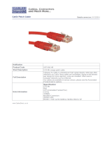
Figure 1: Front and Rear Panels
1. RJ-45 ports shared with a SFP tranceiver slots. If an SFP transceiver is plugged in,
the corresponding RJ-45 port is disabled.
ES3528MV2
1 3 5 7 9 11131517192123
25 27
26 282 4 6 8 10 12 14 16 18 20 22 24
Console
PWR
DIAG
1000M
1000M
Link/ACT
Link/ACT
10/100 Mbps RJ-45 Ports
Console
Port
System Indicators
Combination
Gigabit Ports
AC Power Socket
Port Status
Indicators
DC Power Socket

C
HAPTER
1
| Introduction
Description of Hardware
– 26 –
SWITCH ARCHITECTURE
The switch employs a wire-speed, non-blocking switching fabric. This permits
simultaneous wire-speed transport of multiple packets at low latency on all
ports. The switch also features full-duplex capability on all ports, which
effectively doubles the bandwidth of each connection.
The switch uses store-and-forward switching to ensure maximum data integrity.
With store-and-forward switching, the entire packet must be received into a
buffer and checked for validity before being forwarded. This prevents errors
from being propagated throughout the network.
NETWORK MANAGEMENT OPTIONS
This switch contains a comprehensive array of LEDs for “at-a-glance” monitoring
of network and port status. It also includes a management agent that allows you
to configure or monitor the switch using its embedded management software, or
via SNMP applications. To manage a switch, you can make a direct connection to
the RS-232 console port (out-of-band), or you can manage it through a network
connection (in-band) using Telnet, the on-board Web agent, or Windows-based
network management software.
For a detailed description of the switch’s software features, refer to the
Management Guide.
DESCRIPTION OF HARDWARE
10/100BASE-T PORTS
This switch contains 24 RJ-45 ports that operate at 10 Mbps or 100 Mbps, half or
full duplex. Because all ports on both switches support automatic MDI/MDI-X
operation, you can use straight-through cables for all network connections to
PCs or servers, or to other switches or hubs. (See “Twisted-Pair Cable and Pin
Assignments” on page 55.)
Each of these ports support auto-negotiation, so the optimum transmission
mode (half or full duplex), and data rate (10 or 100 Mbps) can be selected
automatically. If a device connected to one of these ports does not support auto-
negotiation, the communication mode of that port can be configured manually.
/