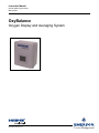
Emerson OxyBalance User manual
- Category
- Oxygen Equipment
- Type
- User manual
This manual is also suitable for

http://www.raihome.com
Instruction Manual
IM-106-4050 Original Issue
March 2006
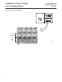
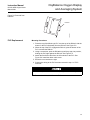
OxyBalance
Oxygen Display and Averaging System
Page is loading ...

Instruction Manual
IM-106-4050 Original Issue
March 2006
TOC-1
OxyBalance Oxygen Display
and Averaging System
Table of Contents
Essential Instructions. . . . . . . . . . . . . . . . . . . . . . . . . . . . . . . . . . . . . . . . i
Preface . . . . . . . . . . . . . . . . . . . . . . . . . . . . . . . . . . . . . . . . . . . . . . . . . . ii
Definitions . . . . . . . . . . . . . . . . . . . . . . . . . . . . . . . . . . . . . . . . . . . . . . . . ii
Symbols . . . . . . . . . . . . . . . . . . . . . . . . . . . . . . . . . . . . . . . . . . . . . . . . . . ii
SECTION 1
Description
Component Checklist. . . . . . . . . . . . . . . . . . . . . . . . . . . . . . . . . . . . . . 1-1
Part Numbers. . . . . . . . . . . . . . . . . . . . . . . . . . . . . . . . . . . . . . . . . . . . 1-1
System Overview. . . . . . . . . . . . . . . . . . . . . . . . . . . . . . . . . . . . . . . . . 1-2
General. . . . . . . . . . . . . . . . . . . . . . . . . . . . . . . . . . . . . . . . . . . . . . 1-2
OxyBalance System Features . . . . . . . . . . . . . . . . . . . . . . . . . . . . 1-2
Physical Description . . . . . . . . . . . . . . . . . . . . . . . . . . . . . . . . . . . . 1-3
Specifications. . . . . . . . . . . . . . . . . . . . . . . . . . . . . . . . . . . . . . . . . . . . 1-5
SECTION 2
Installation
Overview . . . . . . . . . . . . . . . . . . . . . . . . . . . . . . . . . . . . . . . . . . . . . . . 2-1
System Considerations . . . . . . . . . . . . . . . . . . . . . . . . . . . . . . . . . . . . 2-1
Mounting . . . . . . . . . . . . . . . . . . . . . . . . . . . . . . . . . . . . . . . . . . . . . . . 2-2
Wiring Connections . . . . . . . . . . . . . . . . . . . . . . . . . . . . . . . . . . . . . . . 2-2
Setup . . . . . . . . . . . . . . . . . . . . . . . . . . . . . . . . . . . . . . . . . . . . . . . . . . 2-2
. . . . . . . . . . . . . . . . . . . . . . . . . . . . . . . . . . . . . . . . . . . . . . . . . . . . . . . 2-4
SECTION 3
Setup
Overview . . . . . . . . . . . . . . . . . . . . . . . . . . . . . . . . . . . . . . . . . . . . . . . 3-1
Setup . . . . . . . . . . . . . . . . . . . . . . . . . . . . . . . . . . . . . . . . . . . . . . . . . . 3-1
Login. . . . . . . . . . . . . . . . . . . . . . . . . . . . . . . . . . . . . . . . . . . . . . . . 3-2
Setup . . . . . . . . . . . . . . . . . . . . . . . . . . . . . . . . . . . . . . . . . . . . . . . 3-4
Current . . . . . . . . . . . . . . . . . . . . . . . . . . . . . . . . . . . . . . . . . . . . . . 3-7
Trend . . . . . . . . . . . . . . . . . . . . . . . . . . . . . . . . . . . . . . . . . . . . . . . 3-9
Alarm . . . . . . . . . . . . . . . . . . . . . . . . . . . . . . . . . . . . . . . . . . . . . . 3-10
SECTION 4
Calibration
OxyBalance Calibration . . . . . . . . . . . . . . . . . . . . . . . . . . . . . . . . . . . . 4-1
SECTION 5
Maintenance and Service
Overview . . . . . . . . . . . . . . . . . . . . . . . . . . . . . . . . . . . . . . . . . . . . . . . 5-1
PanelView Plus 600. . . . . . . . . . . . . . . . . . . . . . . . . . . . . . . . . . . . . . . 5-1
PanelView Removal . . . . . . . . . . . . . . . . . . . . . . . . . . . . . . . . . . . . 5-2
PanelView Installation . . . . . . . . . . . . . . . . . . . . . . . . . . . . . . . . . . 5-4
MicroLogix 1200 Programmable Controllers . . . . . . . . . . . . . . . . . . . . 5-6
PLC Removal . . . . . . . . . . . . . . . . . . . . . . . . . . . . . . . . . . . . . . . . . 5-6
PLC Replacement . . . . . . . . . . . . . . . . . . . . . . . . . . . . . . . . . . . . . 5-8
I/O Module Removal. . . . . . . . . . . . . . . . . . . . . . . . . . . . . . . . . . . . 5-9
I/O Module Replacement . . . . . . . . . . . . . . . . . . . . . . . . . . . . . . . . 5-9
SECTION 6
Troubleshooting
Overview . . . . . . . . . . . . . . . . . . . . . . . . . . . . . . . . . . . . . . . . . . . . . . . 6-1
Probe Failure . . . . . . . . . . . . . . . . . . . . . . . . . . . . . . . . . . . . . . . . . . . . 6-1

Instruction Manual
IM-106-4050 Original Issue
March 2006
TOC-2
OxyBalance Oxygen Display
and Averaging System
SECTION 7
Recommended Spare
Parts
Spare Parts Listing . . . . . . . . . . . . . . . . . . . . . . . . . . . . . . . . . . . . . . . 7-1
SECTION 8
Optional Accessories
APPENDIX A
Safety Data
Safety Instructions . . . . . . . . . . . . . . . . . . . . . . . . . . . . . . . . . . . . . . . . A-2
SECTION B
Returning Equipment to
the Factory
Returning Material . . . . . . . . . . . . . . . . . . . . . . . . . . . . . . . . . . . . . . . . B-1

Instruction Manual
IM-106-4050 Original Issue
March 2006
OxyBalance Oxygen Display
and Averaging System
http://www.processanalytic.com
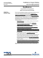
OxyBalance
Oxygen Display and Averaging System
READ THIS PAGE BEFORE PROCEEDING!
ESSENTIAL
INSTRUCTIONS
Emerson process Management designs, manufactures and tests its products
to meet many national and international standards. Because these
instruments are sophisticated technical products, you MUST properly
install, use, and maintain them to ensure they continue to operate within
their normal specifications. The following instructions MUST be adhered to
and integrated into your safety program when installing, using, and
maintaining Rosemount Analytical products. Failure to follow the proper
instructions may cause any one of the following situations to occur: Loss of
life; personal injury; property damage; damage to this instrument; and
warranty invalidation.
• Read all instructions
prior to installing, operating, and servicing the
product.
• If you do not understand any of the instructions, contact your
Rosemount Analytical representative for clarification.
• Follow all warnings, cautions, and instructions
marked on and
supplied with the product.
• Inform and educate your personnel in the proper installation,
operation, and maintenance of the product.
• Install your equipment as specified in the Installation Instructions
of the appropriate Instruction Manual and per applicable local and
national codes. Connect all products to the proper electrical and
pressure sources.
• To ensure proper performance, use qualified personnel
to install,
operate, update, program, and maintain the product.
• When replacement parts are required, ensure that qualified people use
replacement parts specified by Rosemount Analytical. Unauthorized
parts and procedures can affect the product's performance, place the
safe operation of your process at risk, and VOID YOUR WARRANTY.
Look-alike substitutions may result in fire, electrical hazards, or
improper operation.
• Ensure that all equipment doors are closed and protective covers
are in place, except when maintenance is being performed by
qualified persons, to prevent electrical shock and personal injury.
The information contained in this document is subject to change without
notice.

ii
Instruction Manual
IM-106-4050 Original Issue
March 2006
OxyBalance Oxygen Display
and Averaging System
PREFACE The purpose of this manual is to provide information concerning the
components, functions, installation and maintenance of the OxyBalance
Oxygen Display and Average System.
Some sections may describe equipment not used in your configuration. The
user should become thoroughly familiar with the operation of this module
before operating it. Read this instruction manual completely.
DEFINITIONS The following definitions apply to WARNINGS, CAUTIONS, and NOTES
found throughout this publication.
NOTE
Highlights an essential operating procedure, condition, or statement.
SYMBOLS
NOTE TO USERS
The number in the lower right corner of each illustration in this publication is a
manual illustration number. It is not a part number, and is not related to the
illustration in any technical manner.
If a Model 275/375 Universal HART® Communicator is used with this unit, the software
within the Model 275/375 may require modification. If a software modification is required,
please contact your local Emerson process Management Service Group or National
Response Center at 1-800-433-6076 or 1-888-433-6829.
Highlights an operation or maintenance procedure, practice, condition, statement, etc. If not
strictly observed, could result in injury, death, or long-term health hazards of personnel.
Highlights an operation or maintenance procedure, practice, condition, statement, etc. If not
strictly observed, could result in damage to or destruction of equipment, or loss of
effectiveness.
RISK OF ELECTRICAL SHOCK
WARNING: REFER TO INSTRUCTION MANUAL
PROTECTIVE CONDUCT OR TERMINAL
EARTH (GROUND) TERMINAL
:
:
:
:

Instruction Manual
IM-106-4050 Original Issue
March 2006
OxyBalance Oxygen Display
and Averaging System
http://www.processanalytic.com
Section 1 Description
Component Checklist . . . . . . . . . . . . . . . . . . . . . . . . . . . . . page 1-1
Part Numbers . . . . . . . . . . . . . . . . . . . . . . . . . . . . . . . . . . . page 1-1
System Overview . . . . . . . . . . . . . . . . . . . . . . . . . . . . . . . . page 1-2
Specifications . . . . . . . . . . . . . . . . . . . . . . . . . . . . . . . . . . . page 1-5
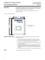
COMPONENT
CHECKLIST
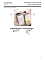
A typical Rosemount Analytical OxyBalance Oxygen Display and Averaging
System package should contain the items shown in Figure 1-1.
PART NUMBERS Use the part numbers listed in Table 1-1 to verify your OxyBalance system
part number. Copy the part number and serial number from the
OxyBalanceunit into the chart on the back cover of this manual. Refer tothis
complete part number for any correspondence with Emerson Process
Management.
Table 1-1. OxyBalance System
Part Numbers
Figure 1-1. Typical System
Package
1. Instruction Manual
2. OxyBalance Oxygen Display and Averaging System
Part Number Description
6A00203G01 1-4 probes, NEMA 4X enclosure
6A00203G02 5-8 probes, NEMA 4X enclosure
6A00203G03 1-4 probes, plate mounted
6A00203G04 5-8 probes, plate mounted
1
38370006
2
Analytical
A
n
a
l
y
t
i
c
a
l
OXYMITTER 4000
H
A
Z
A
R
D
O
U
S
A
R
E
A
O
X
Y
G
E
N
T
R
A
N
S
M
IT
T
E
R
Ins
tru
ction
Man
ual
IM
-10
6-34
0C
R
ev
.4.2
D
ecem
b
er2005

1-2
Instruction Manual
IM-106-4050 Original Issue
March 2006
OxyBalance Oxygen Display
and Averaging System
SYSTEM OVERVIEW
General The OxyBalance is a display and averaging system that augments the
Oxymitter O
2
probe product line. It receives up to (8) 4-20 mA signals from
Rosemount, Westinghouse, or other O
2
probes, and calculates and transmits
up to 4 additional programmable averages (again 4-20 mA). The OxyBalance
system also displays the individual and averaged outputs on a color touch
screen graphic panel. Trend screens, bar graphs (individual probes only), and
alarming indications are provided when a probe goes off line.
The OxyBalance system replaces much of the functionality of older averaging
systems offered by Westinghouse and Rosemount - the Control Room
Electronics (CRE), 1500 Controller-based averaging systems, and the
Veritrak-based 1290 systems. It should be noted, however, that the heater
control and signal conditioning for each individual probe is executed within
separate electronics for each probe. Unlike past averaging systems, and most
current competitive averaging systems, there is no component failure in the
OxyBalance system that will cause the loss of individual probe signals.
The OxyBalance system senses 4-20 mA inputs automatically. Averages are
very easy to set up. Any probes that may fail will default to a 3.5 mA signal
level, indicate in red, and the OxyBalance system will remove these probes
from the average. Likewise, probes that are in calibration will indicate blue,
and provide a contact closure to the OxyBalance system to remove them from
the average while calibrating.
Trends offer adjustable scaling, three time spans (5 min., 8 hrs., and 24 hrs.),
and panning capability back and forth in history.
OxyBalance System
Features
The standard OxyBalance system includes the following features:
• Graphically displays and trends from 1 to 8 O
2
measurements.
• Probe inputs may be from Rosemount Analytical, Westinghouse or any
competitive O
2
probe with a 4-20 mA signal output.
• Generates up to four 4-20 mA signals as programmable averages.
• Failed or calibrating probes are automatically removed from the
average
• Individual probe readings remain autonomous and are unaffected by
any potential failure of the OxyBalance system.
• Variable time scale trends for each individual probe value, as well as for
up to 4 averages.
• Password protection for set up menus.

Instruction Manual
IM-106-4050 Original Issue
March 2006
1-3
OxyBalance Oxygen Display
and Averaging System
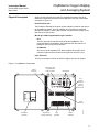
Physical Description Aside from the PanelView Plus 600, the OxyBalance system consists of
iadditional components mounted on three DIN rails. The main components
are shown in Figure 1-2.
PanelView Plus 600
The PanelView Plus 600 is the touch screen interface located on the front of
the OxyBalance system, all probe readings and averages are displayed
through this interface. There is also a power cord and communications cord
that connect to this module.
MicroLogix 1200 Programmable Logic Controller
PLC
The PLC process the raw data received by the OxyBalance. The
processed data is transmitted to the PanelView Plus 600, where it is
displayed on the touch screen interface.
I/O Modules
Also known as the expansion I/O, these modules act as part of the
controller system and are located on the right side of the PLC unit.
Input Terminals
This row of terminals receives the 4-20 mA signals from the O
2
probes.
Figure 1-2. OxyBalance Components
DCOMM
COMM0
FORCE
FAULT
RUN
POWER
OUT
47
IN
0123 5689
47
0 1 2 3 5 6 8 9 10 11 12 13
1
0
4
3
2
0
1
0
1
3
4
3
4
22
7
6
5
5
6
7
5
6
7
38370016
PanelView
Plus 600
MicroLogix 1200
Programmable
Logic Controller
I/O Modules
Input
Terminals
Output
Terminals
Signal Pass
Through Terminals
Failure/
Warning
Terminals
Power
Terminals
In Cal
Terminals
PLC
Failure
Terminals

1-4
Instruction Manual
IM-106-4050 Original Issue
March 2006
OxyBalance Oxygen Display
and Averaging System
Signal Pass Through Terminals
The pass through terminals are located on the input terminals. These
terminals provide connection points for passing on the incoming O
2
signal to
other devices.
Output (Average) Terminals
These terminals provide a connection point for the average O
2
% 4-20 mA
signals.
Failure / Warning Terminals
These terminals provide connection points for the output signal warning and
failure contacts.
In Cal Terminals
These terminals provide connection points for In Cal signals from the
individual oxygen probes. When a probe is in calibration, it is removed from
any average calculations.
Power Terminals
This terminal provides wire contacts for power distribution in the OxyBalance
system.
OxyBalance operating specifications are listed in Table 1-2.

Instruction Manual
IM-106-4050 Original Issue
March 2006
1-5
OxyBalance Oxygen Display
and Averaging System
SPECIFICATIONS Specifications for the OxyBalance system are listied in Table 1-2.
Table 1-2. OxyBalance Specifications
(1)
Specifications are subject to change without notification. Our policy is one of continuous
improvement and we reserve the right to change specifications.
(2)
1.5A above 40
o
C.
SPECIFICATIONS
(1)
Ambient Environment
Temperature specification 23
o
F to 149
o
F (-5
o
C to 65
o
C)
Ambient temperature effect on electronics Less than .01% of reading per 10
o
C
Vibration IEC 68-2-6 and ISA S37.3
Shock IEC 68-2-31 and ISA S37.3
Enclosure NEMA 4X
Area Classification General Purpose
Power Requirements 100-240 VAC, 50/60 Hz
MicroLogix 1200
Resistive Load on Current Output 0 to 500 Ohms (includes wire resistance)
Input Impedance for Current Terminal 275 Ohms
PanelView Plus 600
Minimum On-State Current 2.0 mA at 10V dc
Nominal On-State Current 8.9 mA at 24V dc
Maximum On-State Current 12. mA at 30V dc
Current per Group Common 8A
240V ac (Maximum Volts) 2.5A
(2)
(Amperes Continuous)
120V ac (Maximum Volts) 2.5A
(2)
(Amperes Continuous)
125V dc (Maximum Volts) 1.0A (Amperes Continuous)
24V dc (Maximum Volts) 2.0A (Amperes Continuous)
I/O
Signal Inputs 4-20 mA (qty. 1 to 8 O
2
probes)
Signal Outputs 4-20 mA (qty, 1 to 8 pass through each probe, qty. 4 programmable averages)
Signal Output Resolution (for averages) 12 bit
Signal Output Resistive Load Less than 500 ohms
Discrete Inputs "IN CAL" (qty. 2 to 8 from individual probes)
Relay Outputs
"LOSS OF PLC"
"AVERAGE WARN" if one or more probes drop out of an average.
"AVERAGE FAILED" for each average when only one probe in the average
remains valid.
Architecture
Each probe utilizes its own autonomous conditioning electronics, including its
own power supply. Any failure in the OxyBalance system will not affect the
individual 4-20 mA signals going to the control room for each probe.
Logic 4 programmable averages from 2-8 probes
Individual probes removed from average if
1.) Probe fails (4-20 mA to default condition of 3.5 mA or 21 mA
2.) Probe is in cal (SPS / IMPS contact, must share with control room)
Signal Security
4-20 mA signals to be wired in series to the PLC and to the DCS I/O marshalling
panel such that the loss of the PLC will not affect the transmission of the
individual probe signals to the DCS. If PLC power, I/O cards or processor card(s)
are lost, 4-20 mA signals from the probes are still transmitted to the control room.
Personnel Security Password protection configuration changes in programmable averages.
Color Graphic Display
Size 6" diagonal
Type Color Active Matrix, TFT LCD
Resolution 320 by 240 min. Touch screen operator interface

1-6
Instruction Manual
IM-106-4050 Original Issue
March 2006
OxyBalance Oxygen Display
and Averaging System

Instruction Manual
IM-106-4050 Original Issue
March 2006
OxyBalance Oxygen Display
and Averaging System
http://www.processanalytic.com
Section 2 Installation
Overview . . . . . . . . . . . . . . . . . . . . . . . . . . . . . . . . . . . . . . . page 2-1
System Considerations . . . . . . . . . . . . . . . . . . . . . . . . . . . page 2-1
Mounting . . . . . . . . . . . . . . . . . . . . . . . . . . . . . . . . . . . . . . . page 2-2
Wiring Connections . . . . . . . . . . . . . . . . . . . . . . . . . . . . . . page 2-2
Setup . . . . . . . . . . . . . . . . . . . . . . . . . . . . . . . . . . . . . . . . . . page 2-2
OVERVIEW This section describes:
1. Wall-mounting of the OxyBalance system.
2. The necessary wiring schematics for proper connection of the
OxyBalance system.
3. Setup procedures conducted through the PanelView Plus 600 on how to
configure, assign nomenclature, change/update display settings, and
assigning the O
2
probes to the average outputs.
SYSTEM
CONSIDERATIONS
Prior to installation of the OxyBalance system, check for all components
necessary to install the system completely. When selecting a mounting
location, determine where the OxyBalance system will be placed in terms of
serviceability, ambient temperatures, environmental considerations, and
convenience.
Before starting to install this equipment, read the "Safety Instructions" in Appendix A: Safety
Data. Failure to follow the safety instructions could result in serious injury or death.
Disconnect all power before installing or replacing components. Failure to disconnect power
may result in electrical shock and/or damage to the terminal.
Install all protective equipment covers and safety ground leads after installation. Failure to
secure covers and ground leads could result in serious injury or death.

2-2
Instruction Manual
IM-106-4050 Original Issue
March 2006
OxyBalance Oxygen Display
and Averaging System
MOUNTING The OxyBalance Oxygen Display and Averaging System was designed to be
wall-mounted or simply placed on a table. Locate the unit where the ambient
temperature is between 23
o
F to 149
o
F (-5
o
C to 65
o
C).
The outline drawing in Figure 2-1 shows mounting dimensions of the
OxyBalance system.
Figure 2-1. Mounting Dimensions
WIRING CONNECTIONS Refer to Figure 2-2 and connect the input and output signal wiring to the
OxyBalance as follows:
1. Connect the incoming 4-20mA signals to the input signal terminals.
2. Connect the 4-20mA average O
2
signals to the output signal terminals.
3. Connect the In Cal input signals to the in cal signal terminals.
4. Connect the warning and failure signal output wiring to the warning and
failure signal terminals.
5. If the signal pass-through feature for the incoming O
2
signals will be
used, remove the jumpers from the pass-through terminals. Connect the
outgoing O
2
signal wires to the raised output signal terminals. Refer to
Figure 2-3.
6. Connect 90-240Vac, 50/60 Hz input power to the power input terminals.
SETUP For setup information, refer to Section 3, Setup.
12.00
(304,8)
17.12
(434,8)
Note: All dimensions are
in inches with millimeters
in parentheses.
38370002

2-3
Instruction Manual
IM-106-4050 Original Issue
March 2006
OxyBalance Oxygen Display
and Averaging System
Figure 2-2. Installation Wiring Schematic
DCOMM
COMM0
FORCE
FAULT
RUN
POWER
OUT
47
IN
0123 5689
47
0 1 2 3 5 6 8 9 10 11 12 13
1
0
4
3
2
0
1
0
1
3
4
3
4
22
7
6
5
5
6
7
5
6
7
38370003
Average 4-20 mA
Output Signals
Probe 1
Probe 2
Probe 3
Probe 4
Probe 5
Probe 6
Probe 7
Probe 8
Average 1
Average 2
Average 3
Average 4
Incoming 4-20 mA
O Signals
2
+
-
+
-
+
-
+
-
+
-
+
-
+
-
+
-
+
-
+
-
+
-
+
-
Line
Voltage
Line
Neutral
Ground
Probe 1
In Cal
Contacts
Probe 2
Probe 3
Probe 4
Probe 5
Probe 6
Probe 7
Probe 8
PLC Failure
Avg 1&2 Fail Common
Avg 1 Fail
Avg 2 Fail
Avg 3&4 Fail Common
Avg 3 Fail
Avg 4 Fail
Avg Warning Common
Avg 1 Warning
Avg 2 Warning
Avg 3 Warning
Avg 4 Warning

2-4
Instruction Manual
IM-106-4050 Original Issue
March 2006
OxyBalance Oxygen Display
and Averaging System
Figure 2-3. Pass-Through Terminals
DCOMM
COMM0
FORCE
FAULT
RUN
POWER
OUT
47
IN
012356 89
47
012356 8910111213
1
0
4
3
2
0
1
0
1
3
4
3
4
22
7
6
5
5
6
7
5
6
7
38370015
4-20 mA
Pass-Through
Terminals
4-20 mA
Input
Terminals

Instruction Manual
IM-106-4050 Original Issue
March 2006
OxyBalance Oxygen Display
and Averaging System
http://www.processanalytic.com
Section 3 Setup
Overview . . . . . . . . . . . . . . . . . . . . . . . . . . . . . . . . . . . . . . . page 3-1
Setup . . . . . . . . . . . . . . . . . . . . . . . . . . . . . . . . . . . . . . . . . . page 3-1
OVERVIEW This section provides information on setup and configuration of the
OxyBalance Oxygen Display and Averaging System
SETUP Each O
2
probe generates a 4-20 mA output signal that is received by the
OxyBalance system. When a probe channel detects a current signal greater
than 3.5 mA, that probe is considered active, and is automatically made
available. It is not necessary to tell the OxyBalance that a probe is present. It
is automatically detected and used. Table 3-1 shows how the OxyBalance
system interprets and displays these signals.
Table 3-1. Signal Interpretation
After these signals are converted into an O
2
% they are displayed on the
touch screen interface. The rest of this section will outline the necessary steps
to configure and operate the OxyBalance system through the touch screen
interface.
Before starting to install this equipment, read the "Safety Instructions" in Appendix A: Safety
Data. Failure to follow the safety instructions could result in serious injury or death.
Disconnect all power before installing or replacing components. Failure to disconnect power
may result in electrical shock and/or damage to the equipment.
4-20 mA Signal Value Status Display Color
<3.5 mA Probe Inactive Not Shown
3.5 mA to 3.6 mA
Probe Failed
Red
3.6 mA to 3.8 mA Reading Under Range Yellow
3.8 mA to 20.5 mA Good Reading Green
20.5 mA to 21 mA Reading Over Range Yellow
>21 mA Probe Failed Red

3-2
Instruction Manual
IM-106-4050 Original Issue
March 2006
OxyBalance Oxygen Display
and Averaging System
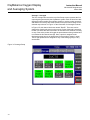
All of the operations that are conducted through the touch screen interface,
are conducted through five subject tabs that appear on the right hand side of
the interface.
• Current
•Trend
•Login
• Setup
•Alarm
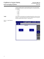
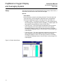
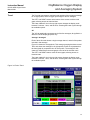
Login The operation of the interface can be password protected, so either the Login
Required, or Login Not Required screen will be displayed once the Login tab
has been pressed, Refer to Figure 3-1 and Figure 3-2.
Figure 3-1. Login Required
Screen

Instruction Manual
IM-106-4050 Original Issue
March 2006
3-3
OxyBalance Oxygen Display
and Averaging System
Figure 3-2. Login Not
Required Screen

3-4
Instruction Manual
IM-106-4050 Original Issue
March 2006
OxyBalance Oxygen Display
and Averaging System
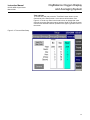
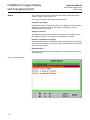
Setup The Setup tab continas five sub-tabs displayed along the top of the screen; a
General tab, and one tab for each of the four averages.
General
Scale Values
Under this tab the values for the Analog full scale, Trend min value and
Trend max value, can be changed to represent more of an applicable
scale when displaying the probe or average outputs. See Figure 3-3.
• Analog full scale - This setting controls the O
2
% value represented by
the incoming 4-20 mA signals, and the average O
2
% output signals. All
input signals must represent the same full scale value.
• Trend min value - This values allows the adjustment of the minimum
value displayed on the trend graphs on the touch screen display,
allowing the display to zoom in on the range of interest. This setting
only affects the displayed values. It has no affect on the average O
2
%
output signals.
• Trend max value - This values allows the adjustment of the maximum
value displayed on the trend graphs on the touch screen display,
allowing the display to zoom in on the range of interest. This setting
only affects the displayed values. It has no affect on the average O
2
%
output signals.
Figure 3-3. Scale Values Setup

Instruction Manual
IM-106-4050 Original Issue
March 2006
3-5
OxyBalance Oxygen Display
and Averaging System
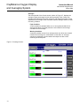
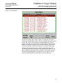
Time and Date
To set the time and date press the "Time/Date" button shown on the
General tab of the Setup screen. A new screen will be shown. See
Figure 3-4. Touch any value in the Actual column to change that value.
Once the new value has been entered, hold the "Hold To Set Clock" button
until the time and date has been updated in the upper right hand corner of
the screen.
Figure 3-4. Time and Date Setup
Page is loading ...
Page is loading ...
Page is loading ...
Page is loading ...
Page is loading ...
Page is loading ...
Page is loading ...
Page is loading ...
Page is loading ...
Page is loading ...
Page is loading ...
Page is loading ...
Page is loading ...
Page is loading ...
Page is loading ...
Page is loading ...
Page is loading ...
Page is loading ...
Page is loading ...
Page is loading ...
Page is loading ...
Page is loading ...
Page is loading ...
Page is loading ...
Page is loading ...
Page is loading ...
Page is loading ...
Page is loading ...
Page is loading ...
Page is loading ...
Page is loading ...
Page is loading ...
Page is loading ...
Page is loading ...
Page is loading ...
Page is loading ...
Page is loading ...
Page is loading ...
Page is loading ...
Page is loading ...
Page is loading ...
Page is loading ...
Page is loading ...
-
 1
1
-
 2
2
-
 3
3
-
 4
4
-
 5
5
-
 6
6
-
 7
7
-
 8
8
-
 9
9
-
 10
10
-
 11
11
-
 12
12
-
 13
13
-
 14
14
-
 15
15
-
 16
16
-
 17
17
-
 18
18
-
 19
19
-
 20
20
-
 21
21
-
 22
22
-
 23
23
-
 24
24
-
 25
25
-
 26
26
-
 27
27
-
 28
28
-
 29
29
-
 30
30
-
 31
31
-
 32
32
-
 33
33
-
 34
34
-
 35
35
-
 36
36
-
 37
37
-
 38
38
-
 39
39
-
 40
40
-
 41
41
-
 42
42
-
 43
43
-
 44
44
-
 45
45
-
 46
46
-
 47
47
-
 48
48
-
 49
49
-
 50
50
-
 51
51
-
 52
52
-
 53
53
-
 54
54
-
 55
55
-
 56
56
-
 57
57
-
 58
58
-
 59
59
-
 60
60
-
 61
61
-
 62
62
-
 63
63
-
 64
64


Emerson OxyBalance User manual
- Category
- Oxygen Equipment
- Type
- User manual
- This manual is also suitable for
Ask a question and I''ll find the answer in the document
Finding information in a document is now easier with AI
Related papers
-
Rosemount 5081FG User manual
-
Emerson 4000 User manual
-
Emerson Process Management Oxymitter 4000 User manual
-
-
Rosemount MicroCEM-Rev A User manual
-
-
-
-
-
Other documents
-
-
-
-
-
-
-
-
-
-