
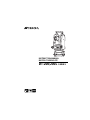
DT-200/200L
SERIES
INSTRUCTION MANUAL
DIGITAL THEODOLITE


1
FOREWORD
Thank you for purchasing the TOPCON Digital Theodolite. For the best per-
formance of the instruments, please carefully read these instructions and
keep them in a convenient location for future reference.

2
General Handling Precautions
Before starting work or operation, be sure to check that the instrument is
functioning correctly with normal performance.
Do not submerge the instrument into water.
The instrument can not be submerged underwater.
The instrument is designed based on the International Standard IP66,
therefore it is protected from the normal rainfall.
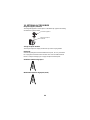
Setting the instrument on a tripod
When mounting the instrument on a tripod, use a wooden tripod when possi-
ble. The vibrations that may occur when using a metallic tripod can effect the
measuring precision.
Installing the tribrach
If the tribrach is installed incorrectly, the measuring precision could be
effected. Occasionally check the adjusting screws on the tribrach. Make sure
the base fixing lever is locked and the base fixing screws are tightened.
Guarding the instrument against shocks
When transporting the instrument, provide some protection to minimize risk
of shocks. Heavy shocks may cause the measurement to be faulty.
Carrying the instrument
Always carry the instrument by its handgrip.
Exposing the instrument to extreme heat.
Do not leave the instrument in extreme heat for longer than necessary.
It could adversely affect its performance.
Sudden changes of temperature
Any sudden change of temperature to the instrument or prism may result in a
reduction of measuring distance range, i.e when taking the instrument out
from a heated vehicle. Let instrument acclimate itself to ambient tempera-
ture. When a high degree of precision is required for measurement, provide
shade against direct sunlight for the instrument and tripod.
Battery level check
Confirm battery level remaining before operating.
Store with the batteries removed, when operation is halted for more than a
month. Leaving the batteries attached for extended period of time can result
in battery leakage, which may lead to malfunctioning.

3
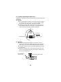
Notice on Transceiver
When using high output transceiver etc., make sure it does not come near
the instrument.
Opening the carrying case
When opening the carrying case and taking out the instrument, place the
case horizontally, then open the case.

4
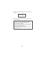
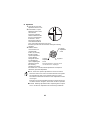
Display for Safe Use
In order to encourage the safe use of products and prevent any danger to the
operator and others or damage to properties, important warnings are put on
the products and inserted in the instruction manuals.
We suggest that everyone understand the meaning of the following displays
and icons before reading the “Safety Cautions” and text
● Injury refers to hurt, burn, electric shock, etc.
● Physical damage refers to extensive damage to buildings or equipment and
furniture.
Safety Cautions
Display Meaning
Ignoring or disregard of this display may lead to the
danger of death or serious injury.
Ignoring or disregard of this display may lead to per-
sonal injury or physical damage.
WARNING
•There is a risk of fire, electric shock or physical harm if you attempt
to disassemble or repair the instrument yourself.
This is only to be carried out by TOPCON or an authorized dealer,
only!
•Laser beams can be dangerous, and can cause eye injury's if used
incorrectly.
Never attempt to repair the instrument yourself.
•Cause eye injury or blindness.
Do not stare into beam.
•Cause eye injury or blindness.
Do not look at the sun through a telescope.
•High temperature may cause fire.
Do not connect the battery to an instrument while it is charging.
•Risk of fire or electric shock.
Do not use a wet battery or charger.
•May ignite explosively.
Never use an instrument near flammable gas, liquid matter, and do
not use in a coal mine.
WARNING
CAUTION

5
•Battery can cause explosion or injury.
Do not dispose in fire or heat.
•Risk of fire or electric shock.
Do not use any power voltage except the one given on manufactur-
ers instructions.
•Battery can cause outbreak of fire.
Do not block up the vent of the battery.
•The short circuit of a battery can cause a fire.
Do not short circuit battery when storing it.
CAUTION
Use of controls or adjustment or performance of procedures other
than those specified herein may result in hazardous radiation expo-
sure.
Do not connect or disconnect equipment with wet hands, you are at
risk of electric shocks if you do!
Risk of injury by overturn the carrying case.
Do not stand or sit on the carrying cases.
Please note that the tips of tripod can be hazardous, be aware of this
when setting up or carrying the tripod.
Risk of injury by falling down the instrument or case.
Do not use a carrying case with a damaged which belts, grips or
latches.
Do not allow skin or clothing to come into contact with acid from the
batteries, if this does occur then wash off with copious amounts of
water and seek medical advice.
A plumb bob can cause an injury to a person if used incorrectly.
It could be dangerous if the instrument falls over, please ensure you
attach a handle to the instrument securely.
Ensure that you mount the Tribrach correctly, failing to do so may re-
sult in injury if the tribrach were to fall over.
It could be dangerous if the instrument falls over, please check that
you fix the instrument to the tripod correctly.
Risk of injury by falling down a tripod and an instrument.
Always check that the screws of tripod are tightened.

6
Laser Safety
DT-205L/207L/209L uses the visible laser beam. DT-205L/207L/209L prod-
ucts are manufactured and sold in accordance with “Radiation Safety of
Laser Products, Equipment Classification, Requirements and User‘s Guide”
(IEC Publication 60825-1) or “Performance Standards for Light-Emitting
Products” (FDA/BRH 21 CFR 1040) provided on the safety standards for
laser beam.
As per the said standards, DT-205L/207L/209L classified as “Class 2
(CLASS II) Laser Products”.
The laser beam belongs not very dangerous type but we request you to keep
and understand “Safety standard for users” as mentioned in the manual
instruction.
In case of any failure, do not disassemble the instrument. Contact TOPCON
or your TOPCON dealer.
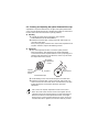
Labels
Find the labels which describes the caution and safety about the laser beam
as follows in DT-205L/207L/209L. We request you to replace it one anytime
the caution labels are damaged or lost and paste a new one at the same
place. You can get the labels from Topcon or your dealer.
CLASSII LASER PRODUCTDIODE LASER
WAVE LENGTH 633nm
0.6mW MAXIMUM OUTPUT
CAUTION
LASER RADIATION
DO NOT STARE INTO BEAM
AVOID EXPOSUR
E
LASER LIGHT IS EMITTED
FROM THIS APERTURE
CLASS 3A @LASER PRODUCT
DO NOT STARE INTO THE BEAM OF VIEW
LASER RADIATION
DIRECTLY WITH OPTICAL INSTRUMENTS
Beam aperture
Depending on the country where the instrument is sold,
either of these labels may be found on the instrument.

7
User
1) This product is for professional use only!
The user is required to be a qualified surveyor or have a good knowledge
of surveying, in order to understand the user and safety instructions,
before operating, inspecting or adjusting.
2) Wear the required protectors (safety shoes, helmet, etc.) when operating.
Exceptions from Responsibility
1) The user of this product is expected to follow all operating instructions
and make periodic checks of the product’s performance.
2) The manufacturer, or its representatives, assumes no responsibility for
results of a faulty or intentional usage or misuse including any direct,
indirect, consequential damage, and loss of profits.
3) The manufacturer, or its representatives, assumes no responsibility for
consequential damage, and loss of profits by any disaster, (an earth-
quake, storms, floods etc.).
A fire, accident, or an act of a third party and/or a usage any other usual
conditions.
4) The manufacturer, or its representatives, assumes no responsibility for
any damage, and loss of profits due to a change of data, loss of data, an
interruption of business etc., caused by using the product or an unusable
product.
5) The manufacturer, or its representatives, assumes no responsibility for
any damage, and loss of profits caused by usage except for explained in
the user manual.
6) The manufacturer, or its representatives, assumes no responsibility for
damage caused by wrong movement, or action due to connecting with
other products.

8
Contents
FOREWORD ........................................................................................................ 1
General Handling Precautions ...................................................................2
Display for Safe Use ..................................................................................4
Safety Cautions .........................................................................................4
Laser Safety ...............................................................................................6
User ...........................................................................................................7
Exceptions from Responsibility ..................................................................7
Contents ....................................................................................................8
Standard Set Composition .........................................................................9
1 NOMENCLATURE AND FUNCTIONS .................................................... 10
1.1 Nomenclature.................................................................................... 10
1.2 Display............................................................................................... 14
1.3 Operating keys.................................................................................. 14
2 PREPARATION FOR MEASUREMENT.................................................. 16
2.1 Setting Instrument Up for Measurement ........................................... 16
2.2 Power Switch Key ON....................................................................... 18
2.3 Battery Level Indicator....................................................................... 19
2.4 Vertical Angle Tilt Correction............................................................. 19
2.5 Serial Signal RS-232C Connector..................................................... 19
3 MEASUREMENT...................................................................................... 20
3.1 Measuring Horizontal Angle Right and Vertical Angle....................... 20
3.2 Switching Horizontal Angle Right / Left ............................................. 21
3.3 Measuring from the Required Horizontal Angle................................ 22
3.4 Vertical Angle % display.................................................................... 22
3.5 Repetition Angle Measurement......................................................... 23
3.6 Stadia Surveying ............................................................................... 25
4 HOW TO OPERATE THE LASER........................................................... 26
5 THE OTHER FUNCTIONS....................................................................... 27
5.1 Buzzer Sounding for Horizontal Angle 90° Increments..................... 27
5.2 Compasses (vertical angle)............................................................... 27
5.3 Auto Cut Off....................................................................................... 27
5.4 Setting Minimum Angle Reading....................................................... 27
5.5 Detach / Attach of Tribrach................................................................ 28
6 SELECTING MODE ................................................................................. 29
6.1 Items of the Selecting Mode.............................................................. 29
6.2 How to Set the Selecting Modes ....................................................... 31
7 HANDLING POWER SOURCE................................................................ 34
7.1 For removing..................................................................................... 34
7.2 Replace the battery (DB-35).............................................................. 34
7.3 For installing...................................................................................... 34
8 CHECK AND ADJUSTMENT................................................................... 35
8.1 Checking /Adjusting the Plate Level.................................................. 36
8.2 Checking and Adjusting the Circular Level........................................ 37
8.3 Adjustment of the Vertical Cross-hair................................................ 38
8.4 Collimation of the Instrument............................................................. 40
8.5 Checking and Adjusting the Optical Plummet Telescope.................. 42
8.6 Adjustment of Vertical Angle 0 Datum............................................... 43
8.7 Adjustment of Laser Beam................................................................ 44
9 STORAGE PRECAUTIONS..................................................................... 45
10 OPTIONAL ACCESSORIES.................................................................... 46
11 ERROR DISPLAY.................................................................................... 47
12 SPECIFICATIONS.................................................................................... 48

9
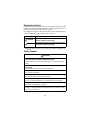
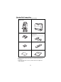
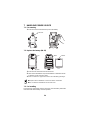
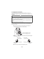
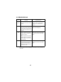
Standard Set Composition
The numerical value in parentheses shows the quantity.
• Make sure that all of the above items are with the instrument when
purchased.
• Guarantee card, Laser use card, Caution sticker are supplied for
certain markets.
Instrument
(1)
(
with lens cap
)
Carrying case
(1)
Plumb bob set
(1)
Tool kit
(1)
Cleaning brush, Screw driver, Rod pins,
Plumb bob hook
(Hexagonal wrench : Only for DT-205/207/209/209P)
AA batteries (4) Plastic rain cover (1)
Silicon cloth
(1)
Instruction manual (1)

10
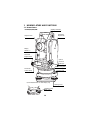
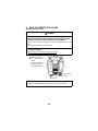
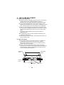
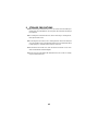
1 NOMENCLATURE AND FUNCTIONS
1.1 Nomenclature
Circular level
Display
window *1)
Objective lens
Sighting collimator
Optical
plummet
telescope
Horizontal
tangent screw
Horizontal
motion clamp
*1) DT-209/209P has one side display only.
Leveling screw
Instrument
height mark
DT-205/207/209/209P
Centering screw
(209P only)
Tribrach fixing leve
r
(205/207 only)

11
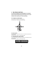
RS-232C Connector
(205 only)
Operation keys
Plate leve
l
Battery
Cross-hair adjustmen
t
section cover
Telescope
focusing knob
Handle
Telescope eyepiece
Vertical tangen
t
screw
Vertical motion
clamp
Handle fixing knob
Plate level
(207 only)
Base
Tribrach type
DT-205/207: Detachable
DT-209: Fixing
DT-209P: Centering

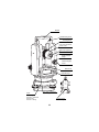
12
Circular level
Display
window *1)
Objective lens
Sighting collimator
Optical
plummet
telescope
Horizontal
tangent screw
Horizontal
motion clamp
Leveling screw
Instrument
height mark
*1) DT-209L has one side display only.
Tribrach fixing lever
DT-205L/207L/209L
(205L/207L only)

13
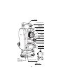
Plate level
(207L only)
Operation keys
Laser axis adjusting
screw (with cap)
Vertical tangent
screw
Vertical motion
clamp
Plate level
Battery
Cross-hair adjustment
section cover
Telescope
focusing knob
Handle
Telescope eyepiece
Handle fixing knob
Base
RS-232C Connector
(205L only)
Tribrach type
DT-205L/207L: Detachable
DT-209L: Fixing

14
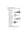
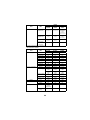
1.2 Display
Display marks
1.3 Operating keys
Display Contents Display Contents
V
Vertical angle
TILT
Tilt correction mode
(DT-205/205L only)
HR
Horizontal angle right
F
Function key selection
mode
HL
Horizontal angle left
%
Percent grade
Ht
Repetition angle mea-
surement
G
Unit display GON
8AVG
The number of repeti-
tion / Average of angle
Key Function Key Function (Function mode)
Power switch
REP
Repetition angle mea-
surement
R/L
Selection for horizontal an-
gle right / left measurement
Illumination of display
ON/OFF
V/%
Vertical angle display
Selection for vertical angle /
percent display
Moving the blinking digit
to the left
HOLD
Holding the horizontal angle
Moving the blinking the
digit to the right
0 SET
Horizontal angle 0° set
Increment the blinking
numeral
FUNC
Upper function selection
Function mode

15
Adjustment mode and Selecting mode
Mode Key
Adjustment mode of vertical angle 0
datum
Turn the power ON while pressing
the [0 SET] key.
Selecting mode 1
Turn the power ON while pressing
the [R/L] key.
Selecting mode 2
Turn the power ON while pressing
the [V/%] key.

16
2 PREPARATION FOR MEASUREMENT
2.1 Setting Instrument Up for Measurement
Setting up the Tripod
First, extend the extension legs to suitable lengths and tighten the screws on
their midsections.
Attaching the Instrument on the Tripod Head
Place the instrument carefully on the tripod head and slide the instrument by
loosening the tripod screw. If the plumb bob is positioned right over the cen-
ter of the point, slightly tighten the tripod screw.
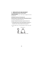
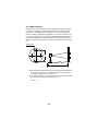
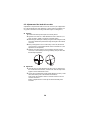
Roughly Leveling the Instrument by Using the Circular Level
1) Turn the leveling screws A and B to move the bubble in the circular level.
The bubble is now located on a line perpendicular to a line running
through the centers of the two leveling screws being adjusted.
2) Turn the leveling screw C to bring the bubble to the center of the circular
level.
Leveling screw C
Leveling screw A
Leveling screw B

17
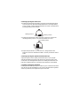
Centering by Using the Plate Level
1) Rotate the instrument horizontally by using the Horizontal motion/clamp
screw and place the plate level parallel with the line connecting leveling
screws A and B, and then bring the bubble to the center of the plate level
by turning leveling screws A and B.
2) Rotate the instrument 90° (100g) around its vertical axis and turn the
remaining leveling screw or C to center the bubble once more.
3) Repeat the procedures 1 and 2 for each 90° (100g) rotation of the
instrument and check whether the bubble is correctly centered for all four
points.
Centering by Using the Optical Plummet Telescope
Adjust the eyepiece of the optical plummet telescope to your eyesight.
Slide the instrument by loosening the tripod screw, place the point on the
center mark, and then tighten the tripod screw. Sliding the instrument care-
fully not to rotate that allows you to get the least dislocation of the bubble
Completely Leveling the Instrument
Leveling the instrument precisely in a similar way to 4. Rotate the instrument
and check to see that the bubble is in the center of the plate level regardless
of telescope direction, then tighten the tripod screw hard.
Leveling screw A
Leveling screw B
Leveling screw C

18
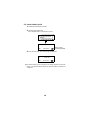
2.2 Power Switch Key ON
1
Confirm the instrument is leveled.
2
Turn the power switch ON.
Every segment turns on for about 1 second.
3
Press the [V/%] key. The vertical angle is displayed.
● Confirm the battery power remaining on the display. Replace with charged
battery or charge when battery level is low. Refer to Section 2.3 “Battery Lev-
el Indicator” .
Battery Power
Remaining Display
HR 342°03’41”
V 11°50’28”
HR 342°03’41”
Page is loading ...
Page is loading ...
Page is loading ...
Page is loading ...
Page is loading ...
Page is loading ...
Page is loading ...
Page is loading ...
Page is loading ...
Page is loading ...
Page is loading ...
Page is loading ...
Page is loading ...
Page is loading ...
Page is loading ...
Page is loading ...
Page is loading ...
Page is loading ...
Page is loading ...
Page is loading ...
Page is loading ...
Page is loading ...
Page is loading ...
Page is loading ...
Page is loading ...
Page is loading ...
Page is loading ...
Page is loading ...
Page is loading ...
Page is loading ...
Page is loading ...
Page is loading ...
Page is loading ...
-
 1
1
-
 2
2
-
 3
3
-
 4
4
-
 5
5
-
 6
6
-
 7
7
-
 8
8
-
 9
9
-
 10
10
-
 11
11
-
 12
12
-
 13
13
-
 14
14
-
 15
15
-
 16
16
-
 17
17
-
 18
18
-
 19
19
-
 20
20
-
 21
21
-
 22
22
-
 23
23
-
 24
24
-
 25
25
-
 26
26
-
 27
27
-
 28
28
-
 29
29
-
 30
30
-
 31
31
-
 32
32
-
 33
33
-
 34
34
-
 35
35
-
 36
36
-
 37
37
-
 38
38
-
 39
39
-
 40
40
-
 41
41
-
 42
42
-
 43
43
-
 44
44
-
 45
45
-
 46
46
-
 47
47
-
 48
48
-
 49
49
-
 50
50
-
 51
51
-
 52
52
-
 53
53


Ask a question and I''ll find the answer in the document
Finding information in a document is now easier with AI
Other documents
-
Sony SLV-N500 Installation guide
-
Elenco MX700K User manual
-
Sokkia iX Robotic Total Station User manual
-
Topcon Synergy GM-50 series User manual
-
-
AMX AXT-CV TiltScreen CATP User manual
-
-
-
ADA INSTRUMENTS А00571 Cube 360-2v Green Line Laser User manual
-