Craftsman 139536481DM Owner's manual
- Category
- Garage Door Opener
- Type
- Owner's manual

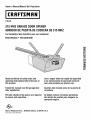
Owner's Manual/ManualDel Propietario
CRRFTSMRN °
1/2 HP
315 MHZGARAGEDOOROPENER
ABRIDORDEPUERTADECOCHERADE315 MHZ
ForResidentialUse0nly/S61oparausoresidencial
Model/Modelo• 139.536481DM
I"I'I
I""
Oo
I"t"l
Oo
"10
Z_
I""
Readandfollowall safetyrulesand
operatinginstructionsbeforefirstuseof
thisproduct.
Fastenthe manualnearthegaragedoor
after installation.
Leery seguirtodaslas reglasdeseguridad
y lasinstruccionesdeoperaci6n antesde
usaresteproductoporprimeravez.
Guardarestemanualcercade la puerta de
la cochera.
Periodic checksof theopener arerequ
to ensuresafeoperation.
ired
Sedebenrealizarrevisionesperi6dicas
delabridordepuertas paraasegurarsu
operaci6n segura.
oQ°s
Sears, Roebuck and Co., Hoffman Estates, IL 60179 U.S.A
www.sears.com/craftsman

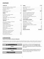
TABLE OF CONTENTS
Introduction 2-5
Safetysymbol and signal word review ..................... 2
Preparingyour garagedoor ............................. 3
Tools needed......................................... 3
Planning .......................................... 4-5
Carton inventory ...................................... 6
Hardware inventory.................................... 7
Assembly 8-11
Assemblethe rail and attachthe pulleybracket .............. 8
Install the trolley ...................................... 9
Attachthe rail to the motor unit .......................... 9
Install the chain/cableand the sprocket cover .............. 10
Tighten the chainand cable ............................ 11
Installation 11-26
Installation safety instructions .......................... 11
Determinethe headerbracket location .................... 12
Install the header bracket .............................. 13
Attachthe rail to the headerbracket ...................... 14
Position theopener................................... 15
Hangthe opener ..................................... 16
Install the door control ................................ 17
Install the light ...................................... 18
Attachthe emergency releaseropeand handle.............. 18
Electricalrequirements ................................ 19
Install the ProtectorSystem-_........................ 20-22
Fastenthe door bracket............................. 23-24
Connectthedoor arm to the trolley ................... 25-26
Adjustment 27-29
Adjust thetravel limits ................................ 27
Adjust theforce...................................... 28
Testthe safety reversal system.......................... 29
Testthe ProtectorSystem®............................. 29
Operation 30-34
Operationsafety instructions ........................... 30
Usingyour garagedoor opener ......................... 30
Usingthe wall-mounted door control ..................... 31
To open thedoor manually............................. 31
Careofyour garagedoor opener ........................ 32
Havinga problem? ................................... 33
Diagnosticchart ..................................... 34
Programming 35-36
To add or reprogram a hand-held remotecontrol............ 35
To eraseall codes.................................... 35
3-function remotes................................... 35
To add, reprogram or changea KeylessEntry PIN ........... 36
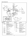
Repair Parts 37-38
Railassembly parts................................... 37
Installation parts ..................................... 37
Motor unit assembly parts ............................. 38
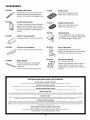
Accessories 39
Warranty
RepairPartsandService
39
Back Cover
INTRODUCTION
SafetySymbolandSignal WordReview
This garagedoor opener has beendesignedand testedto offer safe service providedit is installed, operated,maintained and testedin
strict accordancewith the instructions and warnings contained in this manual.
Mechanical
Electrical
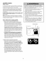
Whenyou seetheseSafetySymbols and Signal Words on the
following pages,they will alertyou to the possibility of serious
injury or deathif you do not comply with the warnings that
accompanythem. The hazardmay come from something
mechanicalor from electric shock. Readthe warnings carefully.
Whenyou seethis Signal Word on the following pages,it will alert
you to the possibility of damageto your garagedoor and/orthe
garagedoor opener ifyou do not comply with the cautionary
statementsthat accompany it. Readthem carefully.

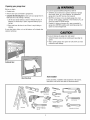
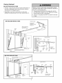
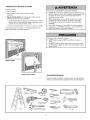
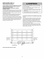
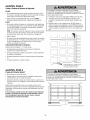
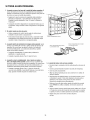
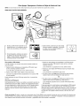
Preparing your garage door
Beforeyou begin:
• Disablelocks.
• Removeany ropesconnectedto garage door.
• Completethe followingtest to make sureyour garagedoor is
balancedand is not sticking or binding:
1. Lift the door about halfwayas shown. Releasethe door. If
balanced, it should stay in place,supported entirely by its
springs.
2. Raiseand lowerthe door to seeif there is any binding or
sticking.
If your door binds, sticks, or is out of balance,call a trained door
systems technician.
To prevent possible SERIOUSINJUREor DEATH:
• ALWAYScalla trained door systems technician if garage
door binds, sticks, or is out of balance.An unbalanced
garage door may NOTreversewhen required.
• NEVERtry to loosen, move or adjust garagedoor, door
springs, cables,pulleys, bracketsor their hardware,ALL of
which are under EXTREMEtension.
• DisableALL locks and remove ALL ropes connectedto
garage door BEFOREinstalling and operating garagedoor
opener to avoid entanglement.
To prevent damageto garagedoor and opener:
• ALWAYSdisablelocks before installing and operating the
opener.
• ONLYoperategaragedoor openerat 120V, 60 Hzto avoid
malfunction and damage.
SectionalDoor
One-Piece Door
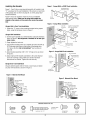
Tools needed
Duringassembly, installation and adjustment of the opener,
instructions will call for handtools as illustrated below.
Stepladder
Level (optional)
Tape Measure
Drill 3/16", 5/16"
i_ and 5/32"
0
[_1_ Sockets and Wrench
--U 1/2", 5/8", 7/16", 9/16"
and 1/4"
Pencil
Wire Cutters
Screwdriver
Hack Saw
Adjustable End Wrench

P_nnmg
Identify the type and height of your garagedoor. Surveyyour
garageareato seeif any of the conditions below applyto your
installation. Additional materials may be required.You may find it
helpfulto refer backto this pageand the accompanying
illustrations asyou proceedwith the installation ofyour opener.
Dependingon your requirements, thereare several installation
steps which may call for materials or hardwarenot included in the
carton.
• Installation Step 1- Lookat the wall or ceiling abovethe garage
door. The headerbracketmust besecurely fastenedto structural
supports.
• Installation Step5 - Doyou havea finished ceiling in your
garage? If so, a support bracketand additional fastening
hardwaremay be required.
• Installation Step 10- Dependingupon garage construction,
extension bracketsor wood blocks may be neededto install
sensors.
• Installation Step 10- Alternate floor mounting of the safety
reversingsensor will require hardwarenot provided.
Doyou havean accessdoor in addition to the garagedoor? If
not, Model53702 OutsideQuick Releaseis required.See
Accessories page.
Look atthe garagedoor where it meetsthe floor. Any gap
betweenthefloor and the bottom of the door must not exceed
1/4" (6mm). Otherwise,the safety reversalsystem may not
work properly. SeeAdjustment Step3. Flooror door should be
repaired.
SECTIONALDOORINSTALLATIONS
• Doyou havea steel,aluminum, fiberglass or glass paneldoor?
If so, horizontal and vertical reinforcement is required
(Installation Step11).
• The openershould be installed abovethe center of the door. If
there is a torsion spring or center bearing platein theway of the
headerbracket, it may be installedwithin 4 feet (1.2 m) to the
left or right of the door center.See Installation Steps 1 and 11.
• If your door is more than 7 feet (2.1 m) high, see rail extension
kits listed on Accessoriespage.
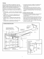
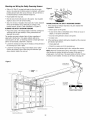
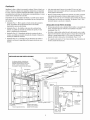
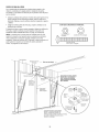
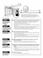
SECTIONALDOORINSTALLATION
Horizontal and vertical reinforcement
is neededfor lightweight garage doors
(fiberglass, steel, aluminum, door with
glass panels, etc.). Seepage 23 for details.
Header Wall
Slack in chain tension
is normal when
garage door is closed.
Extension Spring
OR
Torsion Spring
FINISHEDCEILING
Support bracket &
fastening hardware
is required.
See page 16.
Motor unit
Vertical
Centerline
ofGarage
Door
Wall-
mounted
Door
Control
4
ty Reversing Sensor
Gap between floor
and bottom of door
must not exceed 1/4" (6 mm).
Safety Reversing
Sensor
Access Door
0
_ Header CLOSED POSITION
Bracket
/ Trolley
.......r.......
Garage /
_/._ _ G_age // Chain
_ r-',-_-/ Spring_o/
_////._1/////A /j/Y-_tr_irght --B_]eera%nCy
//_/ Arm Rope&Handle
He_der __Curved d'm
Wall _"N_I \ Door
L\N I Door Arm
Garage__l Bracket
Door

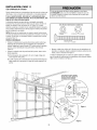
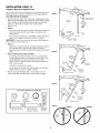
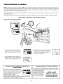
Planning (Continued)
ONE-PIECEDOORINSTALLATIONS
• Generally,a one-piecedoor doesnot require reinforcement. If
your door is lightweight, referto the information relating to
sectional doors in Installation Step11.
• Dependingon your door's construction, you may need
additional mounting hardwarefor the door bracket(Step 11).
Without a properlyworking safety reversalsystem, persons
(particularly small children) could be SERIOUSLYINJUREDor
KILLEDby a closing garage door.
• The gap betweenthe bottom of the garagedoor and the
floor MUSTNOTexceed1/4" (6 mm). Otherwise,the safety
reversalsystem may NOTwork properly.
• Thefloor orthe garagedoor MUSTbe repairedto eliminate
the gap.
ONE-PIECEDOORWITHOUTTRACK
Header
Wall
Slack in chain tension
is normal when
garage door is closed.
__ Wall-
mounted
}oor
;ontr
I
_afeb _-
ReversingSensor
andbottomof
Safety doormustnotexceed1/4"(6mm)
ReversingSensor
FINISHEDCEILING
Support bracket
& fastening
hardware is required.
See page 16.
Access
Door
0
Motor Unit
CLOSEDPOSITION
Cable
Pulley Bracket
Trolley
Door j j
I I Emergency
. Release
_ed RR_lDeeaS_Hand,e
_nr-- Hope_ uanole
,_ Arm Arm
Garage
Door
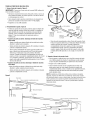
ONE-PIECEDOORWITHTRACK
_. _ _ Slack in chain tension is normal when _
Header
Fo eeo wa,,
IlI II !lira I I I Garage--
__ Door
andbottomofdoor Sensor
----"- Safety must not
/
Reversing Sensor exceed 1/4" (6 mm) /
d
5
CLOSEDPOSITION
Cable Cable Trolley Chain
Pulley Bracket I I_
.
"X'_ Header Curved _ R!il
Bracket Door Arm "_-/ I ....
Y////i:J Door Straight ,..J...
N i c,otooor
"//A Arm
EmergencyRelease
Rope & Handle

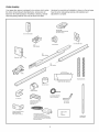
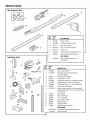
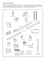
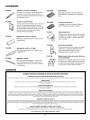
CartonInventory
Your garage door opener is packagedin two cartonswhich contain
the motor unit and all parts illustrated below. Accessorieswill
dependon the model purchased.If anything is missing, carefully
checkthe packing material. Parts may be stuck in the foam.
Hardwarefor assembly and installation is shown on the next page.
Savethe carton and packing material until installation and
adjustment iscomplete.
SECURITY÷_
3-Function Remote Control
with Visor Clip (2)
Door Control Button
Door Bracket Plate
Mounting Bracket and
With Square Holes (2) The Protector System® Literature
(2) Safety Reversing Sensors Straight Door
(1 Sending Eyeand 1 Receiving Eye)
with 2-Conductor White & White/Black Arm Section
Bell Wire attached

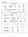
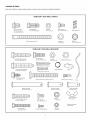
HardwareInventory
Separateall hardwareand group as shown below for theassembly and installation procedures.
ASSEMBLYHARDWARE
Washered Bolt Hex Bolt Nut
5/16"-18xl/2" (2) 5/16"-18x7/8" (3) 5/16"-18 (5)
(mounted in motor unit)
Threaded
Trolley Shaft (1)
Carriage Bolts
1/4"-20xl/2" (4)
@
Lock Washer
5/16" (4)
i
Master Link (2)
@
Lock Nut
1/4"-20x7/16" (4)
5/16"-9xl -5/8" (2)
INSTALLATIONHARDWARE
Hex Bolt
5/16"-18x7/8" (4) Nut 5/16"-18 (6) Lock Washer 5/16" (6)
0
Ring
Fastener (3)
Self-Threading Screw
1/4"-14x5/8" (2)
Clevis Pin
5/16"x2-3/4" (1)
1/4 x1-1/2" (4)
IIIIIIIIIIIIIIIIIID
Hex Bolt
1/4-20x1-1/2" (2)
CarriageBolt
5/16"-18x2-1/2"(2)
Carriage Bolts
1/4"-20xl/2" (4)
Screw
#10-32x3/8" (4)
Clevis Pin
5/16"x1-1/4"(1)
©
Lock Nut
1/#'-20 (4)
@
Lock Nut
#10x32 (4)
oB
Handle
I//11/f
Drywall Anchors (2) Rope
°D
Clevis Pin
5/16"x1" (1)
Wing Nut
1/4x20 (2)
Insulated Staples
(Not shown)

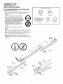
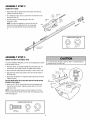
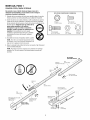
ASSEMBLY STEP 1
Assemble the Rail and
Attach the Cable Pulley Bracket
To avoidinstallationdifficulties,do notrunthegaragedoor
openeruntil instructedto doso.
1. Align the three rail sections on a flat surfaceexactly asshown.
Front and back sections are interchangeablefor easeof
assembly.
2. Insert the carriagebolts so thesquare bolt
necksseat in the squareholes in the rail
U
sections and pass through the round holes in
thecenter section rail. Make sure holtnecks
areseatedin the squareholesandrails are
alignedbeforeyoutightenlocknuts.
Improper assembly cancausejerky trolley
operation, noise and/or nuisancedoor
reversals.
3. Assemblelock nuts, ensurealignment and
tighten.
NOTE:If rail is not assembled exactlyasshown, trolley will not
travel smoothly along length of rail or it will hit against nuts.
4. Position the cable pulleybracketon thefront end of the rail as
shown. Fastensecurelywith the hardwareshown.
NOTE:Whentightening thebolts, be sure to keepbracket
parallel to the rail. Otherwise, therail may bow whenthe opener
is operated.
HARDWARESHOWNACTUALSIZE
Q
Lock Nut
1/4"- 20 x 7/16"
,1111111111D
Hex Screw
5/16"- 18 x 7/8"
Carriage Bolts
1/4"- 20x 1/2"
Nut
5/16"- 18
RAILBACK
(TOOPENER)
Rail
(CenterSection)
1/4" Lock Nut
\
\
Brace
Rail
(End Section)
Rail
(End Section)
Cable pulley bracket
attaches to FRONT
ENDof Rail
RAILFRONT
(TODOOR)
Brace
Square Carriage
Bolt Holes
Lock Washer
5/16"

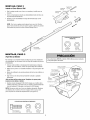
ASSEMBLY STEP 2
Install the Trolley
Attachthe trolley threadedshaftto thetrolley with the lock
washer and nuts as shown.
Lock Inner Nut
Asa temporary stop, insert a screwdriver into the hole in the Washer5/16"
front end of the rail. 5/16"
Slidethe trolley assembly along the rail to the Outer Nut _ Trolley __
screwdriver stop. 5/16" _j Thh_ded _""_'_ T_lle
NOTE:If trofleyhits against any nuts on the rail, the _ _ _ /.2_"'" _ Y
bolts and nuts wereattachedfrom the wrongside Trolley ,_ _ /_/ /
and must be reposifioned.ReviewAssembly Step ( _-/_ _ __/ P
'
/_ Nut
St°O 5/16-18
Lock Washer
5/16"
ASSEMBLY STEP 3
Attachthe Rail totheMotorUnit
Toavoid installation difficulties, do not run the garagedoor opener
until instructed to do so.
• Placethe opener on packing materialto protect the cover. For
convenience,put a support under the cablepulley bracket.
• Removethe two washered bolts mounted in top of motor unit.
• Align the holesin the backsection of the rail with the holesin
the motor unit.
• Fastenthe rail with the two washered bolts previously removed.
Tighten securely.
Use onlythesebolts! Useof anyotherbolts will causeserious
damageto dooropener.
• Inserta 5/16"-18x7/8" hex bolt into the cover protection bolt
hole in the rail as shown. Tighten securelywith a 5/16" lock
washer and nut.
NOTE:Thisbolt prevents trolley over-traveLKeepa 2" (5 mm)
minimum betweenthe trolley and this bolt whenadjusting travel
limits (seepage27).
HARDWARESHOWNACTUALSIZE
Hex Bolt Nut
5/16"-18x7/8" 5/16"-18
Lock Washer
5/16"
To avoid serious damageto opener,ONLYusebolts/fasteners
mounted in top of motor unit.

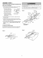
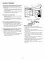
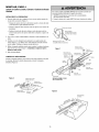
ASSEMBLY STEP 4
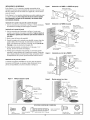
Install the Chain/CableandAttachthe SprocketCover
INSTALLINGTHECHAIN/CABLE
1. Pullthe cable loop from the carton andfasten it to thetrolley
with a master link from the hardwarebag (Figure1).
• Push pins of master link LeaveChain&
bar through cableloop and
hole in front end of trolley.
• Push masterlink capover
pins and past pin notches.
• Slide clip-on spring over
capand onto pin notches
until both pins are securely
locked in place.
Cable Inside
Dispensing
Cartonto
king
KeepChain and Cable
Taut When Dispensing
2. With the trolley against the screwdriver, dispensethe cable
around the pulley.
3. Continue along the rail and aroundthe motor unit sprocket
(Figure2). The sprocket teeth must engagethe chain. Continue
forward to the trolley threadedshaft.
4. Usethe second master link to connect the chainto the flat end
of the shaft (Figure1). Checkto makesurethe chainis not
twisted.
5. Removethe screwdriver.
ATTACHINGTHESPROCKETCOVER
Insert the backtab in the slot on the back of the mounting plate.
Squeezethe cover slightly and insert the front tab (Figure3).
To avoid possible SERIOUSINJURYto fingers from moving
garagedoor opener:
• ALWAYSkeephandclear of sprocket while operatingopener.
• Securelyattachsprocket cover BEFOREoperating.
FigureI MasterLink
Clip-On Spring,
Master"_
Master Link Flat end Link Cap i _ -
Clip-On Spring , of Trolley _ yf
Master _ _ Threaded Shaft.x¢_.,, y._..
_boLi:k Cap[_, _'_ _,i" _Rt! Chain
f -¢--_._ d:Y'<"-Master
INSTALLCHAIN& CABLE
INTHIS DIRECTION
Figure3
Sprocket
Cover
Figure2 MotorUnit
Sprocket
10

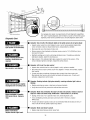
ASSEMBLY STEP 5
Tightenthe Chainand Cable
• Spin the inner nut and lock washerdown the threadedshaft,
awayfrom thetrolley.
• Totighten the chain, turn outer nut in the direction shown. As
youturnthe nut,keepthe chainfromtwisting.
• Whenthe chain is approximately 1/2" (13 mm) abovethe base
of the rail at its midpoint, re-tighten the inner nutto securethe
adjustment.
Sprocket noisecanresultif chainis eithertoo looseor tootight.
Wheninstallation is complete,you may notice some chain droop
with the door closed.This is normal. If the chain returns to the
position shown whenthe door is open, do not re-adjust thechain.
NOTE:During future maintenance,ALWAYSpuff the emergency
releasehandle to disconnect trolley beforeadjusting chain.
Youhavenowfinishedassemblingyourgaragedooropener.
Pleaseread thefollowingwarningsbeforeproceedingtothe
installationsection.
Lock
OuterNut Washer InnerNut
To Tighten Outer Nut _ ._l._,J __
rL_ ...............'__"",_'_"'T o T,'g'ht'e'n....
oj Inner Nut
Chain
----1/2" (13 mm)
Base!f Rail
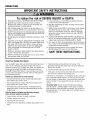
INSTALLATION
IMPORTANTINSTALLATIONINSTRUCTIONS
ToreducetheriskofSEVEREINJURYorDEATH:
1. READAND FOLLOWALL INSTALLATIONWARNINGSAND
INSTRUCTIONS.
2. Install garagedoor opener ONLYon properly balancedand
lubricated garagedoor. An improperly balanceddoor may
NOTreversewhen required and could result in SEVERE
INJURYor DEATH.
3. ALL repairsto cables,spring assembliesand other
hardware MUSTbe madeby a trained door systems
technician BEFOREinstalling opener.
4. DisableALL locks and removeALL ropes connectedto
garagedoor BEFOREinstalling openerto avoid
entanglement.
5. Install garagedoor opener 7 feet (2.13 m) or more above
floor.
6. Mount emergency releasewithin reach, but at least 6 feet
(1.8 m) abovethe floor and avoiding contactwith vehicles
to avoidaccidental release.
7. NEVERconnectgarage door opener to powersource until
instructed to do so.
8. NEVERwearwatches, rings or loose clothing while
installing or servicing opener.They could be caught in
garage door or opener mechanisms.
9. Install wall-mounted garagedoor control:
• within sight of the garage door.
• out of reachof children at minimum height of 5 feet
(1.5 m).
• awayfrom ALL moving parts of the door.
10. Placeentrapment warning labelon wall next to garage
door control.
11. Placemanual release/safetyreversetest label in plain
view on inside of garage door.
12. Uponcompletion of installation, test safety reversal
system. Door MUST reverseon contact with a 1-1/2"
(3.8 cm) high object (or a 2x4 laid flat) on the floor.
11

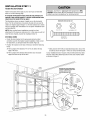
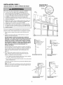
INSTALLATION STEP 1
Determinethe HeaderBracketLocation
To prevent possible SERIOUSINJURYor DEATH:
• HeaderbracketMUSTbe rigidly fastenedto structural
support on headerwall or ceiling, otherwise garagedoor
might NOTreversewhen required. DONOTinstall header
bracketover drywall.
• Concreteanchors MUSTbe used if mounting headerbracket
or 2x4 into masonry.
• NEVERtry to loosen, move or adjust garagedoor, springs,
cables,pulleys, brackets,or their hardware,ALL of which are
under EXTREMEtension.
• ALWAYScall atrained door systems technician if garage
door binds, sticks, or is out of balance.An unbalanced
garagedoor might NOTreversewhen required.
nstallation proceduresvary according to garagedoor types.
Follow the instructions which applyto your door.
1. Closethe door and mark the insidevertical centerline of the
garagedoor.
2. Extendthe line onto the headerwall abovethe door.
Youcanfastenthe headerbracketwithin4 feet (1.22 m) of
theleft or rightofthe doorcenter onlyif a torsionspringor
centerbearingplate isin the way;or youcanattachittothe
ceiling(see page 13) when clearanceisminimal. (It may be
mountedonthewall upsidedownif necessary,to gain
approximately1/2"(13 ram).
If you needto install the headerbracketon a 2x4 (on wall or
ceiling), uselag screws (not provided) to securely fastenthe
2x4to structural supports asshown hereand on page 13.
3. Openyour door to the highest point of travel as shown. Draw an
intersecting horizontal line on the headerwall abovethe high
point:
• 2"(5 cm) abovethe high point for sectionaldoor and one-
piecedoor with track.
• 8"(20 cm) abovethe high point for one-piecedoor without
track.
This height will providetravel clearancefor the top edgeofthe
door.
NOTE:If thetotal number of inches exceedstheheight availablein
your garage,use themaximum height possible, or referto page 13
for ceiling installation.
Unfinished
Ceiling
Header Wall
VerticalCenterline
ofGarageDoor
HeaderWall
HighestPoint
of Travel
Sectional doorwith curved track
L_Wall
:_ )
Highest
Point
ofTravel
Hardware
One-piecedoorwithouttrack:
jambhardware
OPTIONAL
CEILING
MOUNT
FOR
HEADER
BRACKET
2x4
Structural
Supports
H
HeaderWall Track
t
ofTravel
One-piece door with horizontal track
HeaderWall
',- 8" (20cm)
L____:=.;_,
Door
:l
Pivot
One-piece door without track:
pivot hardware
', Highest
,, Point
" of Travel
12

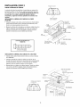
INSTALLATION STEP 2
Install theHeaderBracket
You canattachthe headerbracketeitherto thewall abovethe
garagedoor, or to the ceiling. Followthe instructions which will
work best for your particular requirements. Donot install the
headerbracketover drywall. If installingintomasonry,use
concreteanchors(notprovided).
WALLHEADERBRACKETINSTALLATION
• Centerthe bracketon the vertical centerlinewith the bottom
edgeof the bracket on the horizontal line asshown (with the
arrow pointing toward the ceiling).
• Mark the vertical set of bracket holes(do not usethe holes
designatedfor ceiling mount). Drill 3/16" pilot holesand fasten
the bracketsecurelyto a structural support with the hardware
provided.
HARDWARESHOWNACTUALSIZE
LagScrew
5/16"x9x1-5/8"
CEILINGHEADERBRACKETINSTALLATION
• Extendthevertical centerline onto the ceiling as shown.
• Centerthe bracketon the vertical mark, no more than 6"(15 cm)
from the wall. Makesurethe arrow is pointing toward the wall.
Thebracketcan be mounted flush againstthe ceiling when
clearanceis minimal.
• Mark the side holes. Drill 3/16" pilot holesand fasten bracket
securelyto a structural support with the hardwareprovided.
Ceiling Mounting Holes
CEILI MOiM'_UN NLY
o@o
Wall Mounting Holes
G MOUNT ONLY
Optional_
Wail MountingHoles
Header
-- Wall
2x4
Structural
Support
Horizontal
Line _ /
/
/
/
/
.. 1/
HighestPoint of
Garage DoorTravel
Vertical
Centerline
of Garage Door
LagScrews
5/16"-9xl-5/8"
Door Spring
Garage
- Door -
Vertical
Centerline
ofGarageDoor
* _" __ __ _* _ _ //_ - FinishedverticaiCeiling-
_ _ _/_ Header Centerline
Bracket of Garage Door
6" (15 cm) Maximur
Door
Spring
LagScrews
5/16"-9xl -5/8"
HeaderWall
\ of Garage Door
13

Header Wall
Bracket
Cable
Pulley
Bracket
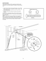
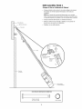
INSTALLATION STEP 3
Attachthe Rail to the HeaderBracket
• Position the opener on the garagefloor below the header
bracket. Usepacking material as a protective base. NOTE:If the
door spring is in the wayyou'll needhelp. Havesomeone hold
the openersecurely on a temporary support toaflow the raftto
clear thespring.
• Position the rail bracketagainst the headerbracket.
• Align the bracketholes and join with a clevis pin as shown.
• Insert a ring fastenerto secure.
-- Rail
Clevis Pin
5/16"x2-3/4"
Ring Fastener
Header _.
Bracket 0
i
Cable
Pulley
Bracket
Rail
__ Garage
Door
-- Openercartonor
TemporarySupport
HARDWARESHOWNACTUALSIZE
Clevis Pin
5/16"x2-3/4"
0
Ring Fastener
14

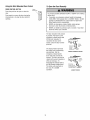
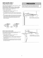
INSTALLATION STEP 4
Positionthe Opener
Follow instructions which applyto your door type as illustrated.
SECTIONALDOORORONE-PIECEDOORWITH TRACK
A 2x4 laid flat is convenientfor setting an ideal door-to-rail
distance.
• Removefoam packaging.
• Raisethe openeronto a stepladder.You will needhelp at this
point if the ladder is not tall enough.
• Openthedoor all the way and placea 2x4 laidflat on thetop
section beneaththe rail.
• If the top section or panelhits thetrolley when you raise
thedoor, pull down on the trolley releasearm to disconnect
inner and outer sections. Slide the outertrolley toward the
motor unit. Thetrolley can remaindisconnected until
Installation Step12 iscompleted.
Trolley
v " _ ' -- ReleaseArm --
ENGAGED RELEASED
To prevent damageto garagedoor, rest garagedoor opener rail
on 2x4 placedon top section of door.
Rail
2x4 is used to determine
the correct mounting height
from ceiling.
ONE-PIECEDOORWITHOUTTRACK
A 2x4 on its side is convenientfor setting an ideal door-to-rail
distance.
• Removefoam packaging.
• Raisethe openeronto a stepladder.You will needhelp at this
point if the ladder is not tall enough.
• Openthe door all the way and placea 2x4 on its side on the top
section of the door beneaththe rail.
• Thetop of the door should be levelwith the top of the motor
unit. Do not position the opener morethan 4" (10 cm) abovethis
point.
i
Header
2x4 is used to determine
the correct mounting height
from ceiling.
15

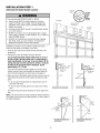
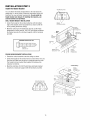
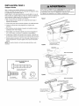
INSTALLATION STEP 5
HangtheOpener
Three representativeinstallations are shown. Yours may be
different. Hangingbrackets should be angled (Figure1) to provide
rigid support. Onfinished ceilings (Figure2 and Figure3), attach a
sturdy metal bracketto structural supports beforeinstalling the
opener.This bracket andfastening hardwareare not provided.
1. Measurethe distancefrom eachside of the motor unit to the
structural support.
2. Cut both piecesof the hanging bracketto required lengths.
3. Drill 3/16" pilot holes in the structural supports.
4. Attachone end of eachbracketto a support with
5/16"-18xl -7/8" lagscrews.
5. Fastenthe openerto the hanging bracketswith 5/16"-18x7/8"
hexbolts, lock washersand nuts.
6. Checkto makesurethe rail is centered overthe door (or in
line with the headerbracket if the bracketis notcentered above
thedoor).
7. Removethe 2x4. Operatethe door manually. If thedoor hits the
rail, raisethe headerbracket.
NOTE:DONOTconnectpower to openerat this time.
HARDWARESHOWNACTUALSIZE
,lllllllllID@
Hex Bolt
5/16"-18x7/8" Nut 5/16"-18 LockWasher 5/16"
To avoid possible SERIOUSINJURYfrom a falling garagedoor
opener,fasten it SECURELYto structural supports of the
garage.Concreteanchors MUSTbe usedif installing ANY
brackets into masonry.
Figure I ructural
Supports
Measure _
Distance
Lag Screws
5/16"-18xl -7/8"
Bolt 5/16"-18x7/8"
Lock Washer 5/16"
Nut 5/16"-18
Bolt 5/16"-18x7/8 _-"
Lock Washer 5/16"
Nut 5/16"-18
FINISHEDCEILING
Provided)
Lock Washer 5/16"
Nut 5/16"-18
gScrews
FINISHEDCEILING
Bolt 5/16"-18x7/8"
Lock Washer 5/16"
Nut 5/16"-18
, (Not Provided)
Bolt 5/16"-18x7/8"
Lock Washer 5/16"
16

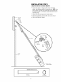
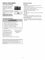
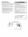
INSTALLATION STEP 6
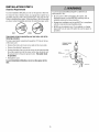
Install theDoorControl
Locatedoor control within sight of door, at a minimum heightof 5
feet (1.5 m) where small children cannot reach,awayfrom moving
parts of door and door hardware. If installing into drywall, drill
5/32" holesand usethe anchors provided.
1. Strip 1/4" (6 mm) of insulationfrom one endof bell wire and
connectto the two terminal screws on back of door control by
color: white to 2 and white/red to 1.
2. DoorControlButton:Fastensecurelywith screws 6ABx1-1/2".
3. (Forstandardinstallationonly)Runbell wire upwall and
acrossceiling to motor unit. Useinsulated staplesto secure
wire in severalplaces.Do not piercewire with a staple, creating
a short or opencircuit.
4. Connectthe bell wire to theterminal screws on the motor unit
panel:white to 2;white/red to 1.
5. Position the antennawire asshown.
To prevent possible SERIOUSINJURYor DEATHfrom
electrocution:
• Besure power is NOTconnectedBEFOREinstalling door
control.
• ConnectONLYto 24 VOLTlow voltage wires.
To prevent possible SERIOUSINJURYor DEATHfrom a closing
garagedoor:
• Install door control within sight of garagedoor, out of reach
of children at a minimum height of 5 feet (1.5 m), and away
from ALL moving parts of door.
• NEVERpermit children to operateor playwith door control
push buttons or remote control transmitters.
• Activate door ONLYwhen it can be seenclearly,is properly
adjusted,and thereare no obstructions to door travel.
• ALWAYSkeepgaragedoor in sight until completely closed.
NEVERpermit anyoneto cross path of closing garagedoor.
HARDWARESHOWNACTUALSIZE
Drywall Anchors
(drywall installation)
Insulated Staples
(Not shown)
Terminal
Screws
(BACKVIEW)
DOORCONTROLBUTTON
2-Conductor
Bell Wire
Opener
Terminal Screws
Back Panel
of Opener
Antenna
17

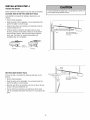
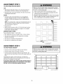
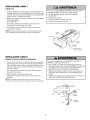
INSTALLATION STEP 7
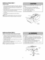
Install theLight
• Install a 75 watt maximum light bulb in thesocket. Lightsize is
A19,standard neck only Thelight will turn ONand remain lit for
approximately 4-1/2 minuteswhen power is connected. Then
the light will turn OFF.
• Apply slight pressureon the sides of the lensand slide the tabs
into the slots in the end panel (Seeillustration).
• To remove,reversethe procedure. Usecareto avoidsnapping
off lenstabs.
• UseA19, standard neck garagedoor opener bulbs for
replacement.
NOTE:Useonly a standard light bulb. Theuse ofa short neck or
speciafitylight bulb may overheatthe endpanelor light socket.
To prevent possible OVERHEATINGof the endpanelor light
socket:
• DONOTuseshort neckor specialty light bulbs.
• DONOTuse halogenbulbs. UseONLYincandescent.
To prevent damageto the opener:
• DONOTuse bulbs larger than 75W.
• ONLYuseA19 size bulbs.
LensGuide
Light
Lens Slot
LensTab
75Watt Max.
Light Bulb
INSTALLATION STEP 8
Attachthe EmergencyRe/easeRopeand Hand/e
• Threadone end of the rope through the holein thetop of the
redhandle so "NOTICE"readsright sideup asshown. Secure
with an overhandknot at least 1" (25 mm) from the end of the
ropeto preventslipping.
• Threadthe other endof the ropethrough the hole in the release
arm of the outer trolley.
• Adjust rope length sothe handleis 6 feet (1.8 m) abovethe
floor. Securewith an overhandknot.
NOTE:If it is necessaryto cut therope, heatsealthe cut end with
a match or lighter to prevent unraveling.
To prevent possible SERIOUSINJURYor DEATHfrom a falling
garagedoor:
• If possible, useemergencyreleasehandleto disengage
trolley ONLYwhengarage door is CLOSED.Weakor broken
springs or unbalanceddoor could result in an open door
falling rapidly and/or unexpectedly.
• NEVERuseemergency releasehandleunless garage
doorway is clear of persons and obstructions.
• NEVERuse handleto pull door open or closed. If rope knot
becomesuntied, you could fall.
Tro,,e %h° nd
Rope -- ReleaseArm
N_ _ Emergency
Overhand _ ReleaseHandle
not
18

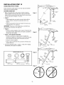
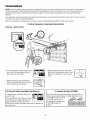
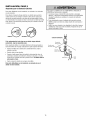
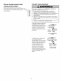
INSTALLATION STEP 9
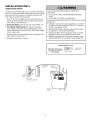
ElectricalRequirements
To avoid installation difficulties, do not run the opener atthis time.
To reducethe risk of electric shock, your garagedoor opener hasa
grounding type plug with athird grounding pin. This plug will only
fit into agroundingtype outlet. If the plug doesn't fit into the outlet
you have,contact a qualified electricianto installthe proper outlet.
RIGHT @ WRONG
If permanent wiring isrequiredby yourlocal code,refer tothe
following procedure.
To make a permanent connectionthrough the 7/8" holein the top
of the motor unit:
• Removethe motor unit cover screws and set the cover aside.
• Removethe attached3-prong cord.
• Connectthe black (line) wire to the screw on the brassterminal;
thewhite (neutral) wire to the screw on the silver terminal; and
theground wire to the green ground screw. The opener must
be grounded.
• Reinstallthe cover.
To avoidinstallationdifficulties,do notruntheopenerat this
time.
To prevent possible SERIOUSINJURYor DEATHfrom
electrocution or fire:
• Besure power is NOTconnectedto the opener,and
disconnect power to circuit BEFOREremoving coverto
establishpermanent wiring connection.
• Garagedoor installation and wiring MUSTbe in compliance
with ALL local electricaland building codes.
• NEVERusean extension cord, 2-wire adapter,or change
plug in ANYway to makeit fit outlet. Besure the opener is
grounded.
PERMANENTWIRING
CONNECTION
GroundTab
Green
GroundScrew
GroundWire Wire
White Wire BlackWire
19

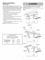
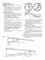
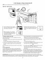
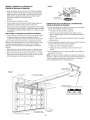
INSTALLATION STEP 10
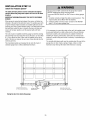
Install TheProtectorSysterr
The safetyreversingsensormustbeconnectedand aligned
correctlybeforethegaragedooropenerwill movein the down
direction.
IMPORTANTINFORMATIONABOUTTHESAFETYREVERSING
SENSOR
When properly connectedand aligned,the sensor will detectan
obstacle in the path of its electronic beam.Thesending eye(with
an green indicator light) transmits an invisiblelight beamto the
receivingeye(with a green indicator light). If an obstruction breaks
the light beamwhile the door is closing, the door will stop and
reverseto full open position, and the opener lights will flash
10 times.
The units must be installed insidethe garage sothat the sending
and receivingeyesface eachother acrossthe door, no more than
6" (15 cm) abovethe floor. Eithercan be installed on the left or
right of the door as long asthe sun nevershines directly into the
receivingeyelens.
The mounting bracketsare designedto clip onto thetrack of
sectional garagedoors without additional hardware.
Besure poweris NOTconnectedto the garagedoor opener
BEFOREinstalling the safety reversing sensor.
To prevent SERIOUSINJURYor DEATHfrom a closing garage
door:
• Correctly connect and align the safety reversing sensor.This
requiredsafety device MUSTNOTbedisabled.
• Installthe safety reversingsensor so beam is NOHIGHER
than 6"(15 cm) abovegaragefloor.
If it is necessaryto mount the units on thewall, the brackets must
be securelyfastenedto a solid surface such asthe wall framing.
Extensionbrackets (seeaccessories)are availableif needed.If
installing in masonryconstruction, add a pieceof wood at each
location to avoiddrilling extra holes in masonry if repositioning is
necessary.
Theinvisible light beam pathmust be unobstructed. No partof the
garagedoor (or door tracks, springs, hinges, rollers or other
hardware)may interrupt the beamwhile the door isclosing.
Safety Reversing Sensor
6" (15cm) max. above floor
Invisible Light Beam
Protection Area
Safety Reversing Sensor
6" (15 cm) max. above floor
Facingthe doorfrom insidethe garage
2O
Page is loading ...
Page is loading ...
Page is loading ...
Page is loading ...
Page is loading ...
Page is loading ...
Page is loading ...
Page is loading ...
Page is loading ...
Page is loading ...
Page is loading ...
Page is loading ...
Page is loading ...
Page is loading ...
Page is loading ...
Page is loading ...
Page is loading ...
Page is loading ...
Page is loading ...
Page is loading ...
Page is loading ...
Page is loading ...
Page is loading ...
Page is loading ...
Page is loading ...
Page is loading ...
Page is loading ...
Page is loading ...
Page is loading ...
Page is loading ...
Page is loading ...
Page is loading ...
Page is loading ...
Page is loading ...
Page is loading ...
Page is loading ...
Page is loading ...
Page is loading ...
Page is loading ...
Page is loading ...
Page is loading ...
Page is loading ...
Page is loading ...
Page is loading ...
Page is loading ...
Page is loading ...
Page is loading ...
Page is loading ...
Page is loading ...
Page is loading ...
Page is loading ...
Page is loading ...
Page is loading ...
Page is loading ...
Page is loading ...
Page is loading ...
-
 1
1
-
 2
2
-
 3
3
-
 4
4
-
 5
5
-
 6
6
-
 7
7
-
 8
8
-
 9
9
-
 10
10
-
 11
11
-
 12
12
-
 13
13
-
 14
14
-
 15
15
-
 16
16
-
 17
17
-
 18
18
-
 19
19
-
 20
20
-
 21
21
-
 22
22
-
 23
23
-
 24
24
-
 25
25
-
 26
26
-
 27
27
-
 28
28
-
 29
29
-
 30
30
-
 31
31
-
 32
32
-
 33
33
-
 34
34
-
 35
35
-
 36
36
-
 37
37
-
 38
38
-
 39
39
-
 40
40
-
 41
41
-
 42
42
-
 43
43
-
 44
44
-
 45
45
-
 46
46
-
 47
47
-
 48
48
-
 49
49
-
 50
50
-
 51
51
-
 52
52
-
 53
53
-
 54
54
-
 55
55
-
 56
56
-
 57
57
-
 58
58
-
 59
59
-
 60
60
-
 61
61
-
 62
62
-
 63
63
-
 64
64
-
 65
65
-
 66
66
-
 67
67
-
 68
68
-
 69
69
-
 70
70
-
 71
71
-
 72
72
-
 73
73
-
 74
74
-
 75
75
-
 76
76


Craftsman 139536481DM Owner's manual
- Category
- Garage Door Opener
- Type
- Owner's manual
Ask a question and I''ll find the answer in the document
Finding information in a document is now easier with AI
in other languages
Related papers
-
Craftsman 139.536481DM Owner's manual
-
-
-
-
-
-
Craftsman 13953662SRT2 Owner's manual
-
-
-
Other documents
-
 Steel-Craft 1255SCR Owner's manual
-
Sears 139.53535SRT1 User manual
-
Chamberlain 2255-2C 1/2 HP User manual
-
-
Chamberlain 211X User manual
-
-
Chamberlain 1210E FS2 User manual
-
 Merik 790LMK Owner's manual
-
Chamberlain PD432DM User manual
-
 2 x 4 Basics 90158 Operating instructions


