
INSTALLATION MANUAL
Professional ® PH SERIES Wall Hoods
MANUEL D'INSTALLATION
Hottes murales de gamme PH Professional ®
MANUAL DE INSTALACION
Campanas de pared de la serie
PH Professional ®
Models/
Modeles /
Modelos:
PH30
PH36
PH42
PH48
PH54

Table of Contents
Introduction ................................... 1
Safety Instructions .............................. 1
Before you Begin ................................................... 1
Installation .................................... 3
Considerations Before Installing Hood .................................. 3
Appliance Installation ................................................ 4
Wall Mount Installation ............................................... 5
Assembly and Installation of the Duct Covers ............................ 8
Cabinet Installation .................................................. 8
Installing an Integral Blower, Model VTN630C or VTN1030C ................ 9
Wire Routing Instruction ........................ 11
Vertical Discharge .................................................. 11
Horizontal Discharge ............................................... 11
Wiring the Hood with an Integral Blower ............................... 12
Remote Blower Installation .......................................... 12
Wiring the Hood with a Remote Blower ................................ 12
Wiring the Hood with an Inline Blower ................................. 13
This Thermador Appliance is made by
BSH Home Appliances Corporation
5551 McFadden Ave.
Huntington Beach, CA 92649
Questions?
1-800-735-4328
www.thermador.com
We look forward to hearing from you!

_j[__ _ _ii_11__ ...................................................................................................................................................................................................................................................................................................................................................................................................,_
Introduction
This manual provides the proper installation instructions for
two styles of Thermador, PH Series Professional ® Wall
Hoods:
• Five 27"-depth models, with widths of 30", 36", 42", 48",
and 54". This model series features brushed stainless-
steel canopy with halogen lamps and heat lamps.
• Three 24"-depth models, with widths of 30", 36", and
48". This model series features brushed stainless-steel
canopy with halogen lamps.
All hoods require the choice of an Integral Blower
(VTN630C and VTN1030C), Inline Blowers (VTI610D and
VTI1010D), or a Remote Blower (VTR630D, VTR1030D,
and VTR1330E). All blower models are sold separately.
All Hood models are rated for 120 VAC, using a 30 Amp
circuit breaker.
Safety Instructions
Important Safety Instructions
READ AND SAVE THESE INSTRUCTIONS
APPROVED FOR ALL RESIDENTIAL APPLIANCES
FOR RESIDENTIAL USE ONLY
Before you Begin
IMPORTANT: Save these Instructions for the Local Gas
Inspector's use.
INSTALLER: Please leave these Instructions with this unit
for the owner.
OWNER: Please retain these instructions for future
reference.
WARNING:
If the information in this manual is not followed
exactly, fire or shock may result causing
property damage or personal injury.
Do not repair or replace any part of the
appliance unless specifically recommended in
the manuals. Improper installation, service or
maintenance can cause injury or property
damage. Refer to this manual for guidance. All
other servicing should be done by a qualified
technician.
Unit is heavy and requires at least two people or proper
equipment to move.
Hidden surfaces may have sharp edges. Use caution when
reaching behind or under appliance.
This appliance complies with one or more of the following
Standards:
• UL 858, Standard for the Safety of Household Electric
Ranges
• UL 923, Standard for the Safety of Microwave Cooking
Appliances
• UL 507, Standard for the Safety of Electrical Fans
• ANSI Z21.1- American National Standard for
Household Cooking Gas Appliances
• CAN/CSA-C22.2 No. 113, Fans and Ventilators
• CAN/CSA-C22.2 No. 61, Household Cooking Ranges
It is the responsibility of the owner and installer to
determine if additional requirements and/or standards
apply to specific installations.
,_ SAFETY WARNING:
Turn off power circuit at service panel and lock
-- out panel before wiring this appliance.
Requirement: 120 VAC, 60 Hz 30 A.
,_ WARNING:
To reduce the risk of fire, use only metal
-- ductwork.
English 1

Important Safety Instructions (Continued)
If required by the National Electrical Code (or Canadian
Electrical Code), this appliance must be installed on a
separate branch circuit.
Installer -- show the owner the location of the circuit
breaker or fuse. Mark it for easy reference.
Remove all tape and packaging before using the appliance.
Destroy the packaging after unpacking the appliance.
Never allow children to play with packaging material.
Never modify or alter the construction of the appliance. For
example, do not remove, panels, wire covers or anti-tip
brackets/screws.
Grounding Instructions:
This appliance must be grounded. In the event of an
electrical short circuit, grounding reduces the risk of electric
shock by providing an escape wire for the electric current.
Be sure your appliance is properly installed and grounded
by a qualified technician. Installation, electrical connections
and grounding must comply with all applicable codes.
WARNING:
Improper grounding can result in a risk of
electric shock. Consult a qualified electrician if
the grounding instructions are not completely
understood, or if doubt exists as to whether the
appliance is properly grounded. Do not use an
extension cord. If the power cord is too short,
have a qualified electrician install an outlet near
the appliance.
To reduce the risk of fire or electric shock, do not use this
fan with any solid-state speed control devices.
TO REDUCE THE RISK OF FIRE, ELECTRIC SHOCK
AND INJURY TO PERSONS, OBSERVE THE
FOLLOWING:
This ventilator assembly must be installed with blower
models VTN630C, VTN1030C, VTR630D, VTR1030D,
VTR1330E, VTI610D, or VTI1010D. Other ventilator
blowers cannot be substituted.
1. Use this unit only in the manner intended by the
manufacturer. If you have questions, contact the
manufacturer (Thermador Customer Service at
800-735-4328).
2. Before servicing or cleaning unit, switch power OFF at
service panel and lock the service disconnecting
means to prevent power from being switched on
accidentally. When the service disconnecting means
cannot be locked, securely fasten a prominent warning
device, such as a tag, to the service panel.
3. Installation work and electrical wiring must be done by
qualified person(s) in accordance with all applicable
codes and standards, including fire-rated construction.
4. Sufficient air is needed for proper combustion and
exhausting of gases through the flue (chimney) of fuel
burning equipment to prevent back drafting. Follow the
heating equipment manufacturer's guideline and safety
standards such as those published by the National Fire
Protection Association (NFPA), and the American
Society for Heating, Refrigeration and Air Conditioning
Engineers (ASHRAE), and the local code authorities.
5. When cutting or drilling into wall or ceiling, do not
damage electrical wiring and other hidden utilities.
6. Ducted fans must always be vented to the outdoors.
7. To properly exhaust air, be sure to duct air outside. Do
not vent exhaust air into spaces within walls, ceilings,
attics, crawl spaces, or garages.
8. Before you plug in an electrical cord, be sure all
controls are in the OFF position.
,_ WARNING:
Lamp holder might be hot. Disconnect from
-- power before servicing.
CAUTION"
For general ventilating use only. DO NOT use to
exhaust hazardous or explosive materials or
vapors.
Vent unit to the outside of building only.
English 2

_j[__; _ii_11__ ...................................................................................................................................................................................................................................................................................................................................................................................................,_
Installation
Considerations Before
Installing Hood
Parts Included
• Hood Canopy
• Halogen bulbs, installed
• Filters (2, 3, or 4 depending on model and size)
• Metal Transition with backdraft damper installed
• Fasteners
• Remote Blower ("pigtail") Adaptor
• Wooden Strip used for Hood Mounting Bracket
• Wire Nuts
• 2 - 175W PAR-38 Heat Lamps or
2 - 250W PAR-40 Heat Lamps (on some models)
• Use & Care Manual / Installation Instructions
• Registration Card
Parts NOT Included
Duct Tape
1/2" Conduit
Ventilator -- The hood can be installed with blower
models VTN630C, VTN1030C, VTI610D, VTI1010D,
VTR630D, VTR1030D, or VTR1330E.
Optional duct cover, 6" DC(30,36, 48)US or
12" DCT(30, 36, 42, 48)US height (available for
purchase separately).
Optional Remote Control (available for purchase
separately with select models).
Optional Keep Hot Shelf, KHS(30, 36, 42, 48)QS
(available for purchase seperately with hood widths
30", 36", 42", and 48")
1. For the most efficient air flow exhaust, use a straight
run or as few elbows as possible.
2. Do not use flex ducting.
3. COLD WEATHER installations should have an
additional backdraft damper installed to minimize
backward cold air flow and a non-metallic thermal
break to minimize conduction of outside temperatures
as part of the ductwork. The damper should be on the
cold air side of the thermal break. The break should be
as close as possible to where the ducting enters the
heated portion of the house.
4. Hood installation height above a cooktop or range can
vary. To obtain the necessary installation height above
a Thermador Professional Cooktop or Range, consult
the appliance's installation manual.
* For indoor grill installations, Thermador
recommends a minimum of 36" clearance and
remote and inline blowers only (VTR630D,
VTR1030D, VTR1330E, VTI610D, or
VTI1010D).
5. Remote blowers require a five wire installation.
6. Make-Up Air: Local building codes may require the use
of make-up air systems when using ducted ventilation
systems greater than specified CFM of air movement.
The specified CFM varies from locale to locale. Consult
your HVAC professional for specific requirements in
your area.
7. Refer to Remote Control Installation Instructions if
applicable.
English 3

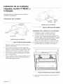
Appliance Installation Assembly of the Transition:
,_ CAUTION:
Vent unit to the outside of building only.
The hood can be mounted on a wall or suspended from a
cabinet. Both vertical and horizontal discharge are possible
with either mounting method.
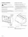
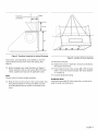
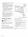
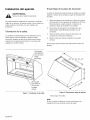
Discharge Direction
The hood is shipped ready for vertical discharge. To
change to horizontal discharge, move the discharge cover
shown in Figure 1 to the top of the hood. The plate is held
in place by four (4) screws.
The supplied transition mounts to the top or rear of the
hood depending on the discharge direction.
1. Align mounting holes at base of transition with
mounting holes on 1/2" flange located at the top or rear
of the hood, depending on direction of discharge.
2. Fasten transition to hood using two (2) # 8 sheet metal
screws (included with hood).
3. Seal connection between transition and hood with duct
tape.
4. Remove tape holding damper closed.
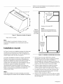
See Figure 2 for overall hood dimensions.
This opening
is covered for
horizontal
discharge
This opening
is covered
for vertical
discharge
Figure 1: Discharge Direction
Figure2: Overall Dimensions
* Varies by model.
Note:
Read Remote Control Installation Instructions before
continuing if using this accessory.
English 4

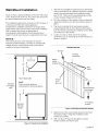
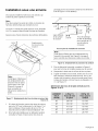
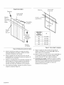
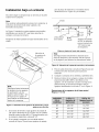
Wall Mount Installation
Figure 3 shows a typical installation of the hood with a duct
cover. Accessory 6" and/or 12" duct covers are used to fill
the space between the hood and ceiling.
The installation height shown in Figure 3 is 36"; however, it
is necessary to follow the cooking appliance
manufacturer's installation instructions for proper hood
height. One 6" duct cover has been used in this installation.
Add or subtract duct covers as appropriate to
accommodate ceiling height and recommended hood
height. The duct cover structure is supported by the hood.
NOTICE:
The hood could incur some damage from heat if a
Professional Series Range or Cooktop is operated with
multiple burners at high settings under a hood that is
installed at minimum clearances.
1. After the hood installation height has been determined,
draw a horizontal line at a distance above the cooktop
equal to the recommended hood installation height
plus 15-1/2". This line is the mounting location of the
wooden bracket shipped with the hood.
2. Find the centerline of the cooktop. Draw a vertical line
along this centerline up to the horizontal line drawn in
Step 1.
3. The hood is mounted to the wall using a wooden
bracket shipped with the hood. Remove the bracket
from the hood by removing two shipping screws. Mark
the center line of the bracket.
,
Locate one stud on either side of the cooktop
centerline to use for mounting the wooden bracket as
shown in Figure 4.
Wooden Bracket
Standard
8 ft Ceiling
(96")
24" TD C°v_ I_
f
Hood Height (36")
NOTE:
Follow cooking appliance
manufacturer's recommendations.
1
Standard
36" high
Range
Figure 3: Typical Hood Installation
Drywall
Height
Above ,
Cooktop °_
Screws
(2 ea
#14 x 3")
Cooktop
Centerline
To Cooktop
Surface
Figure 4: Mounting the Wooden Bracket
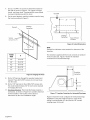
5. Align the top of the wood bracket along the horizontal
line drawn in Step 1. Align the centerlines of the
bracket and cooktop.
6. Drill a 3" deep 1/8" tap hole through the wooden
bracket, drywall, and into the stud.
English 5

7. Use2or3(#14x3")screwstoattachthebracketto
thewallasshowninFigure4.Forsupportoflonger
hoods,usethreestuds.Countersinkthescrewheads
topreventinterferencewiththehood.
8. Onthewoodbracket,markthelocationsusedtohang
thehoodaccordingtoFigure5.
Drywall
Cooktop
% Centerline
I
!
|
Screws
(2 ea.#14 x 3")
HOOD
A
SIZE
30" 13-1/16"
36" 16-1/16"
42" 19-1/16"
48" 22-1/16"
54" 25-1/16"
A measurement
|
i
I
Figure 5: Hanging the Hood
9. Drill a 1/8" tap hole through the wooden bracket and
drywall. These (# 8 x 5/8") screws do not need to go
into the studs.
10. Drill a 1/16" tap hole for the 2 (#8 x 5/8") screws into
the wood bracket leaving 1/4" of each screw exposed
for hanging the hood.
11. Discharqe Direction: Horizontal discharge requires a
wall cutout, as shown in Figure 6, to provide clearance
for the transition. The location of the cutout is
determined by the hood installation height.
23 iJ
÷
12-1/2"
1
t T--
Cooktop _
Centerline
Baseof Hood
Location
Figure 6: Cutout Dimensions
Note:
Dashed line indicates cutout needed for clearance of the
transition.
The transition supplied with the hood connects to standard
10-inch round duct. Figure 7 shows the transition
connected for horizontal discharge.
10-1/4"
Transition
Centerline
0-1/2"
Figure 7: Transition Centerline for Horizontal Discharge
Figure 8 shows the hood configured for vertical discharge.
Installations using this method require a cutout in the
ceiling to accommodate 10" duct and the 1/2" conduit
carrying power to the unit.
English 6

Transition
Centerline
I
15-13/16"
I
Wall
m
10-1/4"
18"
Figure 8: Transition Centerline for Vertical Discharge
Duct covers, sold separately, are available to cover the
space between the top of the hood and ceiling. (See
page 3.)
12. Before hanging hood, install transition per Figure 7.
Fasten transition with two (2) screws (#8 x 3/8 sheet
metal, supplied) and tape per all applicable codes.
Note:
Screws must not hinder damper operation.
13. Rest the hood on the screws in the wood bracket. Use
the keyholes labeled "1"in Figure 9. Make sure the
wood bracket fits into the recess on the back of the
hood.
Figure 9: Location of Screw Keyholes
14. Remove knockouts.
15. Tighten the screws in keyholes. Check hood levelness
and adjust if necessary.
16. From inside the hood, drive screws (#8 x 5/8") through
holes in hood into wooden bracket. See holes labeled
"J" in Figure 9.
17. Connect additional ducting.
Installation Note:
If wall studs are within 8" of the center line, cut stud at an
angle to avoid any interference.
English 7

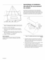
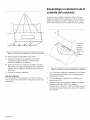
Assembly and Installation of
the Duct Covers
Optional duct covers shown in Figure 10 may be used to fill
the space between the hood and ceiling in wall mount
installations. 6" and 12" high duct covers are available and
may be ordered separately.
#8 x 3/8"
screw
(quantity
dependent
on screw
size)
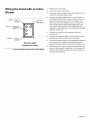
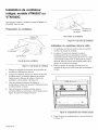
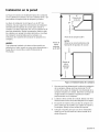
Cabinet Installation
The hood can be installed under a cabinet by supporting
the hood from the top.
Note:
The cabinet must be structurally joined to the wall studs to
support the weight of this hood.
Figure 11 shows the four (4) screw holes labeled "K" used
for mounting the hood to the bottom of the cabinet.
Make sure both knockouts have been removed.
K
1
"-- Tap Hole Locations
,
Figure 10: Attachment of Duct Cover(s) to Hood
If multiple duct covers are used, connect the pieces
together using sheet metal screws provided with the
duct cover accessories.
2. Attach the duct cover(s) to the hood using sheet metal
screws as shown in Figure 10.
3. From inside of hood, insert screws supplied (#8 x 5/8")
through holes labeled "L," one (1)on each side and
four (4) along the front, into bottom of the cover.
Note:
This figure depicts
tap hole and screw
hole locations only.
See Figure 2 on
page 4, for overall
hood dimensions.
Figure 11: Tap Hole and Screw Hole Locations
1. In the base of the cabinet, drill 1/8" tap holes (See
Dimension A in Figure 11 and in Table). Screw in
four (4) #10 x 1" screws (provided with hood) leaving
1/4" exposed.
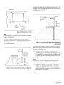
2. If the hood is installed for vertical discharge, use
Figure 12 to create clearance holes for passage of the
transition and conduit (See Dimension B in Figure 12
and in the Table.)
English 8

Wall
J
_8"
._ _..-'" __ 2-3/8" / T
C:°_r_n e _1 5/8" DIA cl£rance
3-3/16"
holes for 1/2" conduit
to j-box.
Plan View of Cabinet Cutout
Note:
This figure depicts transition and conduit
locations only. See Figure 2 on page 4 for overall
hood dimensions.
Figure 12: Transition and Conduit Locations
3. For horizontal discharge, use Figure 6 for the geometry
of the cutout required for clearance of the transition.
4. Hang hood from screws and tighten securely.
5. From inside of hood, insert screws supplied. Drill
through holes (use #8 x 5/8" screws supplied), one (1)
on each side and four along the front, into bottom of the
cabinet. See screw holes labeled "L" in Figure 11.
Centerline Hole Dimensions for Figures 11 and 12
30" 29-1/16" 13-7/16"
36" 35-1/16" 16-7/16"
42" 41-1/16" 19-7/16"
48" 47-1/16" 22-7/16"
54" 53-1/16" 25-7/16"
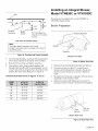
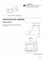
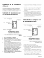
Installing an Integral Blower,
Model VTN630C or VTN1030C
The hood can be installed with a model VTN630C or
VTN1030C integral blower.
Blower Preparation
;_Brackets
Wire tie
Capacitor
Blower Front View
,
2.
Figure 13: Blower Front View
Remove left and right shipping brackets and discard.
Cut wire tie shown in Figure 13. Locate the wire
harness with the Molex 6-pin connector. Route wire
harness out rear of blower, as shown in Figure 14
below.
3. Re-attach wire harnesses to capacitor with new wire tie
(supplied) in same location in front.
4. Attach wire harness with Molex 6-pin connector to
housing as shown in Figure 14 with wire tie (supplied).
\
\
© \
Wire
Harness
Blower Rear View
Add wire
tie here
Figure 14: Blower Rear View
English 9

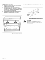
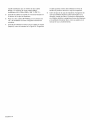
Install Blower in Hood
1. The blower is attached to the hood using weld studs
provided on the mounting plate.
2. Figure 15 shows the weld studs in location B for
horizontal (rear) discharge. Attach four (4) #10-24 nuts
to the weld studs. For vertical discharge, attach nuts to
studs at the top of the mounting plate.
3. Guide the motor mounting plate over the studs and
tighten nuts to secure the blower to the hood.
j" "\
B\.C] .B
4. Attach two (2) additional screws as shown in Figure 16.
Ventillator
Assembly
Additional _&
Screws
Figure 16: Attachment of Additional Screws
CAUTION"
Verify that the two (2) additional screws in
Figure 16 are installed and properly tightened
before continuing.
Figure 15: Weld Stud Locations
English 10

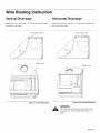
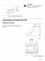
Wire Routing Instruction
Vertical Discharge Horizontal Discharge
Install wire cover per Figure 17. The 30" wide model does
not need a wire cover.
Install wire cover per Figure 18. The 30"-wide model does
not need a wire cover.
Route wires here Route wires here
Wire Cover
Wire Cover
Figure 17: Vertical Discharge
Figure 18: Horizontal Discharge
WARNING:
Turn off electricity at the service panel before
wiring the unit. (See "Safety Instructions" on
page 1.)
English 11

Wiring the Hood with an
Integral Blower
1. Integral Blower models VTN630C and VTN1030C are
designed to work with the PH hoods and are sold
separately.
2. Remove the j-box cover.
3. Connect the blower's Molex plug connector to the
connector present inside the hood as shown in
Figure 19.
4. Install 1/2" conduit connector in j-box.
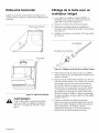
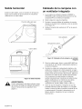
Wiring the Hood with a
Remote Blower
RED--LOW
SPEED
WHITE--
NEUTRAL
BLUE--MEDIUM 0
SPEED
From
From Control Pan_
Figure 19: Wiring the Hood with an Integral Blower
5. Run black, white, and green wires (#12 AWG) in 1/2"
conduit from power supply to J-box.
6. Connect the power supply wires to the hood wires in
the following order: black to black, white to white, and
green wire to green ground screw on chassis. Use
spring type wire nuts supplied. (Lost or missing wire
nuts should only be replaced with: Spring type wire
nuts rated for a minimum of two (2) # 18ga wires and
maximum of four (4) #14ga wires, UL & CSA rated to
600V and 302° F./150° C.)
7. Close J-box cover. Check to see that light bulbs are
secure in their sockets. Replace filters as described in
the Care & Use Manual. Turn power on at service
panel. Check operation of the hood.
Remote Blower Installation
,
2.
3.
BLACK- HIGH
SPEED
PIG TAIL ASM
(included w/hood)
Figure 20: Wiring the Hood with a Remote Blower
Remove the J-box cover.
Install 1/2" conduit connectors.
Run black, white, and green wires (#12 AWG) in 1/2"
conduit from power supply to j-box.
4. Connect the power supply wires to the hood wires in
the following order: black to black, white to white, and
green wire to green ground screw on chassis. Use
spring type wire nuts supplied. (Lost or missing wire
nuts should only be replaced with: Spring type wire
nuts, rated for a minimum of (2) # 18ga wires and
maximum of (4) #14ga wires, UL & CSA rated to 600V
and 302 ° F./150° C).
5. Connect the "pigtail" to the connector inside the
junction box.
6. Run five (5) wires (#14 AWG) in 1/2" conduit from the
remote blower to the second conduit connector.
7.
,
Connect the remote ventilator to the pigtail wires (Step
6) as per Figure 20. Connect the remote blower green
(ground) wire to the ground screw in the junction box.
Close junction box cover. Check that all light bulbs are
secure in their sockets. Install filters. Turn power on at
service panel, and check lights and blower operation
per Care & Use Manual.
The PH hood models are designed to work with VTR630D,
VTR1030D, or VTR1330E remote blowers. For installation
instructions see the instructions supplied with the blower
unit.
English 12

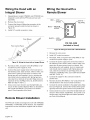
Wiring the Hood with an Inline
Blower
RED -- LOW WHITE --
SPEED NEUTRAL
BLUE -- MEDIUM
SPEED
BLACK -- HIGH
SPEED
PIG TAIL ASM
(included w/hood)
Figure 21 :Wiring the Hood with an Inline Blower
,
2.
3.
Remove the J-box cover.
Install 1/2" conduit connectors.
Run black, white, and green wires (#12 AWG) in 1/2"
conduit from power supply to j-box.
4. Connect the power supply wires to the hood wires in
the following order: black to black, white to white, and
green wire to green ground screw on chassis. Use
spring type wire nuts supplied. (Lost or missing wire
nuts should only be replaced with: Spring type wire
nuts, rated for a minimum of (2) # 18ga wires and
maximum of (4) #14ga wires, UL & CSA rated to 600V
and 302 ° F./150° C).
5. Connect the "pigtail" to the connector inside the
junction box.
6. Run five (5) wires (#14 AWG) in 1/2" conduit from the
inline blower to the second conduit connector.
7.
,
Connect the inline ventilator to the pigtail wires (Step 6)
as per Figure 21. Connect the inline blower green
(ground) wire to the ground screw in the junction box.
Close junction box cover. Check that all light bulbs are
secure in their sockets. Install filters. Turn power on at
service panel, and check lights and blower operation
per Care & Use Manual.
English 13
Page is loading ...
Page is loading ...
Page is loading ...
Page is loading ...
Page is loading ...
Page is loading ...
Page is loading ...
Page is loading ...
Page is loading ...
Page is loading ...
Page is loading ...
Page is loading ...
Page is loading ...
Page is loading ...
Page is loading ...
Page is loading ...
Page is loading ...
Page is loading ...
Page is loading ...
Page is loading ...
Page is loading ...
Page is loading ...
Page is loading ...
Page is loading ...
Page is loading ...
Page is loading ...
Page is loading ...
Page is loading ...
Page is loading ...

Consultwithaqualifiedheatingandventilationspecialistforyourspecific
ventilationrequirements.
Wereservetherighttochangespecificationsordesignwithoutnotice.Some
modelsarecertifiedforuseinCanada.Thermadorisnotresponsibleforproducts
whicharetransportedfromtheU.S.foruseinCanada.Checkwithyourlocal
Canadiandistributorordealer.
Forthemostuptodatecriticaldimensionsbyfax,useyourfaxhandsetandcall
775-833-3600.Usecode#8030.
Consultezunsp6cialistequalifi6enchauffageetenventilationpourconnattreles
exigencesdeventilationparticuli_resquis'appliquentAvotrecas.
Nousnousr6servonsledroitdechangerlessp6cificationsoulaconceptionde
nosappareilssanspr6avis.Certainsmodulessontcertifi6spouruneutilisationau
Canada.Thermadorn'estpasresponsabledesproduitstransport6sApartirdes
t_tats-Unis pour une utilisation au Canada. Informez-vous aupr_s de votre
distributeur ou d6taillant local (Canada).
Pour obtenir par t616copieur les dimensions mises Ajour, utilisez le combin6 de
votre t616copieur et entrez le code #8030.
Consulte a un especialista cualificado en calefacci6n y ventilaci6n para conocer
las exigencias particulares de ventilaci6n que se aplican a su caso.
Nos reservamos el derecho de cambiar las especificaciones o la concepci6n de
nuestros aparatos sin notificaci6n. Algunos modelos estAn aprobados para un
uso en CanadA. Thermador no es responsable de los productos transportados
desde Estados Unidos para un uso en CanadA. Inf6rmese con su distribuidor o
minorista local (CanadA).
Para obtener por fax las dimensiones actualizadas, Ilame al 775-833-3600 con su
fax y marque el c6digo #8030.
5551 McFadden Avenue, Huntington Beach, CA 92649 • 800-735-4328 • www.thermador.com
9000559090 • Rev. A • 5U035E • 05/10 © BSH Home Appliances Corporation, 2010 • All rights reserved
Litho in USA
-
 1
1
-
 2
2
-
 3
3
-
 4
4
-
 5
5
-
 6
6
-
 7
7
-
 8
8
-
 9
9
-
 10
10
-
 11
11
-
 12
12
-
 13
13
-
 14
14
-
 15
15
-
 16
16
-
 17
17
-
 18
18
-
 19
19
-
 20
20
-
 21
21
-
 22
22
-
 23
23
-
 24
24
-
 25
25
-
 26
26
-
 27
27
-
 28
28
-
 29
29
-
 30
30
-
 31
31
-
 32
32
-
 33
33
-
 34
34
-
 35
35
-
 36
36
-
 37
37
-
 38
38
-
 39
39
-
 40
40
-
 41
41
-
 42
42
-
 43
43
-
 44
44
-
 45
45


Thermador PH48CS/02 Installation guide
- Type
- Installation guide
Ask a question and I''ll find the answer in the document
Finding information in a document is now easier with AI
in other languages
- français: Thermador PH48CS/02 Guide d'installation
- español: Thermador PH48CS/02 Guía de instalación
Related papers
-
Thermador PH54CS/01 Installation guide
-
Thermador PH54GS User manual
-
-
-
-
-
-
-
-
Thermador VCIN36GWS Installation guide
Other documents
-
Dacor ILb10 User manual
-
Bosch DUH30152UC/01 Installation guide
-
Electrolux PLHV42P8CC Operating instructions
-
-
GE PVW7361EJ1ES Installation guide
-
Jenn-Air UTX2030AAB User manual
-
Sears 233.52159 User manual
-
 Commercial Electric 5302 Installation guide
-
Heartland 3415 User manual
-
Broan AP130SS Owner's manual
