
P
P
P
4
4
4
T
T
T
D
D
D
H
H
H
i
FCC Statement and Copyright
This equipment has been tested and found to comply with the limits of a
Class B digital device, pursuant to Part 15 of the FCC Rules. These limits
are designed to provide reasonable protection against harmful interference
in a residential installation. This equipment generates, uses and can
radiate radio frequency energy and, if not installed and used in
accordance with the instructions, may cause harmful interference to radio
communications. There is no guarantee that interference will not occur in a
particular installation.
The vendor makes no representations or warranties with respect to the
contents here of and specially disclaims any implied warranties of
merchantability or fitness for any purpose. Further the vendor reserves the
right to revise this publication and to make changes to the contents here of
without obligation to notify any party beforehand.
Duplication of this publication, in part or in whole is not allowed without
first obtaining the vendor’s approval in writing.
The content of this user’s is subject to be changed without notice and we
will not be responsible for any mistakes found in this user’s manual. All the
brand and product names are trademarks of their respective companies.

C
C
C
o
o
o
n
n
n
t
t
t
e
e
e
n
n
n
t
t
t
s
s
s
ii
ENGLISH..................................................................................................... 1
P4TDH Features..................................................................................................................1
Package contents................................................................................................................2
Layout of P4TDH .................................................................................................................2
CPU Installation................................................................................................................... 3
DDR DIMM Modules: DDR1-3............................................................................................. 4
Jumpers, Headers, Connectors & Slots .............................................................................. 5
ESPAÑOL ..................................................................................................11
Características del P4TDH ................................................................................................ 11
Contenido del Paquete ...................................................................................................... 12
Disposición del P4TDH...................................................................................................... 12
Instalación de la CPU........................................................................................................ 13
Módulos DDR DIMM: DDR1-3........................................................................................... 14
Conectores, Cabezales, Puentes y Ranuras..................................................................... 15
DEUTSCH ................................................................................................. 21
Merkmale des P4TDH ....................................................................................................... 21
Packungsinhalt ..................................................................................................................22
Layout des P4TDH ............................................................................................................ 22
Installation der CPU........................................................................................................... 23
DDR-DIMM-Module: DDR1-3 ............................................................................................ 24
Jumper, Header, Anschlüsse & Slots................................................................................. 25
日本語........................................................................................................ 31
P4TDH の機能 ................................................................................................................... 31
パッケージ内容...................................................................................................................... 32
P4TDH のレイアウト ........................................................................................................ 32
CPU のインストール............................................................................................................... 33
DDR DIMM モジュール:DDR1-3..................................................................................... 34
ジャンパー、ヘッダー、コネクタ、スロット ............................................... 35
WARPSPEEDER ...................................................................................... 41
Introduction........................................................................................................................ 41
System Requirement ......................................................................................................... 42
Installation ......................................................................................................................... 42
Usage ................................................................................................................................ 44
Page is loading ...

1
English
P4TDH Features
Use Intel 82845G/ 82801DB Chipset, Winbond W83627HF, LAN Chip
(optional), Serials ATA Controller (optional), IEEE 1394 chip (optional) and
H/W sound chip CMI 8738 (optional).
Contains on board I/O facilities, which include a serial port, a parallel port, a
VGA port, a PS/2 mouse port, a PS/2 keyboard port, audio ports, USB
ports, a LAN port (optional), two USB in the game ports (optional) and a
game port.
Supports the Intel Pentium 4
®
(Socket 478) processor up to 2.53 GHz.
Supports Ultra 100/66/33, BMIDE and PIO modes.
Supports USB2.0 High Speed Device.
Supports up to three single-sided or two double-sided * 8 for DDR 200/266
MHz unregister (Non-ECC) devices, running at 400/533 MHz Front Side
Bus frequency.
Does not support double-side x 16 DDR devices.
Supports AGP 2.0 interface, 2X/4X Fast write protocol. (1.5V Only)
Complies with PC ATX form factor specifications.
Supports popular operating systems such as Windows 98SE, Windows NT,
Windows 2000, Windows ME, Windows XP, LINUX and SCO UNIX.
Intel
®
AC’97 2.2 compatible (optional).
High S/N ratio meets PC 99 requirements.
6CH DAC, applicable for leading motherboard chipsets.
Line-in phonejack share with rear out.
Micro phone-jack share with Bas and Center.

2
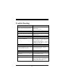
Package contents
HDD Cable X 1, FDD Cable X 1
Flash Memory Writer for BIOS update X 1
USB Cable X 2 (Optional)
Rear I/O Panel for ATX Case X 1 (Optional)
Fully Setup Driver CD X 1
IEEE 1394 Cable X 1 (Optional)
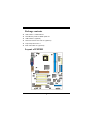
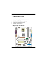
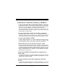
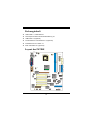
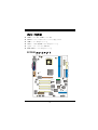
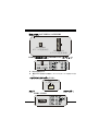
Layout of P4TDH
JKBMS1
JPRNT1
JGAME_USB1
K/B
&
Mouse
JRJ45USB1
USB
&
LAN (Optional)
DDR1
DDR2
LAN
CHIP
(Optional)
JCOM1
JVGA1
COM1
JCFAN1
Parallel Port
INTEL
82845G
COM1
Socket 478
DDR1
DDR2
DDR1
DDR3
CMI8738
AGP1
PCI1
PCI2
PCI3
PCI4
PCI5
CNR1
WOL1
JUSB3
FDD1
IDE1
IDE2
JATXPWR1
JATXPWR2
GAME Port
SP-OUTMIC-IN
LINE-IN
Serials
ATA
Controller
VGA1
JSFAN1
JUSB4
JPANEL1
IDE3
JSATA2JSATA1
JUSBV3_4
JUSBV2
JUSBV1
JKBV1
JCDIN1
JAUDIO1
CODEC
INTEL
82801DB
(ICH4)
FWH
BIOS
JDIMMVOLT
JCMOS1
BAT1
JMS1
JSD1
JSC1
Winbond
I/O
IEEE
J1394B1
J1394A1
J1394C1

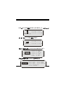
3
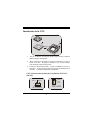
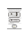
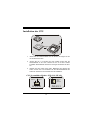
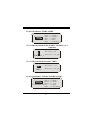
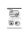
CPU Installation
1. Pull the lever sideways away from the socket then raise the lever up
to 90-degree angle.
2. Locate Pin A in the socket and lock for the white dot or cut edge in
the CPU. Match Pin A with the white dot/cut edge then insert the
CPU.
3. Press the lever down. Then Put the fan on the CPU and buckle it
and put the fan’s power port into the JCFAN1, then to complete the
installation.
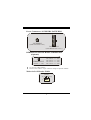
CPU/ System Fan Headers: JCFAN1/ JSFAN1
C
P
U
JCFAN1
1
Ground
12V
Sense
JSFAN1
Ground
12V
Sense
1

4
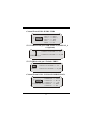
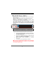
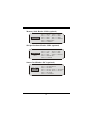
DDR DIMM Modules: DDR1-3
DRAM Access Time: 2.5V Unregister (Non-ECC) DDR 200/266 MHz
Type required.
DRAM Type: 64MB/ 128MB/ 256MB/ 512MB DIMM Module (184 pin)
Due to the limitation of chipset, this board only can support up to 2 banks
of DDR memory.
However, in the market, there are so many single-sided modules
occuping half bank. BIOSTAR would like to utilize the modules as many
as possible. So we divide one bank into 2 sockets. That means the bank
just can support one double-sided or two single-sided modules only.
The Bank 1, contain 2 DDR sockets, one blue & one white.
※ If you have one DDR module and you are not sure if it is a
single or double- sided DDR module, please insert in DDR1
(blue color) socket first.
※ If you have two DDR modules and you are not sure if they are
single or double-sided DDR modules, please insert in DDR1
and 2 (blue color) Sockets.
※ DDR 3, white color sockets, only support single-sided DDR
module.
※ Supports up to two double-sided*8 on DDR1/2.
; For better compatibility, before insert DDR modules into the
sockets, we strongly suggest to use the same type of modules
including the model, speed and size of memory.
Does not support Double-sided * 16 DDR Dimms
Bank 1
DDR1
DDR2
DDR3

5
Jumpers, Headers, Connectors & Slots
Hard Disk Connectors: IDE1/ IDE2/ (IDE3=>optional)
The motherboard has a 32-bit Enhanced PCI IDE Controller that
provides PIO Mode 0~4, Bus Master, and Ultra DMA / 33/ 66/ 100
functionality. It has three HDD connectors IDE1 (primary), IDE2
(secondary) and IDE3 (optional).
The IDE connectors can connect a master and a slave drive, so you can
connect up to four hard disk drives. The first hard drive should always be
connected to IDE1.
Serial ATA Connector: (JSATA1/ JSATA2=>optional)
The motherboard has a PCI to SATA Controller with 2 channels S-ATA
interface, it satisfy the SATA 1.0 spec and can transfer data up to
1.5GHz speed.
Floppy Disk Connector: FDD1
The motherboard provides a standard floppy disk connector that
supports 360K, 720K, 1.2M, 1.44M and 2.88M floppy disk types. This
connector supports the provided floppy drive ribbon cables.
Accelerated Graphics Port Slot: AGP1
Your monitor will attach directly to that video card. This motherboard
supports video cards for PCI slots, but it is also equipped with an
Accelerated Graphics Port (AGP/ only 1.5V and 4X AGP card can be
supported). An AGP card will take advantage of AGP technology for
improved video efficiency and performance, especially with 3D graphics.
Communication Network Riser Slot: CNR1
The CNR specification is an open Industry Standard Architecture, and it
defines a hardware scalable riser card interface, which supports audio,
network and modem only.
Peripheral Component Interconnect Slots: PCI1-5
This motherboard is equipped with 5 standard PCI slots. PCI stands for
Peripheral Component Interconnect, and it is a bus standard for
expansion cards, which has, supplanted the older ISA bus standard in
most ports. This PCI slot is designated as 32 bits.

6
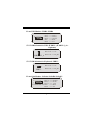
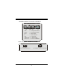
Power Connectors: JATXPWR1/ JATXPWR2
DIMM Power Selection Header: JDIMMVOLT
(Optional)
z It is for over voltage function.
z Please set this header as “Open” while the voltage are adjusted via BIOS.
Wake On LAN Header: WOL1
WOL1
1
5V_SB Wake up
Ground
JATXPWR1
(ATX Main Power Conn.)
JATXPWR2
(ATX 12V Power Conn.)
1
2
JDIMMVOLT
Pin 1-2 off ==> 2.6V
Pin 3-4 off ==> 2.7V
Pin 5-6 off ==> 2.8V
Pin 7-8 off ==> 2.9V
(Default ==> 2.5V)
1
2
JDIMMVOLT
Jump open ==> 2.5V
Pin 1-2 on ==> 2.6V
Pin 3-4 on ==> 2.7V
Pin 5-6 on ==> 2.8V
Pin 7-8 on ==> 2.9V
(Default ==> 2.6V)

7
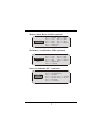
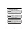
Front USB Header: JUSB3/ JUSB4
5V/ 5VSB Selection for USB: JUSBV1/ (JUSBV2/3_4=>
Optional)
5V/ 5VSB Selection for Keyboard: JKBV1
Front 1394 Header: J1394A1/J1394B1/J1394C1
JUSB3/4
2
1
Pin1,2 ==> +5V
Pin3,4 ==> Data(-)
Pin5,6 ==> Data(+)
Pin7,8 ==> Ground
Pin9 ==> KEY
Pin10 ==> NA
1
JKBV1
Pin 1-2 on ==> 5V
Pin 2-3 on ==> 5V_SB
1
JUSBV1/2/3_4
Pin 1-2 on ==> 5V
Pin 2-3 on ==> 5V_SB
J1394A1/B1/C1
2
1
Pin1,2 ==> A+/A-
Pin3,4 ==> Ground
Pin5,6 ==> B+/ B-
Pin7,8 ==> +12V
Pin9 ==> KEY
Pin10 ==> NA

8
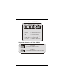
Memory Stick Header: JMS1 (optional)
SD Memory Card Header: JSD1 (optional)
Smart Card Header: JSC1 (optional)
JMS1
Pin1 ==> Ground , Pin2 ==> MS1
Pin3 ==> 3.3V , Pin4 ==> MS2
Pin5 ==> MS3 , Pin6 ==> MS4
Pin7 ==> MS5 , Pin8 ==> MSCLK
Pin9 ==> MSPWCTL#
Pin10 ==> MSLED
1
JSD1
Pin1 ==> Ground , Pin2 ==> SD1
Pin3 ==> 3.3V , Pin4 ==> SD2
Pin5 ==> SD3 , Pin6 ==> SD4
Pin7 ==> S 5 , Pin8 ==> SDCLK
Pin9 ==> SDPWCTL#
Pin10 ==> SDLED
D
1
JSC1
Pin1 ==> 5V , Pin2 ==> Ground
Pin3 ==> SCAPWRCTL#
Pin4 ==> SCAR5#
Pin5 ==> SCAC4 , Pin6 ==> SCALED
Pin7 ==> SCAIO , Pin8 ==> SCAC8
Pin9 ==> SCACLK
Pin10 ==> SCAPSNT
1
2

9
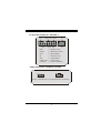
Front Panel Connector: JPANEL1
Audio Subsystem: JAUDIO1/ JCDIN1
SPK
PWR_LED
HLED
SLP
RST
2
24
IR
1
23
IRON/OFF
SPK ==> Speaker Conn.
HLED ==> Hard Driver LED
RST ==> Reset Button
IR ==> Infrared Conn.
SLP ==> Sleep Button
PWR_LED ==> Power LED
ON/ OFF ==> Power-on Button
1
2
JAUDIO1
(Front Audio Header)
1
JCDIN1
(CD-ROM Audio-In Header)

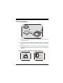
10
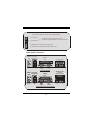
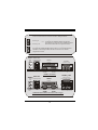
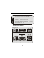
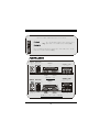
Back Panel Connectors
PS/2
Keyboard
PS/2
Mouse
COM1
Parallel
Game Port/
USB Ports (optional)
JPRNT1
JGAME1_USB1
JCOM1
JKBMS1
USB
LAN(Optional)
RJ45USB1
COM1
Speaker
Out
Line In
Mic
In
JVGA1
VGA1
PS/2
Keyboard
PS/2
Mouse
COM1
Parallel
Game Port/
USB Ports (optional)
JPRNT1
JGAME1_USB1
JCOM1
JKBMS1
USB
LAN(Optional)
RJ45USB1
COM1
Speaker
Out
Line In
Mic
In
JVGA1
VGA1
PS/2
Keyboard
PS/2
Mouse
COM1
Parallel
Game Port
JPRNT1
JGAME1_USB1
JCOM1
JKBMS1
USB
LAN(Optional)
RJ45USB1
COM1
Speaker
Out
Line In
Mic
In
JVGA1
VGA1
(Normal Mode)
(Add USB Game Port Mode)
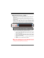
12
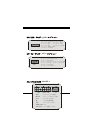
Front Panel Audio Connector/ Jumper Block
910
Audio line out signals are routed
to the back panel audio line out connector.
Pin 5 and 6
==>
Pin 9 and 10
12
9
10
Audio line out and mic in signals are
available for front panel audio connectors.
Page is loading ...
Page is loading ...
Page is loading ...
Page is loading ...
Page is loading ...
Page is loading ...
Page is loading ...
Page is loading ...
Page is loading ...
Page is loading ...
Page is loading ...

22
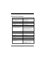
Packungsinhalt
HDD-Kabel X 1, FDD-Kabel X 1
Flash-Speicher-Writer für BIOS-Aktualisierung X 1
USB-Kabel X 2 (Optional)
I/O-Rückseite für ATX-Gehäuse X 1 (Optional)
Installations-CD für Treiber X 1
IEEE 1394-Kabel X 1 (Optional)
Layout des P4TDH
JKBMS1
JPRNT1
JGAME_USB1
K/B &
Maus
JRJ45USB1
USB
&
LAN (Optional)
D
D
R
1
D
D
R
2
LAN
CHIP
(Optional)
JCOM1
JVGA1
C
O
M
1
JCFAN1
P
a
r
a
l
l
e
l
e
S
c
h
n
i
t
t
s
t
e
l
l
e
INTEL
82845G
C
O
M
1
Sockel 478
D
D
R
1
D
D
R
2
D
D
R
1
D
D
R
3
CMI8738
AGP1
PCI1
PCI2
PCI3
PCI4
PCI5
CNR1
WOL1
JUSB3
FDD1
IDE1
IDE2
JATXPWR1
JATXPWR2
G
a
m
e
p
o
r
t
S
P
-
O
U
T
L
I
N
E
-
I
N
Serieller
ATA
Controller
V
G
A
1
JSFAN1
JUSB4
JPANEL1
IDE3
JSATA2JSATA1
JUSBV3_4
JUSBV2
JUSBV1
JKBV1
JCDIN1
JAUDIO1
CODEC
INTEL
82801DB
(ICH4)
FWH
BIOS
JDIMMVOLT
JCMOS1
BAT1
JMS1
JSD1
JSC1
Winbond
I/O
IEEE
J1394B1
J1394A1
J1394C1
JATXPWR2
Page is loading ...
Page is loading ...
Page is loading ...
Page is loading ...
Page is loading ...

28
Memory Stick Header: JMS1 (optional)
SD-Speicherkarte-Header: JSD1 (optional)
Smart Card Header: JSC1 (optional)
JMS1
Pin1 ==> Masse , Pin2 ==> MS1
Pin3 ==> 3.3V , Pin4 ==> MS2
Pin5 ==> MS3 , Pin6 ==> MS4
Pin7 ==> MS5 , Pin8 ==> MSCLK
Pin9 ==> MSPWCTL#
Pin10 ==> MSLED
1
JSD1
Pin1 ==> Masse , Pin2 ==> SD1
Pin3 ==> 3.3V , Pin4 ==> SD2
Pin5 ==> SD3 , Pin6 ==> SD4
Pin7 ==> S 5 , Pin8 ==> SDCLK
Pin9 ==> SDPWCTL#
Pin10 ==> SDLED
D
1
JSC1
Pin1 ==> 5V , Pin2 ==> Masse
Pin3 ==> SCAPWRCTL#
Pin4 ==> SCAR5#
Pin5 ==> SCAC4 , Pin6 ==> SCALED
Pin7 ==> SCAIO , Pin8 ==> SCAC8
Pin9 ==> SCACLK
Pin10 ==> SCAPSNT
1
2
Page is loading ...
Page is loading ...
Page is loading ...
Page is loading ...
Page is loading ...
Page is loading ...
Page is loading ...
Page is loading ...
Page is loading ...
Page is loading ...
Page is loading ...
Page is loading ...

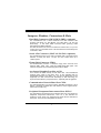
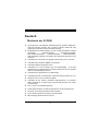
41
WarpSpeeder
Introduction
[ WarpSpeeder™ ], a new powerful control utility, features three user-friendly
functions including Overclock Manager, Overvoltage Manager, and Hardware
Monitor.
With the Overclock Manager, users can easily adjust the frequency they prefer
or they can get the best CPU performance with just one click. The Overvoltage
Manager, on the other hand, helps to power up CPU core voltage and Memory
voltage. The cool Hardware Monitor smartly indicates the temperatures, voltage,
CPU fan speed as well as the chipset information. Also, in the About panel, you
can get the detailed descriptions about BIOS model and chipsets. In addition,
the frequency statuses of CPU, memory, AGP, and PCI along with the CPU
speed are synchronically shown on our main panel.
Moreover, to protect users' computer systems if the setting is not appropriate
when testing and results in system fails or hangs, [ WarpSpeeder™ ]
technology assures the system stability by automatically rebooting the computer
and then restart to a speed that is either the original system speed or a suitable
one.

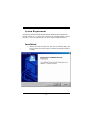
42
System Requirement
OS Support: Windows 98 SE, Windows 98 Me, Windows 2000, Windows XP
DirectX: DirectX 8.1 or above. (The Windows XP operating system includes
DirectX 8.1. If you use Windows XP, you do not need to install DirectX 8.1.)
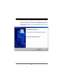
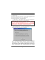
Installation
1. Execute the setup execution file, and then the following dialog will
pop up. Please click “Next” button and follow the default procedure
to install.

43
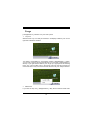
2. When you see the following dialog in setup procedure, it means
setup is completed. If the “Launch the WarpSpeeder Tray Utility”
checkbox is checked, the Tray Icon utility and [ WarpSpeeder™ ]
utility will be automatically and immediately launched after you click
“Finish” button.

44
Usage
[ WarpSpeeder™ ] includes 1 tray icon and 5 panel:
1. Tray Icon:
Whenever the Tray Icon utility is launched, it will display a little tray icon on the
right side of Windows Taskbar.
This utility is responsible for conveniently invoking [ WarpSpeeder™ ] Utility.
You can use mouse to left-click the little tray icon to invoke [ WarpSpeeder™ ]
directly or you right-click the little tray icon to pop up a popup menu as following
figure. The “Launch Utility” item in the popup menu has the same function as
mouse left-click on tray icon and “Exit” item will close Tray Icon utility if selected.
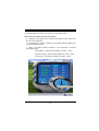
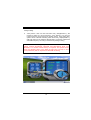
2. Main Panel
If you click the tray icon, [ WarpSpeeder™ ] utility will be invoked. Please refer

45
the following figure; the utility’s first window you see is Main Panel.
Main Panel contains features as follows:
a. Display the CPU Speed, CPU external clock, Memory clock, AGP clock,
and PCI clock information.
b. Contains About, Voltage, Overclock, and Hardware Monitor Buttons for
invoking respective panels.
c. With a user-friendly Status Animation, it can represent 3 overclock
percentage stages:
Man walking => overclock percentage from 100% ~ 110 %
Panther running => overclock percentage from 110% ~ 120%
Car racing => overclock percentage from 120% ~ above

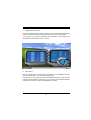
46
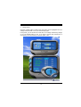
3. Voltage Panel
Click the Voltage button in Main Panel, the button will be highlighted and the
Voltage Panel will slide out to up as the following figure.
In this panel, you can decide to increase CPU core voltage and Memory voltage
or not. The default setting is “No”. If you want to get the best performance of
overclocking, we recommend you click the option “Yes”.
Page is loading ...
Page is loading ...
Page is loading ...
Page is loading ...
Page is loading ...
Page is loading ...
Page is loading ...
Page is loading ...
Page is loading ...
Page is loading ...
Page is loading ...
-
 1
1
-
 2
2
-
 3
3
-
 4
4
-
 5
5
-
 6
6
-
 7
7
-
 8
8
-
 9
9
-
 10
10
-
 11
11
-
 12
12
-
 13
13
-
 14
14
-
 15
15
-
 16
16
-
 17
17
-
 18
18
-
 19
19
-
 20
20
-
 21
21
-
 22
22
-
 23
23
-
 24
24
-
 25
25
-
 26
26
-
 27
27
-
 28
28
-
 29
29
-
 30
30
-
 31
31
-
 32
32
-
 33
33
-
 34
34
-
 35
35
-
 36
36
-
 37
37
-
 38
38
-
 39
39
-
 40
40
-
 41
41
-
 42
42
-
 43
43
-
 44
44
-
 45
45
-
 46
46
-
 47
47
-
 48
48
-
 49
49
-
 50
50
-
 51
51
-
 52
52
-
 53
53
-
 54
54
-
 55
55
-
 56
56
-
 57
57
-
 58
58
-
 59
59
-
 60
60


Ask a question and I''ll find the answer in the document
Finding information in a document is now easier with AI
in other languages
- español: Biostar P4TDH El manual del propietario
- Deutsch: Biostar P4TDH Bedienungsanleitung
- 日本語: Biostar P4TDH 取扱説明書
Related papers
-
Biostar P4M80-M4 Owner's manual
-
-
-
-
-
-
-
-
-
Other documents
-
Mach P4MSD-800 User manual
-
EVGA 141-LF-E658-KR User manual
-
-
-
-
-
-
Gigabyte G-MAX goPC Install Manual
-
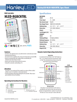 HanleyLED HLED-RGBCNTRL Operating
-
Abit AI7-G User manual
