Page is loading ...

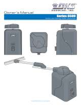
Dual-Channel Loop Detector
DoorKing Part Number
9409-010
This “Self-tuning” loop detector is designed to be used with DoorKing vehicular gate operators ONLY and control two individual
loops (including 2 series wired reversing loops configuration). The loop detector plugs into loop detector ports on the gate operator
control board. This “Self-tuning” detector will constantly monitor the loop’s frequency status and “Self-tune” for any minor devia-
tions with the frequencies to keep the loop operating normally and decrease “false calls”. The detector also employs several
automatic and advanced features that will assist technicians in the field with trouble shooting loop problems.
Refer to the Loop Information Manual located at www.dkaccess.com for information on installing in-ground loops.
120 Glasgow Avenue
Inglewood, California 90301
U.S.A.
LOOP 1
DIP
SW 2
DIP
SW 1
LOOP 2
Switch 1 Switch 2
High
Med-High
Med-Low
Low
OFF
OFF
ON
ON
OFF
ON
OFF
ON
Switch 3 Switch 4
OFF
OFF
ON
ON
OFF
ON
OFF
ON
LOOP 1
Adjust Loop Sensitivity Turn On Sensitivity Boost
Turn On Fast-Trak
LOOP 2 LOOP 1 LOOP 1LOOP 2 LOOP 2
Switch 2 Switch 3
Low
Med-Low
Med-High
High
OFF
OFF
ON
ON
OFF
ON
OFF
ON
Switch 6 Switch 7
OFF
OFF
ON
ON
OFF
ON
OFF
ON
Normal-OFF
Fast-Trak-ON
Normal-OFF
Fast-Trak-ON
Normal-OFF
Boost-ON
Normal-OFF
Boost-ON
Switch 1 Switch 5Switch 4 Switch 8
LOOP 2
SW1
SW2
ON
ON
LOOP 1
Frequency DIP-Switches
When the detector is powered up, or when the reset button is pressed, the detector
will blink out the frequency each loop has tuned to (in KHz), first on L1 and then L2
LEDs. For example, L1 blinks five times - pause - blinks six times then L2 blinks five
times - pause - blinks two times indicates that Loop 1 has tuned to 56 KHz and Loop 2
has tuned to 52 KHz. This automatic frequency measurement is useful in applications
for two or more loops that are in close proximity to each other.
A common problem with
loops are when they are
positioned too close to
each other and their
detection fields
overlap. If the loops are on
similar frequencies, this can
cause “cross-talk” between
the loops and “false calls” can occur in the loop detector(s). Knowing what frequency
each loop has tuned to allows you to adjust the frequencies of each loop. Keep the
frequencies as far apart from each other as possible and the loop with the longest
length of wire should be set to the lowest frequency. Switching the frequency of a loop
WILL NOT affect any of the operation adjustments or the over all detecting height of
the loop.
Frequency
Operation
Adjustments
9409
Operation Adjustments DIP-Switches
Loop Sensitivity
Adjusts how much moving metal must be present in the loop detection field before the loop detector will send an output.
Sensitivity Boost
Once the detector senses a vehicle, this feature increases the loop detector’s sensitivity to compensate for a higher section of that
vehicle (usually a truck trailer or truck bed) that the detector may not completely sense, and allow the vehicle to pass completely
over the loop before closing the gate. This prevents the loop detector from “losing detection” on a higher part of a vehicle and start
the closing cycle before the vehicle has cleared the loop. This feature can be individually turned ON for each loop but WILL NOT
increase a loop’s over all detecting height.
Fast-Trak
Fast-Trak is useful on degraded loops that may drift in frequency over a period of time. An indication of this would be when the
detector has an excessive amount of “false calls”.This is usually caused by poor quality wire in the loop itself, a poor wire connec-
tion in the loop system or wire insulation damage. It usually fails when the loop gets wet but will
work OK when the moisture is gone. When Fast-Trak is turned ON, it will allow the loop’s frequency
to drift more than normal and not give the excessive “false calls”. Caution should be exercised
when using the Fast-Trak feature. If excessive frequency drift continues (indicated by an excessive
amount of “false calls” with Fast-Trak turned ON), the loop itself will have to be replaced. Fast-Trak
can be individually turned ON for each loop.
J1
L2L1

9405-065-G-4-09
DoorKing Part Number
9409-010
Copyright 2009 DoorKing, Inc. All rights reserved.
120 Glasgow Avenue
Inglewood, California 90301
U.S.A.
LOOP 2
SW1
SW2
ON
ON
LOOP 1
Reset Button
Surge Protectors
J1 Jumper
Terminals
9409
Note: If using shielded twisted pair
loop lead-in cable, ground shield
at operator end ONLY. All spliced
connections must be soldered.
Connect to
Loop 1
or
Loop 2
terminal.
PVC Conduit
PVC Conduit
20 VDC
Com
5 VDC
Ground Shield to
Operator Chassis
Ground
Insulated (Floated) Shield
Reverse Loop
Reverse Loop
Loop Lead-In Cable
Reverse Loops
Wired in Series
Loop Lead-In Wires
(6 twists per foot)
Connect to a Gate
Operator Circuit
Board Port
Watertight J-Box
Wires
from
Loop
Shielded Twisted Pair
L2L1
J1
Power LED
Loop 1 Terminal
Connect the loop lead-in wires or cable to terminal. Ground loop lead-in cable to operator chassis ground if used.
Loop 2 Terminal
Connect the loop lead-in wires or cable to terminal. Ground loop lead-in cable to operator chassis ground if used.
Loop 2 Output
The output of loop 2 can activate a form C dry contact relay. Connect Common (C), Normally Closed (NC) or Normally Open (NO) to
the gate operator circuit board as required.
J1 Jumper for Loop 2
J1 jumper is set for Loop 2 to operate in the Presence mode (Normal Operation). Removing this jumper will cause Loop 2 to operate
in the Pulse mode (Relay activates for 250 ms, then drops out. Used for specific applications only.).
Loop 1 always operates in the Presence mode (Normal Operation).
Reset Button
Pressing the reset button clears faults and resets the detector.
Power LED
Illuminates when detector has acceptable power.
L1 LED
Illuminates when loop detector senses a vehicle in Loop 1’s detection field and will also indicate Loop 1’s frequency when the
detector is powered up or when a physical problem exists in the loop itself.
L2 LED
Illuminates when loop detector senses a vehicle in Loop 2’s detection field and will also indicate Loop 2’s frequency when the
detector is powered up or when a physical problem exists in the loop itself.
Loop Monitoring with L1 and L2 LEDs
The loop detector constantly monitors the frequency of the loop to determine if the frequency is too high or too low, or if the loop
system has a physical problem. When this happens, the detector will “Lock On” and the L1 or L2 LED will steadily flash depending
on which loop has the problem. If the frequency of the loop returns to nominal levels, the detector
will resume normal operation but will continue to flash the corresponding LED. A steadily flashing
L1 or L2 LED is an indication that a physical problem exist in the loop system itself and that the
loop will probably have to be replaced. The L1 or L2 LED can be reset by pressing the reset button.
/