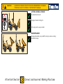
Thwaites Mach 202 Operator's Instruction Manual
- Type
- Operator's Instruction Manual
This manual is also suitable for
Thwaites Mach 202 is a versatile machine designed for a wide range of construction site operations and transportation of bulk materials. Its capabilities include:
- Customary construction site operations
- Transporting bulk site materials
- Towing wheeled loads under controlled conditions
Thwaites Mach 202 is a versatile machine designed for a wide range of construction site operations and transportation of bulk materials. Its capabilities include:
- Customary construction site operations
- Transporting bulk site materials
- Towing wheeled loads under controlled conditions

Mach 202 – Powerswivel Mach 201 – Hi-tip
January 2006: Issue 4
T0489
1 Tonne
Operator’s
Instruction
Manual

DANGER
WARNING CAUTION
Introduction
Safety Symbols
• Attention!
• Become alert!
• Your safety is involved!
• Correct action • Incorrect action/procedure
which should NOT be carried
out
Signal words
Signal words are used on the machine and within this manual to identify levels of hazard seriousness:
Thwaites Limited puts Safety First
It is the policy of Thwaites Limited to promote safety in the
operation of its machines and to create a general awareness of
site safety and safe working practices for the operators of its
machines.
This Operator’s Instruction Manual is intended for both new
and experienced machine operators. It should remain with the
machine at all times. All operators should be aware of its
location and contents.
It is important that all operators are fully trained and familiar
with the machine and that they have read and understood the
information contained within this book before they attempt
to operate in the site conditions for which the machine was
designed.
This book details practices and operations which Thwaites
Limited recommends. DO NOT operate this machine in ways
other than those detailed within this book.
This machine is designed for customary construction site
operations, and the transportation of bulk materials commonly
carried on such sites; that is their ‘intended use’. Under certain
controlled conditions the dumper may be used for towing
wheeled loads.
Due to the varied nature of the operation of site dumpers and
the absence of an agreed test standard, any figures quoted by
Thwaites in relation to vibration values and exposure are for
reference purposes only. It is the responsibility of the
employer to assess vibration exposure based on the actual site
conditions, and operating practices, at the point of use.
Hand Arm Vibration - The daily exposure Action/Limit Values
of between 2.5 - 5.0m/s2 (A8) are unlikely to be exceeded in an
eight-hour reference period.
Whole Body Vibration - The daily exposure can only be
accurately determined at the point of use. This exposure must
be managed in respect of the Action/Limit Values of 0.5 and
1.15 m/s2 (A8) respectively.
Employers should not rely solely on published vibration
figures when undertaking risk assessments. Depending on the
site conditions, cycle times may need to be adjusted in order
to reduce operator exposure levels.
Vibration values based on typical duty cycles are available on
request from Thwaites. These may be used for reference
purposes only.

1
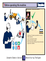
Complet e Checks in Sect ion Before St art ing The Engine
Distributor
Read operator’s instruction manual
Before operating this machine
1. Contact your Thwaites representative in case of
further questions
2. Learn to operate this machine
3. Ensure you are fit to operate
4. Wear correct safety clothing and ensure that safety
equipment is available

1
Complet e Checks in Sect ion Before St art ing The Engine
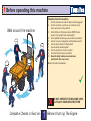
Walk around t he machine
Visually check the machine
1 Are the chassis lock and the skip lock disengaged?
2 Are the controls, crush zone or hydraulic rams
clean, and clear of any debris?
3 Is the Roll-Over Protective frame (ROPS frame)
secure, fully upright and undamaged?
4 Is the seatbelt anchorage secure and serviceable?
5 Are the covers, mudguards and footplate secure?
6 Are the hoses free from fluid leaks?
7 Are all safety decals legible?
8 Are the tyres free of cuts or splits?
9 Are all bolts tight and in position?
10 Have the daily maintenance tasks been
performed? (See rear cover)
Report all faults immediately.
Before operating this machine
DO NOT OPERATE THE MACHINE UNTIL
ALL FAULTS HAVE BEEN RECTIFIED

1
Complet e Checks in Sect ion Before St art ing The Engine
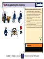
WARNING
Seatbelt MUST BE WORN when operating
machines fitted with a ROPS frame.
Mount the machine and check the controls
1 Use the grabrails and foot steps provided to
manoevre into seating position. Face the machine
at all times when mounting and dismounting
2 Is the engine cover secure and locked?
3 Adjust the seat position for comfort and easy
access to controls
4 Fasten the seatbelt. Adjust accordingly for safety
and comfort
5 Is the emergency stop button in a raised position?
6 Set the transmission to neutral
7 Do not operate the machine without understanding
all its controls as described in the following pages
Before operating this machine

1
Complet e Checks in Sect ion Before St art ing The Engine
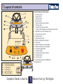
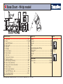
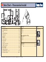
Layout of controls
Control locations & functions
1 Steering wheel
2 Lights switch*
3 Hazard switch*
4 Beacon switch
5 Operator safety guide housing
6 Throttle pedal
7 Tip-skip lever (Hi-Tip model)
Tip-skip and rotate-skip lever (Powerswivel model)
8 Raise-skip lever (Hi-Tip model only)
9 Emergency stop button
10 Direction lamp*
11 Heat/start pilot light
12 Battery charging warning light
13 Horn push
14 Engine oil pressure warning light
15 Water temperature warning light
16 Park brake applied light
17 Full-beam lamp*
18 Circuit breakers (push to reset)
19 Warning buzzer
20 Ignition switch
21 Forward/neutral/reverse (FNR) lever
*Optional features
CB1 Fuel/Direction Solenoids.
CB2 Instrumentation/Warning.
CB3 L/H Sidelights.*
CB4 R/H Sidelights.*
CB5 Ignition Fed Lights.*
CB6 Battery Fed Lights.*

1
Complet e Checks in Sect ion Before St art ing The Engine
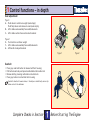
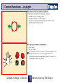
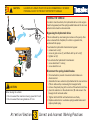
Control functions – in depth
Seatbelt
• Press grey seat belt button to release belt from housing
• Pull belt across body and press buckle blade into buckle lock
• Release belt by pressing red button on buckle lock
• Press grey button to retract belt into housing
Seat belt should not be worn loose, it should pass comfort ably across hip
bones and not t he abdomen
..
..
.
Seat adjustment
Type 1:
A – Push down to set driver weight (seat empty)
Push fully down and release to reset (seat empty)
B – Lift to slide seat assembly forwards/backwards
C – Lift to slide cushion forward and set backrest
Type 2:
E – Turn knob to set driver weight
F – Lift to slide seat assembly forwards/backwards
G – Lift handle to adjust backrest
Type 1 Type 2

1
Complet e Checks in Sect ion Before St art ing The Engine
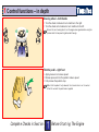
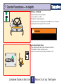
Steering wheel – both hands
• Turn the wheel clockwise to turn machine to the right
• Turn the wheel anti-clockwise to turn machine to the left
Ensure t he non-st eering hand is on t he engine cover grabrail when using t he
spinner knob for low speed single-handed st eering.
Throttle pedal – right foot
• Apply pressure to increase speed
• Release pressure from the pedal to reduce speed
• Fully release the pedal to stop
When t hrot t le pedal is fully released, t he t ransmission is set t o neut ral.
Aft er 2.5 seconds t he park brake is applied.
Control functions – in depth

1
Complet e Checks in Sect ion Before St art ing The Engine
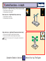
Tip-skip lever - Right Hand (Hi-tip & Powerswivel models)
• Push forward to discharge skip.
• Pull backwards to lower skip.
Raise-skip lever - Right Hand (Hi-tip model only)
• Push forward to raise skip.
• Pull backwards to lower skip.
Skip-rotate lever - right hand (Powerswivel model only)
• Push lever to the right to rotate the skip clockwise
• Push lever to the left to rotate the skip anti-clockwise
Movement of t he skip may slow if t he st eering wheel is moved (priorit y
st eering)
Control functions – in depth

1
Complet e Checks in Sect ion Before St art ing The Engine
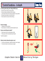
Emergency Stop Button - Right Hand
• Press to apply.
• Pull up to release.
If t he emergency st op but t on is pressed, it will cause t he engine t o st op
running. A warning buzzer and a warning light will be act ivat ed.
The aut omat ic park brake is applied when t he ignit ion is t urned off, or if
t he emergency st op but t on is pressed.
Automatic park brake (both rear wheels)
The park brake is applied in the following conditions:
• the FNR lever is in a neutral position
• the ignition switch is in an ‘off’ position
• the engine is stopped, with emergency stop button pressed
• the throttle pedal is fully released
Control functions – in depth

1
Complet e Checks in Sect ion Before St art ing The Engine
WARNING
Stop machine before changing direction from reverse/
forward and forward/reverse.
FNR lever - left hand
• Push forwards to travel forwards
• Lever centred = neutral
• Pull back to travel backwards
The automatic brake is applied when the FNR lever is in a centred
(neutral) position for longer than 2.5 seconds.
Engine Cover Open/Close
• Insert ignition key and turn anti-clockwise to unlock.
• Pull handle to release and raise cover.
• Lower cover, secure and turn key clockwise to lock.
Control functions – in depth

1
Complet e Checks in Sect ion Before St art ing The Engine
Lowering and raising the folding ROPS frame
• Remove beacon before lowering frame.
• Remove clips and withdraw frame lock pins.
• Lower frame and insert lock pins and clips in new position.
• Reverse the procedure to raise the frame.
• Ensure all pins are secure before driving.
Battery isolator (beneath engine cover)
• Turn key anti-clockwise to isolate the battery power supply.
• Turn key clockwise to activate power supply.
Beacon stowage
• Unplug and remove beacon.
• Secure beacon on bracket provided beneath bonnet.
Beacon switch/hazard switch*
• Push lower switch to activate beacon light.
• Push upper switch to deactivate beacon light.
*optional equipment
Control functions – in depth

2
Complet e Checks in Sect ion Before St art ing The Engine
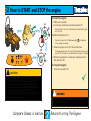
WARNING
DO NOT START THE ENGINE UNLESS SEATED IN
THE DRIVING POSITION.
CAUTION
• Do not use unauthorised starting aids.
• If a panel warning light remains on, switch off
engine (key to ‘O’) and investigate the problem.
• This machine cannot be TOWED or BUMP started
(see section 3 for recovery instructions).
• Do not engage the transmission until the self-test
procedure is complete.
How to START and STOP the engine
To start the engine:
• FNR lever to neutral.
• turn the key clockwise to the start position ‘S’.
All panel light s self-t est (illuminat e) and should ext inguish
on st art -up.
Cold Start Aid (below 0° C) -
Turn key t o posit ion ‘H’. When panel light
ext inguishes
st art engine (as above).
• Allow the engine to turn for 15 seconds max.
If t he engine does not st ar t wit hin 15 seconds ret urn key t o
posit ion ‘O’ and wait 3 0 seconds before t urning t o ‘S’ again.
• When the engine fires, release key. (Springs back to
‘Run' position ‘R’).
To stop the engine:
• Turn key to position ‘O’.

2
Complet e Checks in Sect ion Before St art ing The Engine
CAUTION
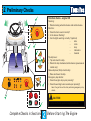
Do not press throttle pedal during these checks.
Preliminary Checks
Function checks - engine ON
Steering:
• Rotate steering wheel clockwise and anti-clockwise.
Electrics:
• Does the horn sound correctly?
• Is the beacon flashing?
• Are the lights working correctly? (optional)
– side
– main
– stop
– indicators
– hazards
Tip-skip lever:
• Tip and return the skip.
• Rotate the skip clockwise/anti-clockwise (powerswivel
model only)
Raise-skip lever (Hi-tip model only):
• Raise and lower the skip.
Emergency stop button:
• Does the engine stop upon pressing?
• Does the warning buzzer sound upon pressing?
Reset t he ignit ion swit ch aft er performing emergency st op
checks.

2
Complet e Checks in Sect ion Before St art ing The Engine
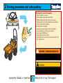
WARNING - CHANGING DIRECTION
STOP machine before changing direction - forward/
reverse or reverse/forward.
CAUTION
Novice operators should always begin with forward
motion on clear, level ground.
Driving procedure and safe parking
Moving from rest and stopping
• Select forward or reverse.
• Hold steering wheel with both hands.
• Slowly depress throttle pedal to move away.
• Remove foot from throttle pedal to slow and stop.
• Select neutral after stopping.
Park safely after operating:
• always leave skip empty in lowered position;
• ensure machine is on firm level ground;
• select neutral (FNR lever);
• stop engine and remove key;
• stow beacon for security (turn battery isolator off);
• lock engine cover.

3
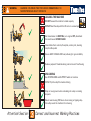
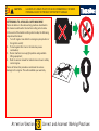
At t ent ion! Sect ion Correct and Incorrect Working Pract ices
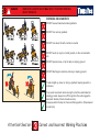
DANGER IMMEDIATE HAZARDS WHICH WILL RESULT IN SEVERE PERSONAL
INJURY OR DEATH
WORKING ON GRADIENTS
DO NOT exceed maximum stated gradients
DO NOT operate raise, or tip the skip on sloping ground
Travel straight up, down or along a gradient, keeping speed to a
minimum.
DO NOT turn across gradients
DO NOT run down hill with controls in neutral
DO NOT work on rough or rutted ground, or drive across kerbs
etc.
DO NOT discharge load when working on sloping ground.
To prevent movement when leaving the machine unattended on
sloping ground, always turn off the ignition (this will engage the
automatic brakes). Chock wheels securely .
Always position the skip in a forward-facing position. (Powerswivel
model only)

3
DANGER IMMEDIATE HAZARDS WHICH WILL RESULT IN SEVERE PERSONAL
INJURY OR DEATH
At t ent ion! Sect ion Correct and Incorrect Working Pract ices
VISIBILITY
Check ahead and behind machine before operation.
CRUSH ZONE
Stay clear of articulation area when the engine is running
WORKING UNDER A RAISED SKIP
Lock skip and lift arm with safety props during maintenance.
Be aware of low-visibility areas when operating.
Before operating, sound the horn to warn people in the
immediate area.
Never operate the machine’s controls when standing on either
side of machine
Never work under an unpropped skip or lift arm.

3
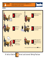
At t ent ion! Sect ion Correct and Incorrect Working Pract ices
WARNING HAZARDS OR UNSAFE PRACTICES WHICH COULD RESULT IN
SEVERE PERSONAL INJURY OR DEATH
LOADING THE MACHINE
DO NOT exceed the machine’s rated capacity
UNLOADING
Use STOPBOARDS and SUPPORT walls on trenches
DO NOT load the skip with the lift arms in a raised position
Set transmission to NEUTRAL, turn engine OFF, disembark
the machine and STAND CLEAR.
Clear debris from controls, floorplate, centre joint, steering
ram, throttle pedal
Ensure SAFE STABLE LOW load, allowing for good visibility
Reduce payload if materials being carried are not free flowing
DO NOT tip the skip if its load is sticking
Stop on level ground when unloading into a skip or raising
skip arm.
Select neutral using FNR lever when raising or tipping skip –
this will prevent the machine from moving

3
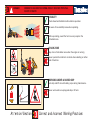
WARNING HAZARDS OR UNSAFE PRACTICES WHICH COULD RESULT IN
SEVERE PERSONAL INJURY OR DEATH
At t ent ion! Sect ion Correct and Incorrect Working Pract ices
DO NOT drive with the
skip in a raised or
tipped position
NEVER dismount from a
moving machine
Site hazards to avoid:
adverse weather
conditions; icy
surfaces; people
DO NOT carry
passengers
DO NOT operate with a
damaged ROPS frame or
when folded in the down
position
Avoid confined work areas -
exhaust fumes and noise
can be a hazard
Not e: damaged ROPS frame must be replaced
NOT NOT
NOT NOT
NOT repaired!
DRIVING

3
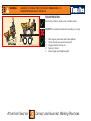
At t ent ion! Sect ion Correct and Incorrect Working Pract ices
WARNING HAZARDS OR UNSAFE PRACTICES WHICH COULD RESULT IN
SEVERE PERSONAL INJURY OR DEATH
TRANSPORTATION
Reverse the machine slowly onto a suitable trailer.
DO NOT the machine fowards when loading on a ramp
1 Stop engine (automatic park brake applied).
2 Chock wheels (to prevent movement)
3 Engage chassis locking pin
4 Secure to trailer
5 Ensure legal load (height/weight)
Page is loading ...
Page is loading ...
Page is loading ...
Page is loading ...
Page is loading ...
Page is loading ...
Page is loading ...
Page is loading ...
-
 1
1
-
 2
2
-
 3
3
-
 4
4
-
 5
5
-
 6
6
-
 7
7
-
 8
8
-
 9
9
-
 10
10
-
 11
11
-
 12
12
-
 13
13
-
 14
14
-
 15
15
-
 16
16
-
 17
17
-
 18
18
-
 19
19
-
 20
20
-
 21
21
-
 22
22
-
 23
23
-
 24
24
-
 25
25
-
 26
26
-
 27
27
-
 28
28


Thwaites Mach 202 Operator's Instruction Manual
- Type
- Operator's Instruction Manual
- This manual is also suitable for
Thwaites Mach 202 is a versatile machine designed for a wide range of construction site operations and transportation of bulk materials. Its capabilities include:
- Customary construction site operations
- Transporting bulk site materials
- Towing wheeled loads under controlled conditions
Ask a question and I''ll find the answer in the document
Finding information in a document is now easier with AI
Other documents
-
Terex TA10 Operators Instruction Book
-
-
Reliance 03-120 User manual
-
 John Deere 244J User manual
-
Wacker Neuson 3001 User manual
-
Poulan 157469 User manual
-
-
Weed Eater 157394 User manual
-
Vestil JMD-1000 Owner's manual
-
HUSTLER 4420 User manual
