McLaren MLX-1000 Owner's Manual And Installation Manual
- Type
- Owner's Manual And Installation Manual
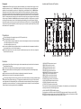
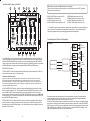
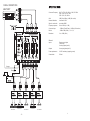
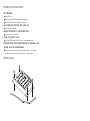
McLaren MLX-1000 is a 5-way electronic crossover network designed for multi-amplifier car audio systems. It features linear phase filters for natural sound reproduction, phase inversion switches for checking sound continuity, 180Hz mid cut controls, and 40Hz bass boost control for dynamic bass. With multiple input and output connectors, the MLX-1000 offers various system configuration options, allowing you to customize your car audio system for an immersive and high-fidelity listening experience.
McLaren MLX-1000 is a 5-way electronic crossover network designed for multi-amplifier car audio systems. It features linear phase filters for natural sound reproduction, phase inversion switches for checking sound continuity, 180Hz mid cut controls, and 40Hz bass boost control for dynamic bass. With multiple input and output connectors, the MLX-1000 offers various system configuration options, allowing you to customize your car audio system for an immersive and high-fidelity listening experience.


-
 1
1
-
 2
2
-
 3
3
-
 4
4
-
 5
5
-
 6
6


McLaren MLX-1000 Owner's Manual And Installation Manual
- Type
- Owner's Manual And Installation Manual
McLaren MLX-1000 is a 5-way electronic crossover network designed for multi-amplifier car audio systems. It features linear phase filters for natural sound reproduction, phase inversion switches for checking sound continuity, 180Hz mid cut controls, and 40Hz bass boost control for dynamic bass. With multiple input and output connectors, the MLX-1000 offers various system configuration options, allowing you to customize your car audio system for an immersive and high-fidelity listening experience.
Ask a question and I''ll find the answer in the document
Finding information in a document is now easier with AI
Other documents
-
zapco Z-II Series User manual
-
RBH Sound Signature SX-661/R Owner's manual
-
Cadence United Olympia User manual
-
-
-
zapco Z-SP Series User manual
-
 Pyramid Technologies CR-74G User manual
-
Power Acoustik C-30XR Owner's manual
-
Rockville Phenom RXA-T1 Owner's manual
-
