Page is loading ...

The Energy Guardian®
Pulldown Ladder Cover
Installation Instructions
For Support, Please Contact ESS Energy Products at: info@essnrg.com or 1-877-377-4674
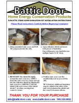
7. ADHESIVE
The Energy Guardian® Speed ADHESIVE is essential for
bonding components together. If ADHESIVE is included,
cut a small corner off the bottom of the pouch and apply
where needed. Apply in a thin bead or in a spot the size of a
nickel for maximum adhesion. Set time is approximately 20
minutes. Keep at room temperature prior to use (70°F is ide-
al). ADHESIVE may be also sold separately.
●
1. LID
Note: Your kit will have either a ONE PIECE LID or a TWO PIECE LID
3. SHORT FRAME SECTION
(x2)
5. HANDLE
(x3)
4. L-BRACKET (x2)
&
SCREWS (x4)
6. PIN (x6)
Cut small corner off
pouch to create this
COMPONENT LIST:
Please check that all components are included and not damaged by shipping. If you have missing or damaged
components, STOP and call Customer Service at 1-877-377-4674 before returning the kit.
2. LONG FRAME SECTIONS
Note: Your kit will have either ONE PIECE or TWO PIECE LONG FRAME SECTIONS

The Energy Guardian®
Pulldown Ladder Cover
Installation Instructions
Please check that all components are included and not damaged by shipping. If you have missing or
damaged components, STOP and call Customer Service at 1-877-377-4674 before returning the kit.
Glue Paern
ADHESIVE
ADHESIVE
TWO PIECE LID and LONG FRAME ASSEMBLY
NOTE: If your kit has a ONE PIECE LID, skip to HANDLE INSTALLATION section below
1. Lay two LID components and four LONG FRAME SECTIONS on a flat surface
2. Utilizing Glue Pattern apply ADHESIVE to inside of one LID half, where it meets with other LID half allowing lips to align
properly (See Picture #1)
3. Utilizing Glue Pattern, apply ADHESIVE to the end of a 30.5” LONG FRAME SECTION and join (See Picture #2)
so ends are flush with each other. This will create a 61” LONG FRAME SECTION. Repeat with remaining LONG FRAME
SECTIONS
4. Place LONG FRAME SECTIONS on outer sides of top of LID, using LID as a template to ensure LID and LONG FRAME
SECTIONS are flush (See Picture #3)
HANDLE INSTALLATION
1. Apply ADHESIVE to flanges of HANDLE (See Picture #4)
2. Apply two HANDLES to the lip of the LID, shoulder width apart. (See Picture #5)
3. Insert PIN through pre-drilled holes. Hold PIN by the stem and insert at least halfway into hole and foam to avoid
bending. Once inserted into foam, push from head of PIN until fully seated (See Picture #6)
4. Apply HANDLE to remaining SHORT FRAME SECTION (shown darker to emphasize HANDLE assembly) This is
the REMOVABLE FRAME SECTION (See Picture #7)
Picture #1 Picture #2
Picture #3
Picture #4
Picture #5
Picture #6
Picture #7
LID
LONG FRAME SECTION
LONG FRAME SECTION
LID
LIP of LID
Hold PIN by
stem to push
through the
hole and half
way into foam

Picture #9
5. To ensure that FRAME cures in proper alignment, place REMOVABLE SHORT FRAME SECTION (with HANDLE), at
open end of FRAME to complete rectangular shape of FRAME. DO NOT GLUE THIS SECTION! (See Picture #11)
6. Wrap tape around end to hold REMOVABLE SHORT FRAME SECTION in place while ADHESIVE cures (See Picture #12)
FRAME ASSEMBLY
1. Place LID down with lip of LID facing up. Label and HANDLES will be facing you (See Picture #8)
2. Using LID as template, place 2 LONG FRAME SECTIONS on the LID.
3. Utilizing Glue Pattern (see Picture #9), apply adhesive to both ends of the SHORT FRAME SECTION without the HANDLE
4. Using LID as template, place SHORT FRAME SECTION without the HANDLE between ends of LONG FRAME SECTION
to form “U” Shape for FRAME (See Picture #10)
APPLY ADHESIVE
TO BOTH ENDS
OF SHORT
FRAME SECTION
LID
LONG FRAME SECTION
LONG FRAME SECTION
LID
TAPE
REMOVABLE
SHORT FRAME
SECTION
FRAME INSTALLATION After 3 hours, the frame should be ready for installation.
1. Apply Adhesive to end of both LONG FRAME SECTIONS only at end where REMOVABLE SHORT FRAME SECTION is
located (See Picture #13 and #13a ). Utilize Glue Pattern.
2. Remove FRAME from LID and carefully flip FRAME over so ADHESIVE is facing the floor/deck of attic (See Picture #14).
3. Carefully place FRAME around attic opening so ADHESIVE makes contact with the attic floor and the REMOVABLE
SHORT FRAME SECTION (taped end) is located at top of ladder where you step into the attic (See Picture #15).
4. For Trussed Roof Construction (PT1 and PT2 Kits), Install FRAME in between roof trusses (Shown on next page)
5. NOTE: If gaps are present between bottom of FRAME and attic decking, this is addressed in FINISHING INSTALLATION
ADHESIVE
FLIP FRAME SO
ADHESIVE IS
UNDERNEATH
Picture #13a
Picture #14
Picture #8 Picture #10
SHORT FRAME
SECTION
Picture #11 Picture #12
Picture #13
Picture #15
FLIP FRAME
LID
LID
LID
LID
ADHESIVE

L-BRACKET ASSEMBLY
1. To ensure a snug fit of REMOVABLE SHORT FRAME SECTION, install L-BRACKET on outer side of both LONG
FRAME SECTIONS even with REMOVABLE SHORT FRAME SECTION (See Picture #16)
2. Using SCREWS, secure L-BRACKET to floor of attic so vertical side of L-BRACKET is snug against the LONG
FRAME SECTION (See Picture #17)
3. REMOVABLE SHORT FRAME SECTION should now fit snugly between the LONG FRAME SECTIONS
REMOVABLE
SECTION
L-BRACKET
L-BRACKET
FINISHING INSTALLATION
1. Once the L-Brackets are installed, remove the tape holding the REMOVABLE SHORT FRAME SECTION in place
2. If gaps exist between bottom of FRAME and attic decking, apply a generous bead of expanding (one-part) foam or caulk
around the base of the FRAME, filling in gaps. DO NOT APPLY FOAM OR CAULK TO REMOVABLE SIDE (See
Pictures #18 & 19)
3. When installing the LID, the label and handles should face towards pulldown ladder, not towards attic
4. Use shims to level the FRAME if necessary due to very uneven attic flooring or decking (Foam will handle most gaps)
5. Use caution when removing the LID to enter attic. Make sure it is off to the side and secure so it stays put until you
replace it on your way down the attic stairs
6. Make sure the LID is seated properly - Make sure lip of LID is seated inside frame to maintain the proper air seal
7. Always use caution when entering or exiting your attic
8. If you encounter a situation installing your Energy Guardian Pulldown Ladder Cover where you need assistance, please
call us between 9:00-4:00 EST at 877-377-4674
LONG
FRAME
SECTION
ATTIC
FLOOR
Picture #16
Picture #17
If gaps exist between kit and uneven
ac deck:
If gaps exist between the ac decking
and the wooden ac opening frame, ll
all gaps with Expanding Foam or caulk
See Picture #20
DO NOT FOAM REMOVABLE SECTION!
Use Expanding Foam to ll gaps
around the outside of Frame.
DO NOT FOAM REMOVABLE SECTION
GAP
GAP
Picture #18
Picture #19
Picture #20
REMOVABLE
SECTION
/